
Greetings the inhabitants of our site!
As you know, LED lighting devices are quite economical, relatively inexpensive and, in theory, have a very long life. But in practice, everything is slightly different.
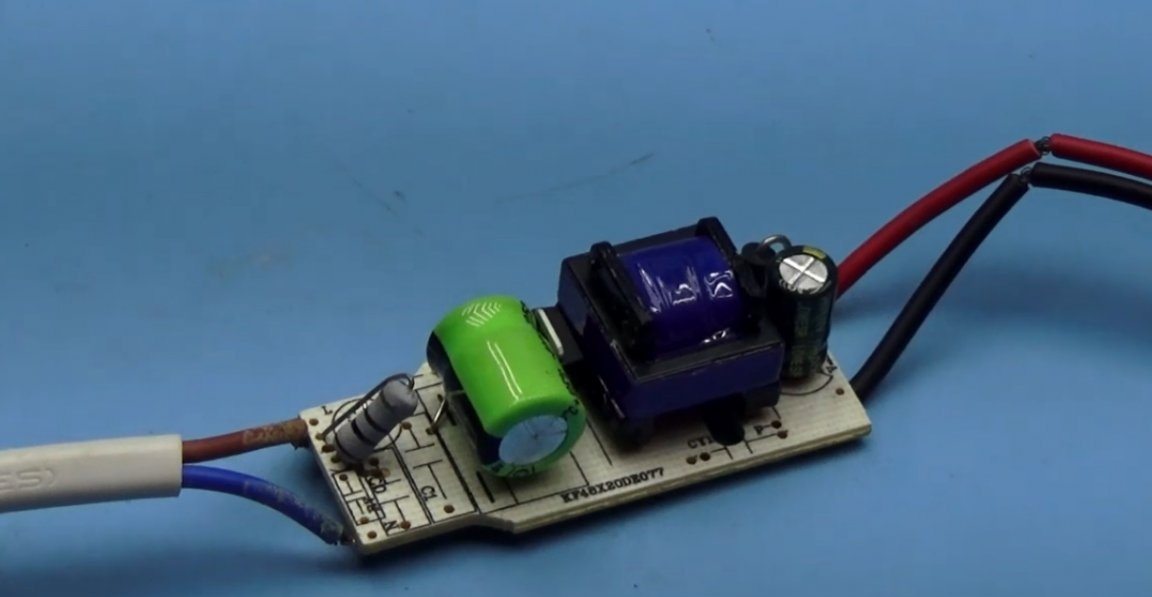
Due to the low-quality power sources that are available in any LED lamp, such lamps have a relatively short life. Both power sources and the LEDs themselves fail. In some cases, repair is impractical, since it will be much cheaper to buy a ready-made lamp. But sometimes a malfunction can be associated with the failure of just one or more LEDs. If the lamp is built on the basis of the matrix, then this will not work to be repaired - only a replacement.

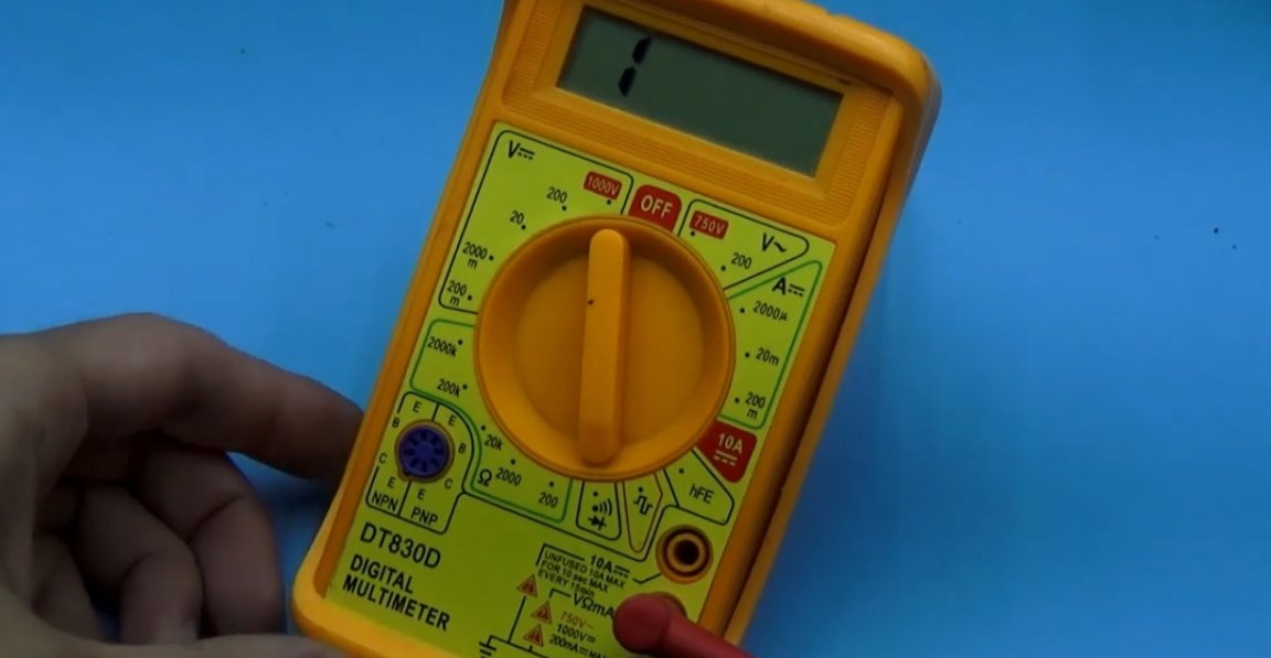
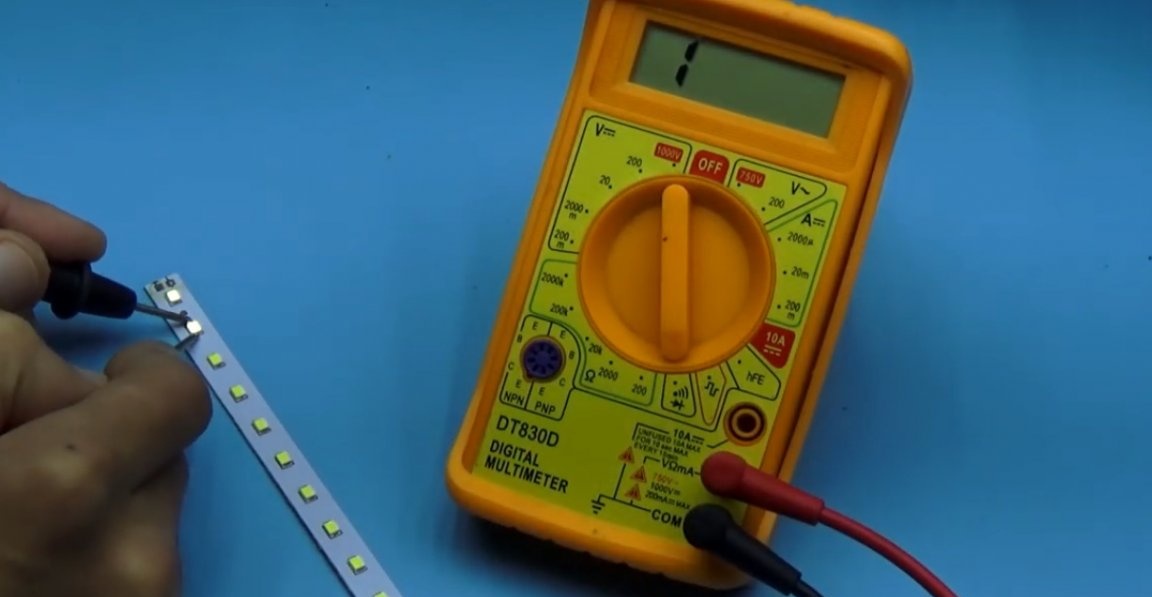
In other cases, you can always find and replace a faulty LED. LEDs can be checked for serviceability using some multimeters or a power source, after limiting the current with a resistor.
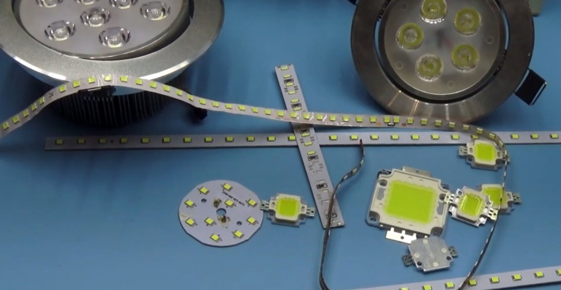
Modern LED luminaires use a series of LEDs connected in series-parallel and checking each LED individually takes a lot of time.
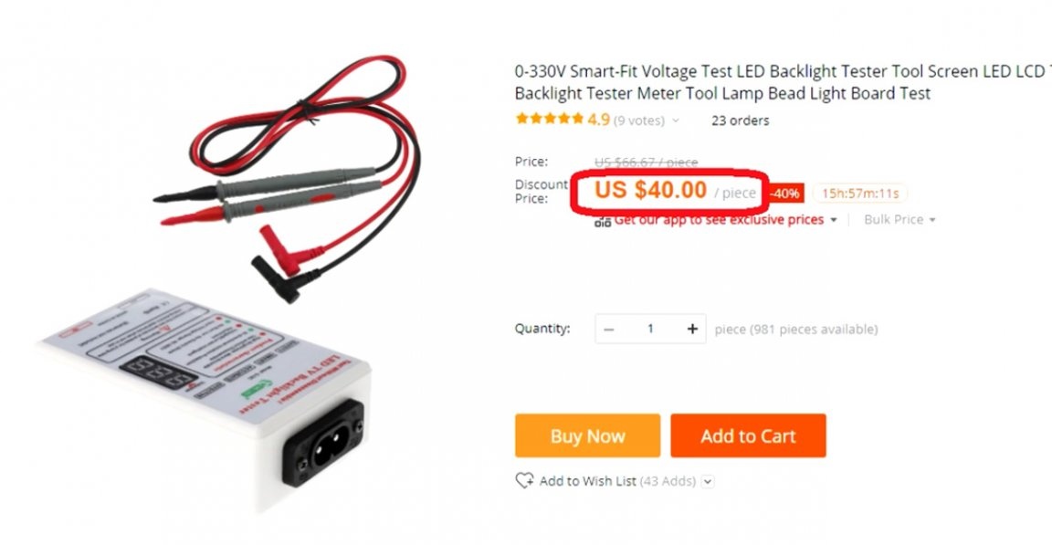
Our Chinese friends have long been selling appliances specifically for this purpose.
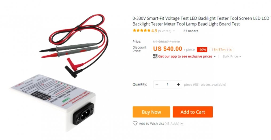
Such devices provide high output voltage and low current, which will allow you to find a faulty LED in the lineup in a couple of seconds. But such devices are by no means cheap, so the author (AKA KASYAN) decided to create his own version of a similar device. Moreover, this option will also be portable.
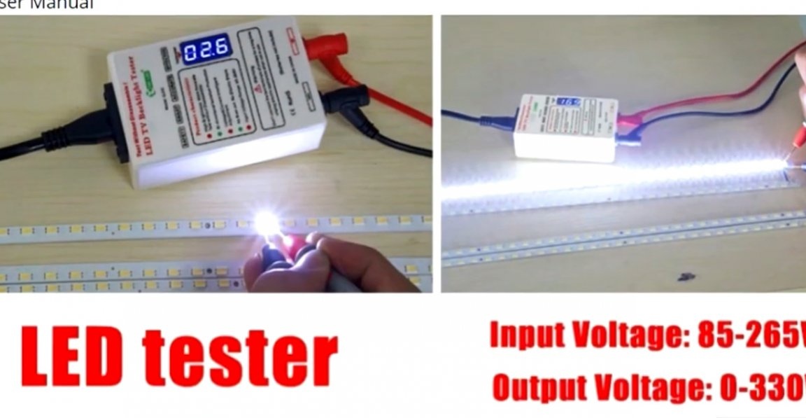
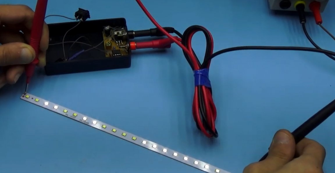
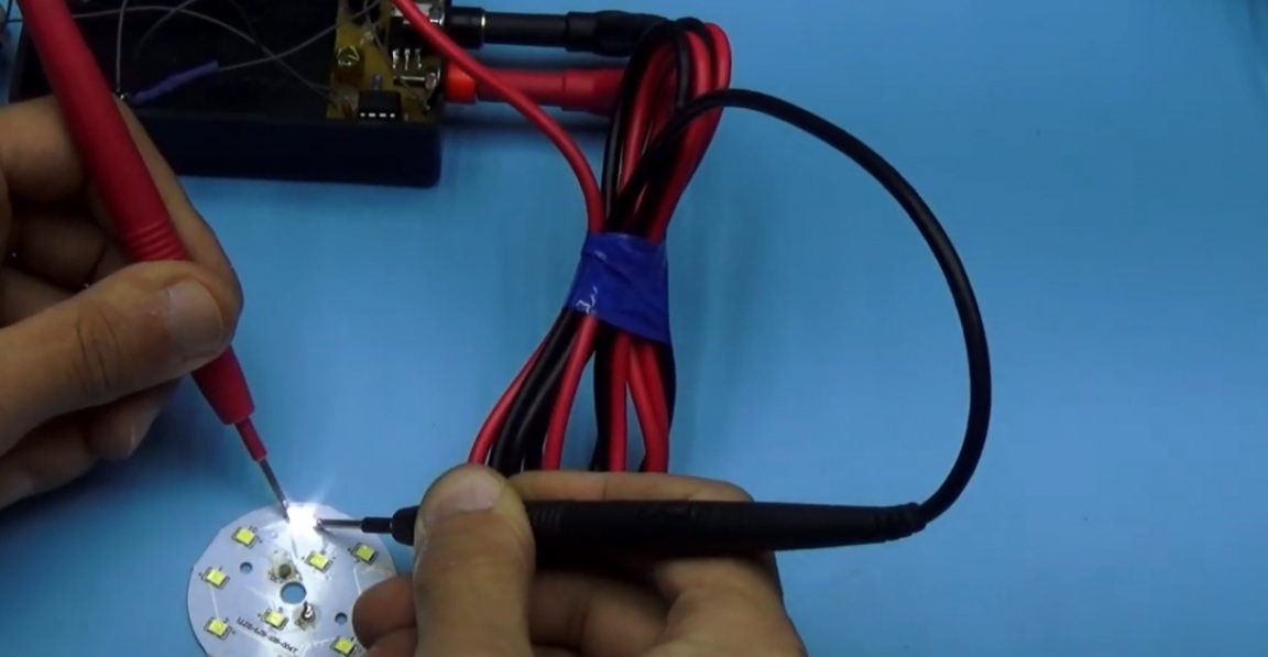
Such a thing will be useful for repairmen, since it can be used to repair LED backlights of monitors, as well as LED strips and rulers with any number of LEDs connected in series.
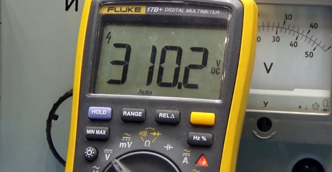
The presented device provides a constant voltage of about 320V and an insignificant current at the output. The device is in no way connected to the network and is completely safe, even if you touch the high-voltage contacts during operation.
Such a device will allow you to check a circuit of more than 100 series-connected LEDs, that is, it is enough for any lamp.
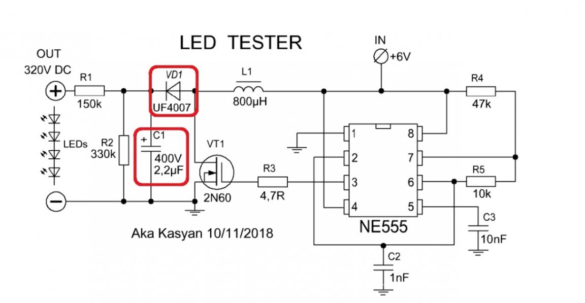
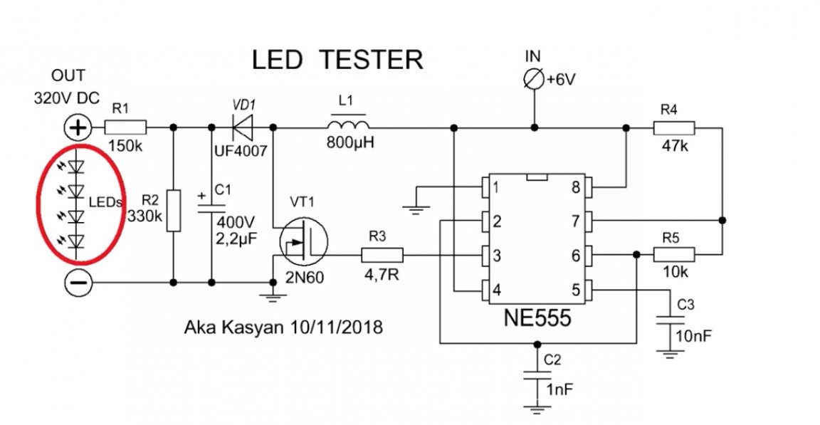
How does it work. Let's look at the device diagram.
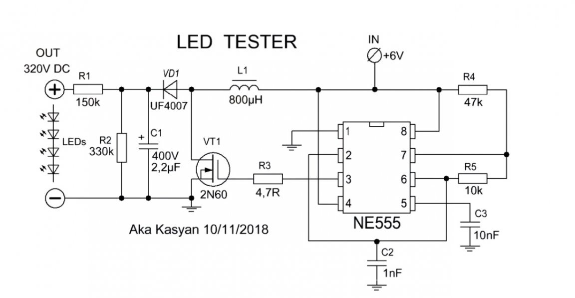
On the basis of the NE555 timer, a rectangular pulse generator is assembled. The frequency of the generator is about 20 kHz.
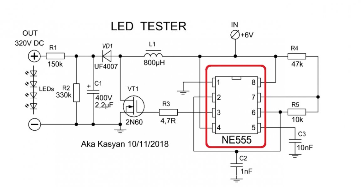
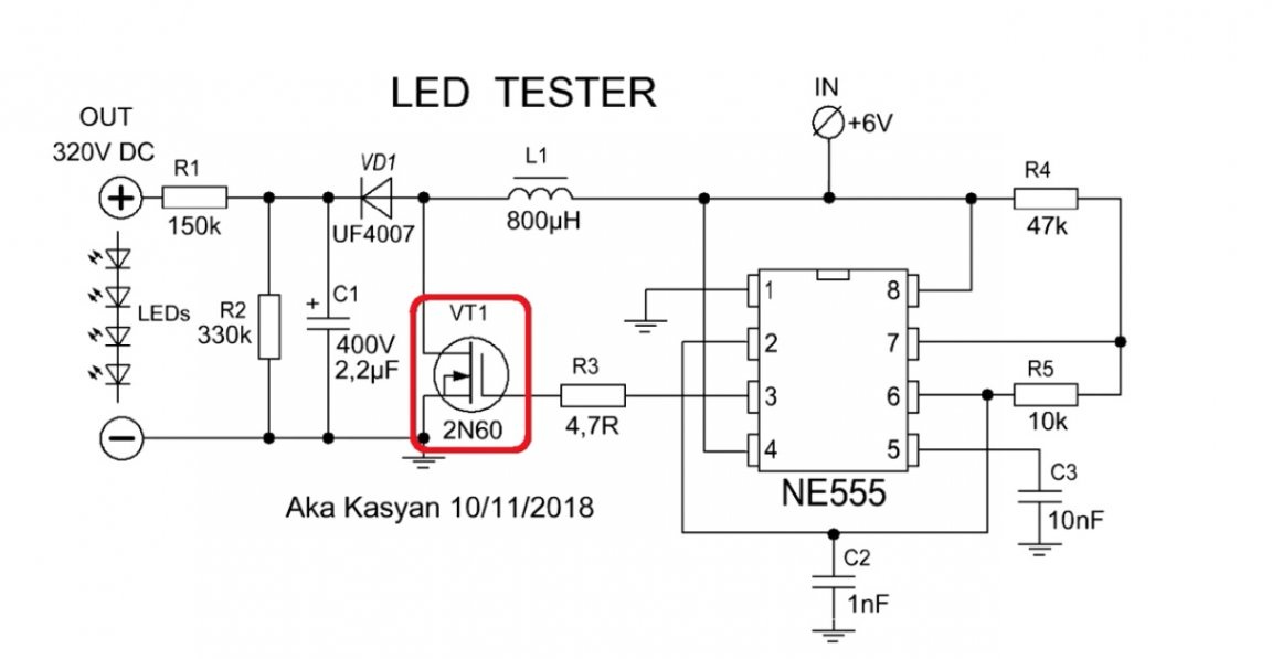
The signal from the timer output goes to the gate of the high-voltage field-effect transistor. The latter, opening, closes the inductor to the power source. At this stage, energy is pumped into the throttle.
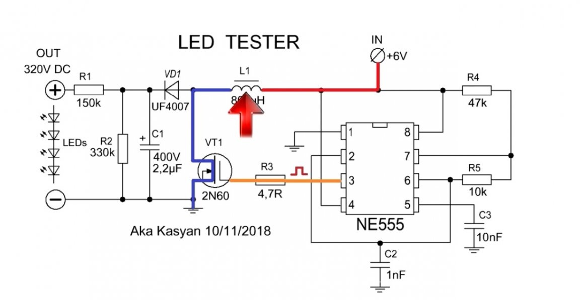
Next, the transistor closes, the inductor gives up the previously accumulated energy in the form of a voltage surge, which is ten times more than the supply voltage.
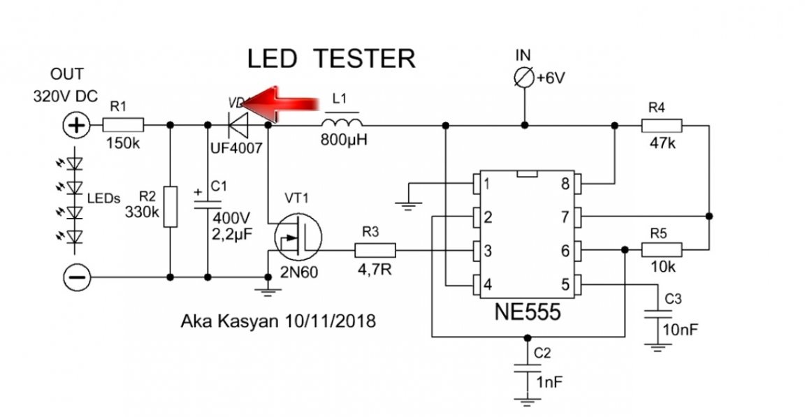
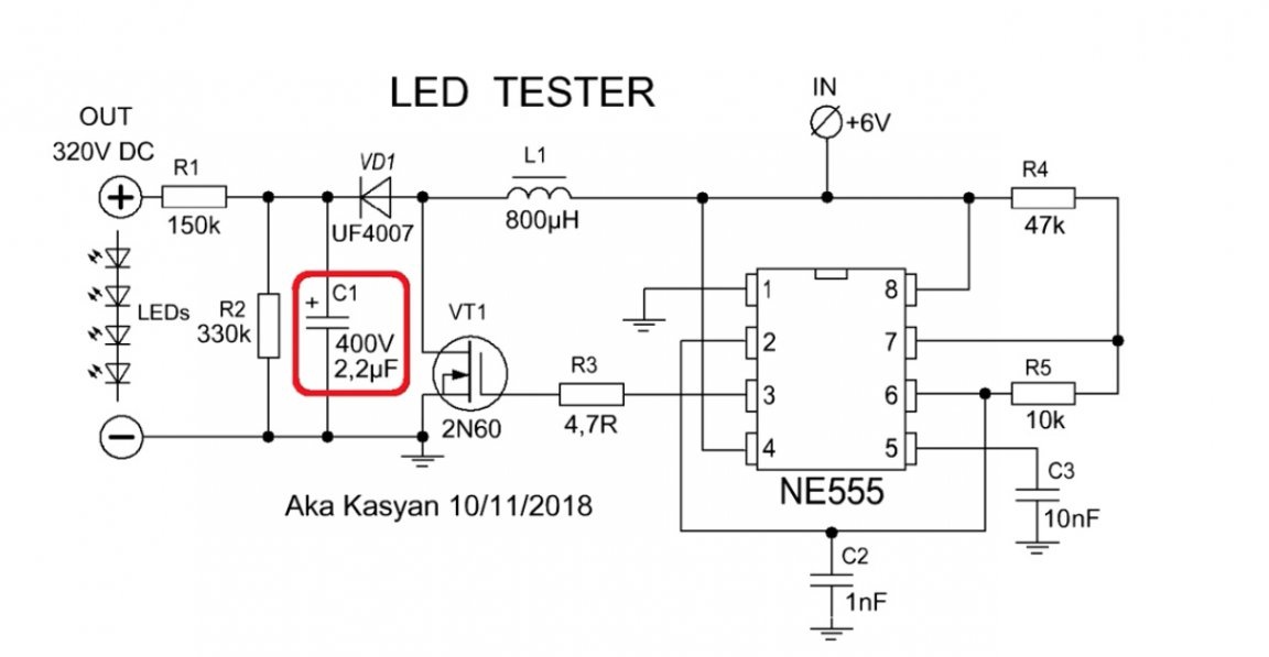
This voltage is rectified to a constant and accumulates in a high voltage electrolytic capacitor.
Our dc-dc converter is a normal booster without feedback. That is, the output voltage is not stabilized and depends on the power source and load power. The device is assembled on a simple printed circuit board and it can be together with a common archive. Also, the links are in the description under the video (link SOURCE).
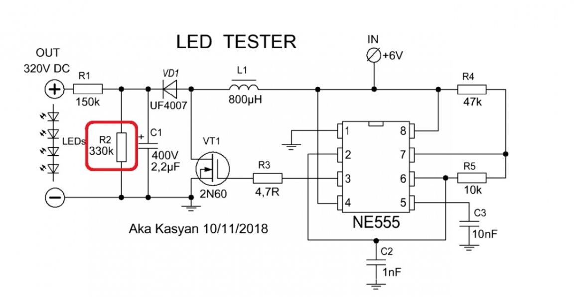
At idle, the voltage across the capacitor will increase, which will lead to a breakdown of the latter. Therefore, a load resistor was added to the circuit. The same resistor discharges the capacitor after turning off the power.
The circuit has another 1 resistor, it is current-limiting.
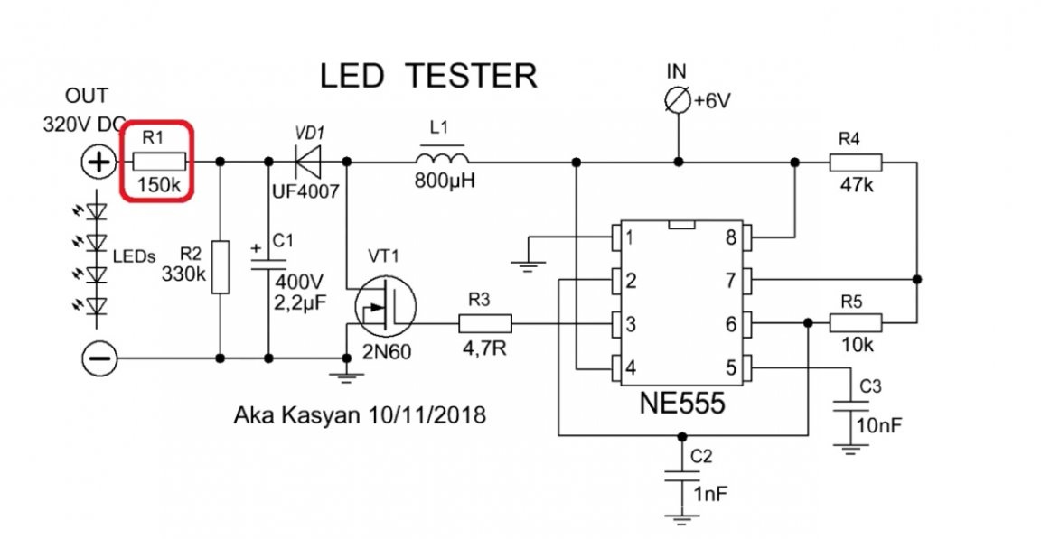
If you connect the LED under test without this resistor, then the voltage from the capacitor instantly enters the diode by burning off its crystal. The resistor is selected so as to limit the current to 5 mA, this value is safe for any LEDs.
When connecting an LED or a line of LEDs, the output voltage from the converter decreases to the value that the LEDs need and is equal to the sum of the voltage drop across all the LEDs. Roughly speaking, the load and at the same time the stabilizing link are the LEDs themselves.
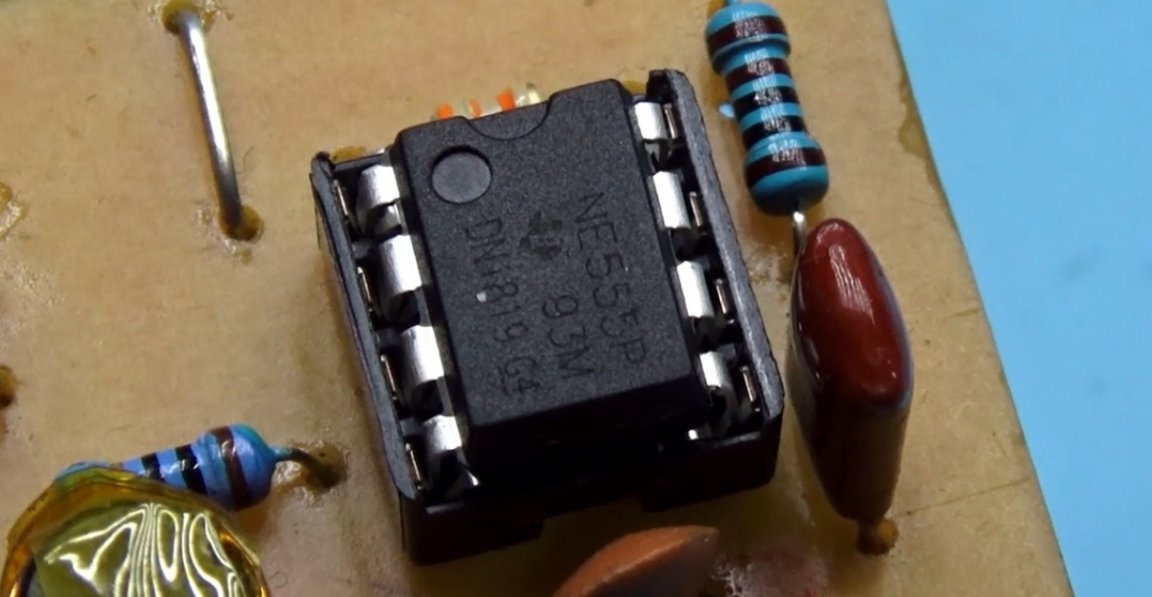
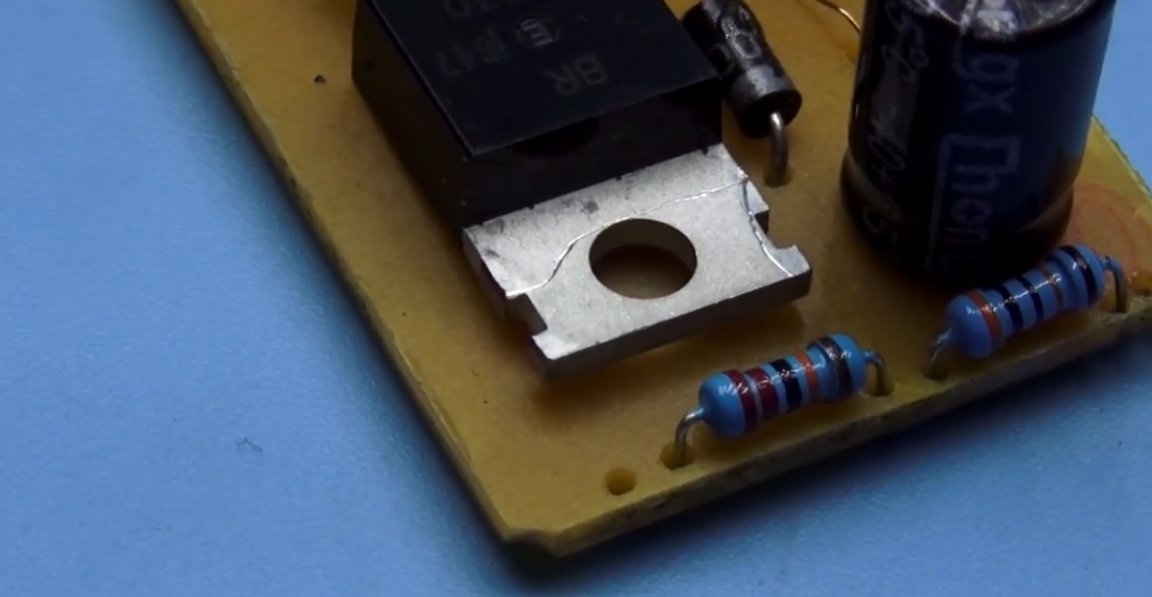
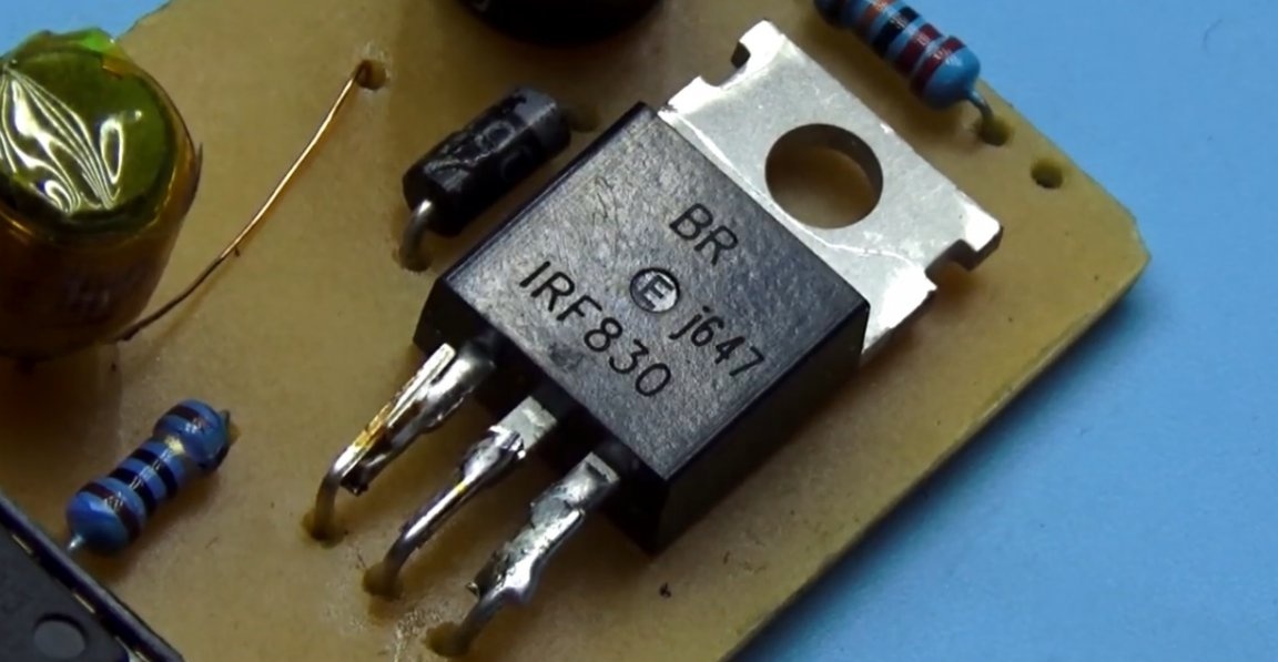
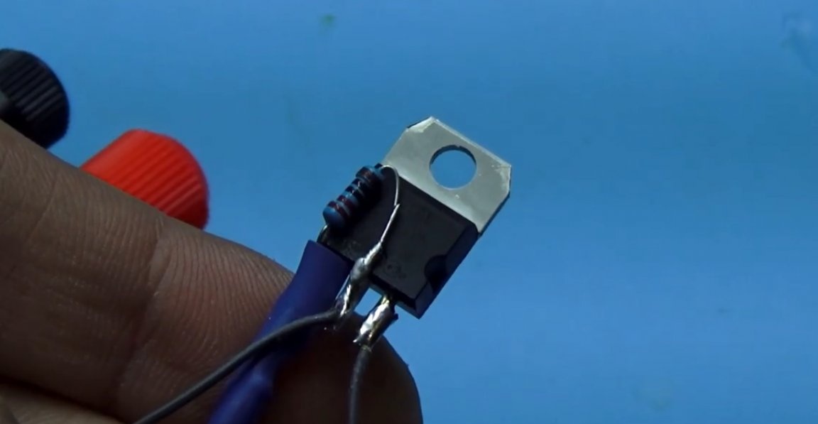
Circuit components. Well, there should be no problems with the 555 timer and its binding, everything is standard here. The field effect transistor needs a high voltage n-channel. The author used IRF830. but advises transistors like 2N60 and 4N60, they have more voltage margin, and the current for our circuit is not so important.
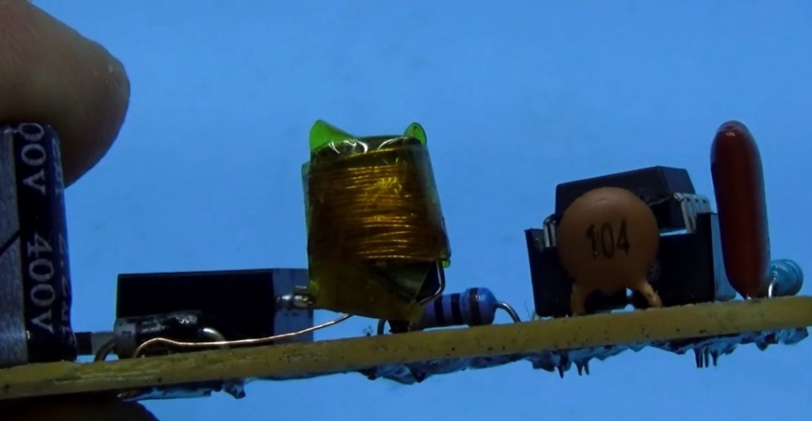
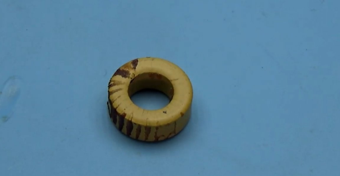
The inductor is wound on a ferrite dumbbell, the wire is 0.15, the inductor inductance is from 800 to 1000 μH. Can be wound on iron powder rings or on a ferrite rod.
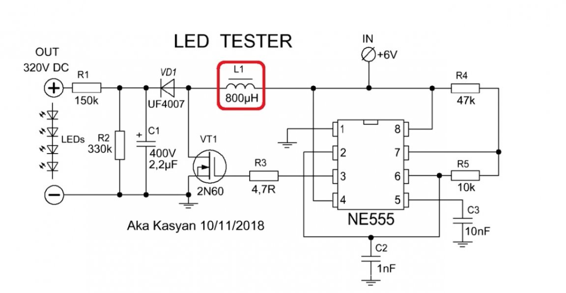
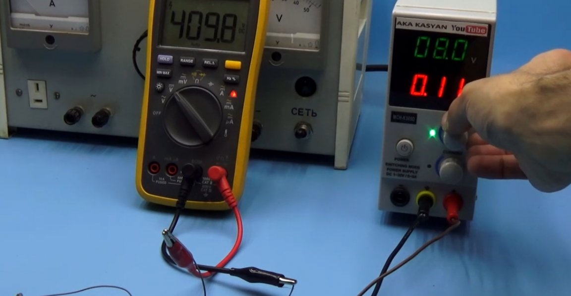
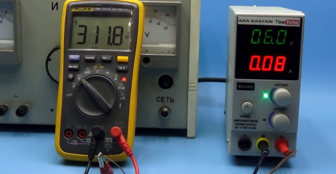
As already mentioned, the output voltage of the converter depends on the input. With a supply voltage of 6V, the output is about 320V, but with a voltage of 8V input, the output is more than 400V.
The voltage also depends on the inductance of the inductor. The greater the inductance, the greater the voltage. The author also added a 6V linear stabilizer to the circuit. Thus, the output voltage will be kept more or less stable, regardless of the discharge of the battery.
The stabilizer in this case is built on the basis of lm317, but it is also possible on the chip 7806. The idle current of the converter is 80 mA, but at the output we have a load resistor. Without it, the converter will consume less.
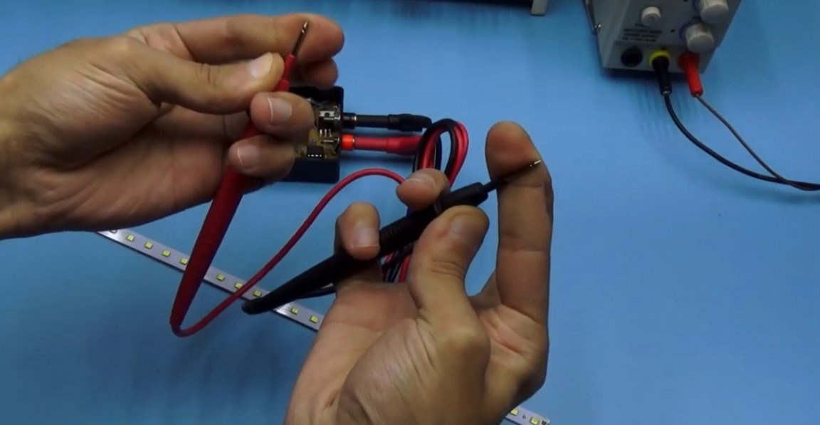
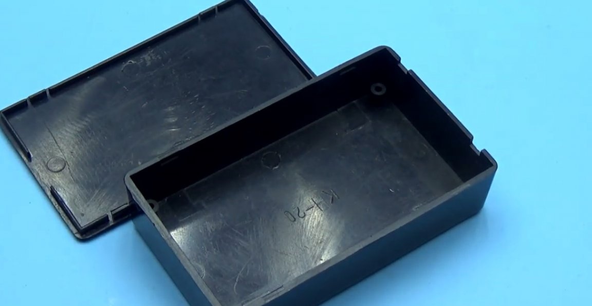
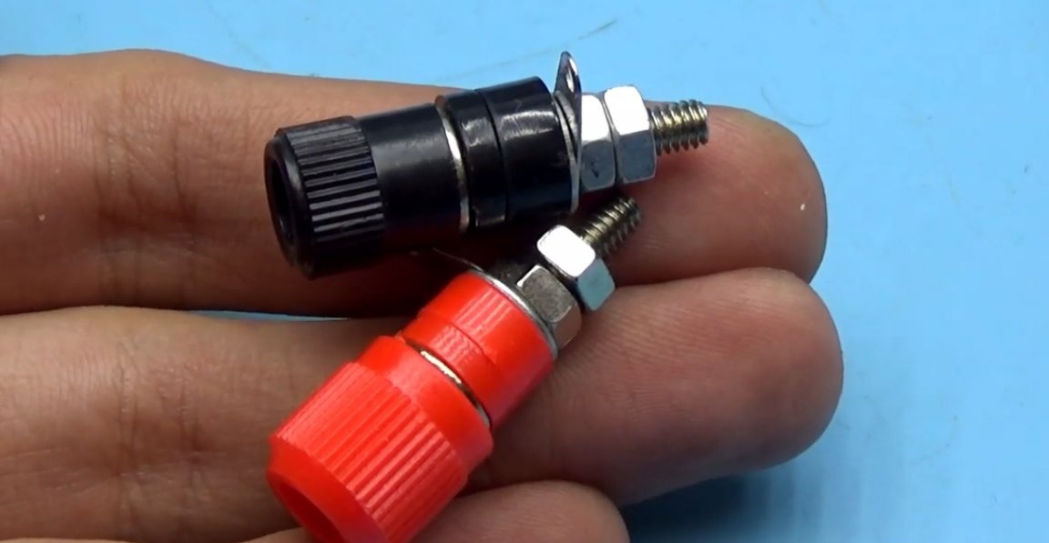
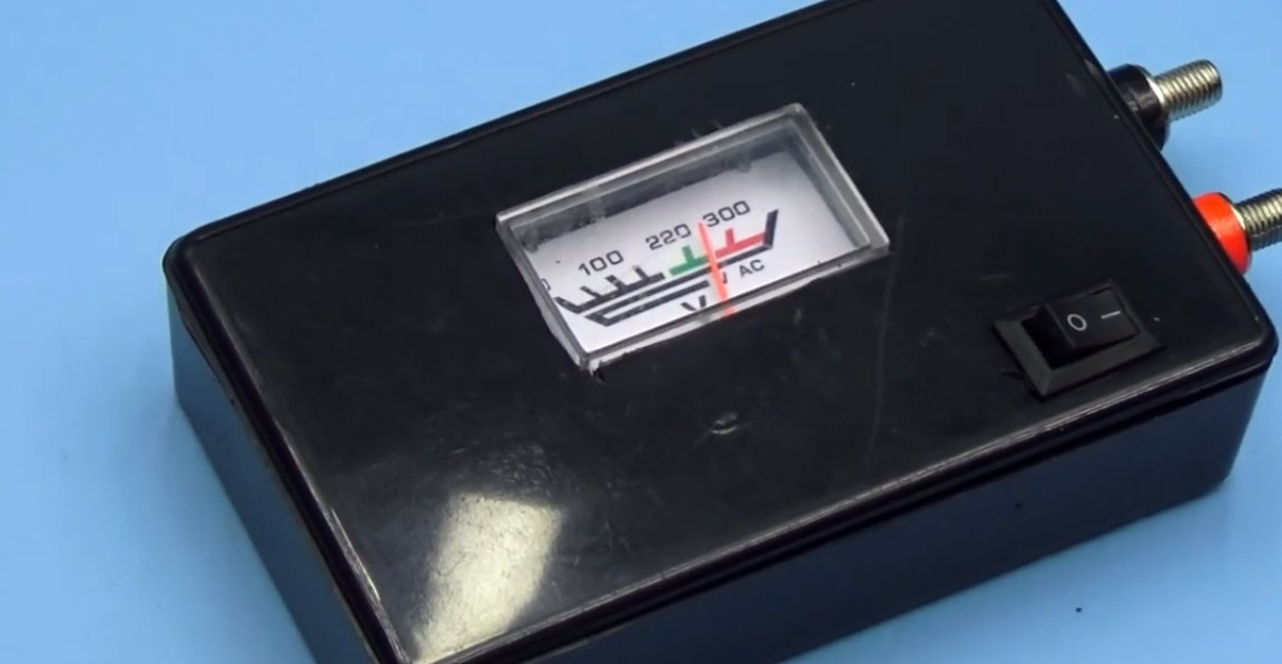
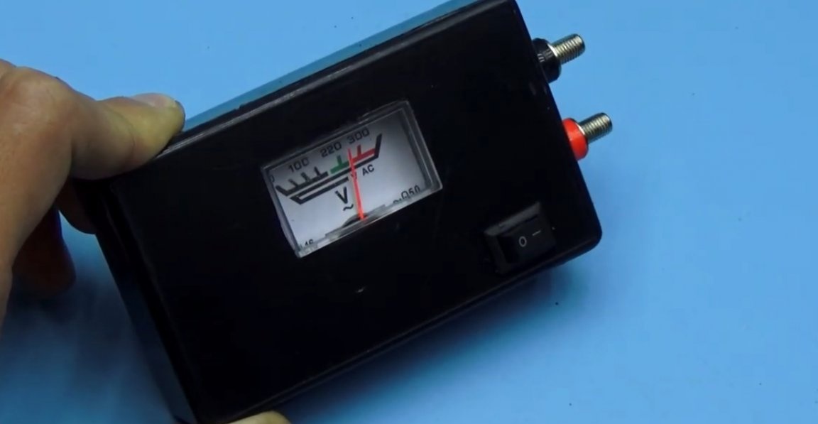
With all this in mind, from a conventional 9V battery, the converter can work continuously for 2-3 hours, from alkaline batteries much more. So even with the active use of the device, the batteries will last for a very long time. The finished device fits in any suitable enclosure. For convenience, the author put a couple of terminals.
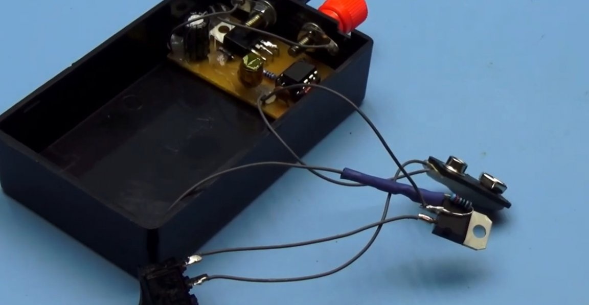
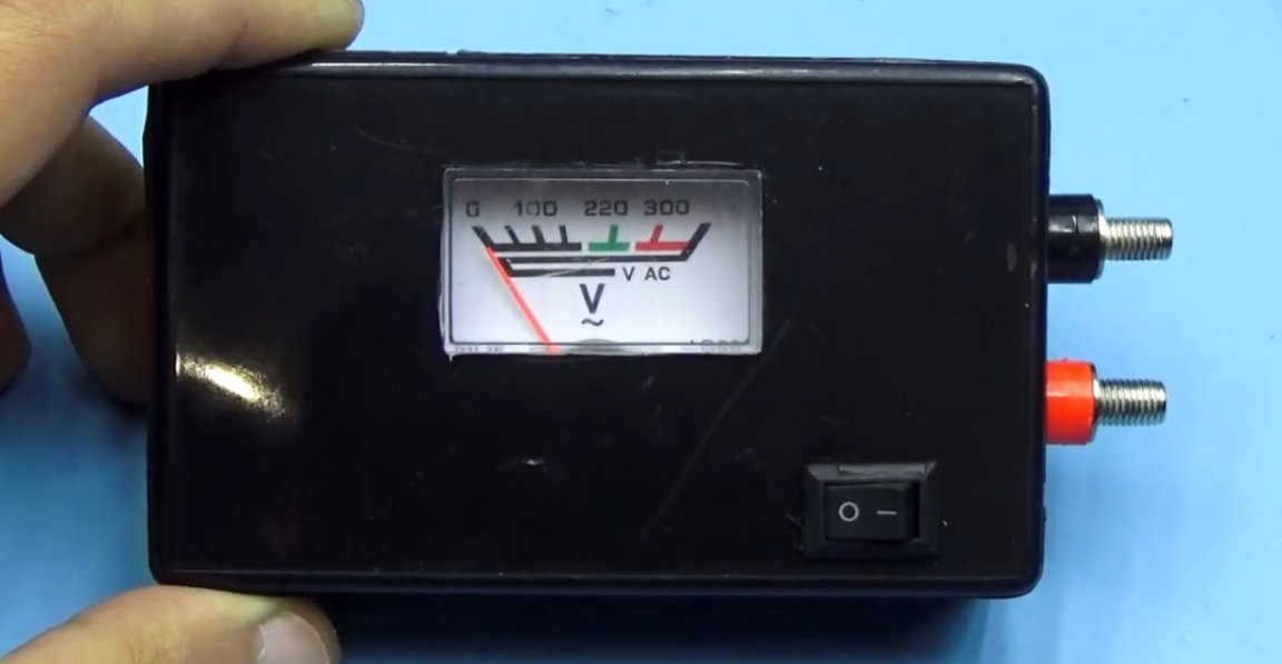
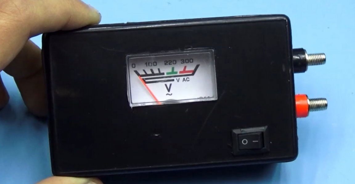
An analog voltmeter is connected to the output of the converter, which was torn from the voltage regulator.
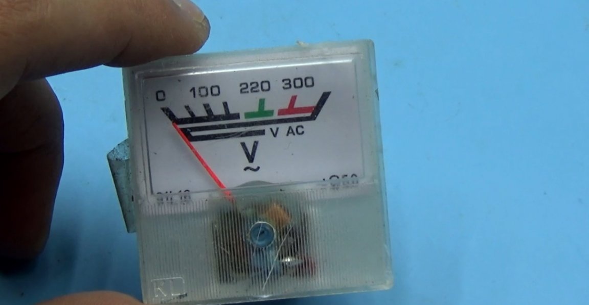
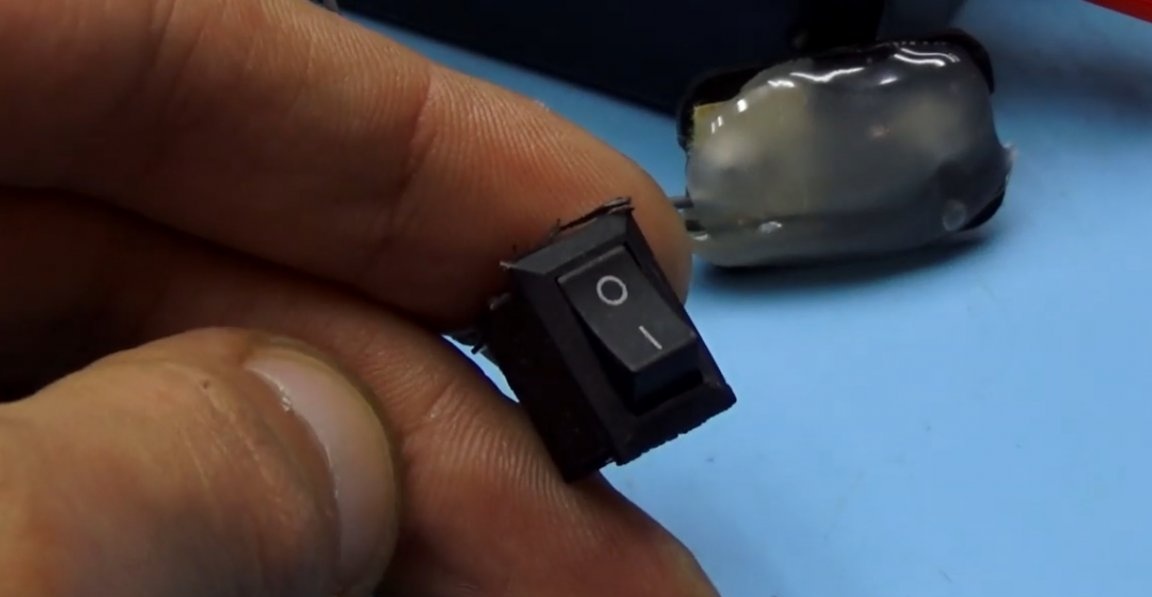
This type of voltmeter has 1 rectifier diode, and for good it needs to be replaced with a jumper. But here, especially accurate readings are useless, and the voltmeter itself is not super accurate. Using it, you can visually understand what voltage drop on the line of LEDs. A switch was also added, well, that’s all.
As a result, we get a ready-made device that will definitely help out in the repair of LED lamps. Thank you for attention. See you soon!
Video: