

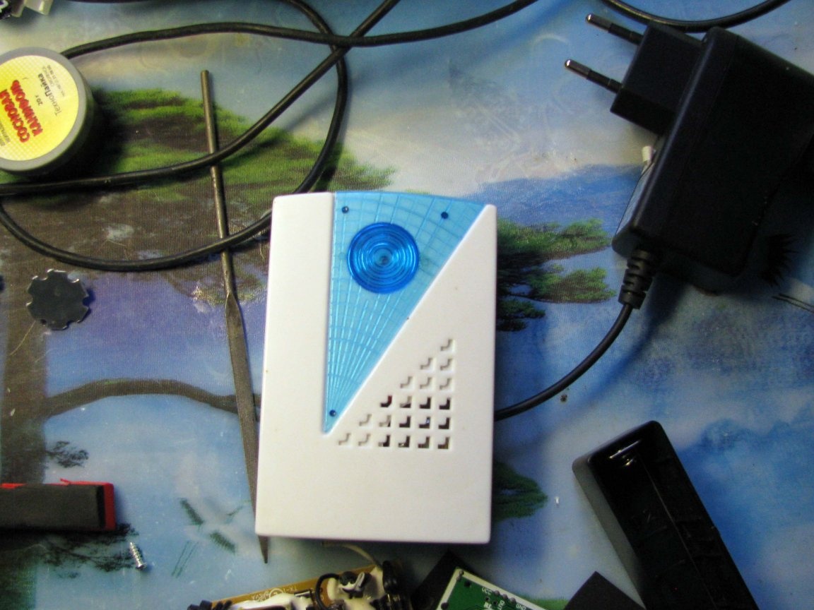
Some of the owners of private and non-private homes use wireless calls. They are available in two versions: powered by the mains, and powered by batteries.
For three years, I changed two models, the last - this one, on battery power.
I fed it through an external +3 volt power supply, which, in fact, produced about five without load, so as not to risk electronics, I fed the circuit from the AMS1117-2.8v integrated stabilizer.
The bell has a single button with which you can change the melody. The first thing that is set by default after power is one of the loudest, there is another one, a little different and the same loud. But, as soon as the power disappears - the selection is reset to the melody by default.
In general, I’m tired of constantly pushing the button, and the bell always plays the first melody - this is the first inconvenience of this device, however, except for battery power before.
The second inconvenience stems from the first - when the house is dead, the bell does not work, although the remote button has its own power source and is fully operational.
The third, in my opinion, is that something else is missing - the outlet under the ceiling is occupied by a single device. And I must say, a small corridor in front of the front door is always dim. Day or summer, this does not play any significant role, since the doors do not close for a long time and in addition, you can always turn on the overhead lighting. But at night (go out to smoke), to the nearest switch you need to go a few steps in complete darkness, - it is not impressive to look for matches, a pack and galoshes by touch.
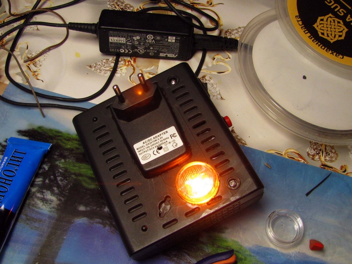
I suggest that you take a look with me what happens if you cross the call, uninterrupted power, motion sensor and LED.
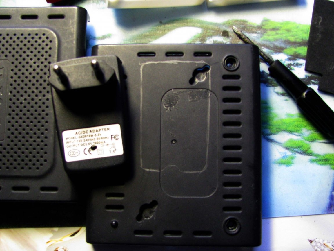
I have left:
- housing from a small ADSL modem that could go to the manufacture TV set-top boxes;
- +5 volt power supply removed from the housing my previous homemade;
- a small radiator;
- yellow LEDs from of this project;
- a single-cell bank that has been idle for the third year.
I also had an orphaned case plug from an unknown power supply in the box, and with a little brain, I decided to try to cross it with the ADSL modem case.
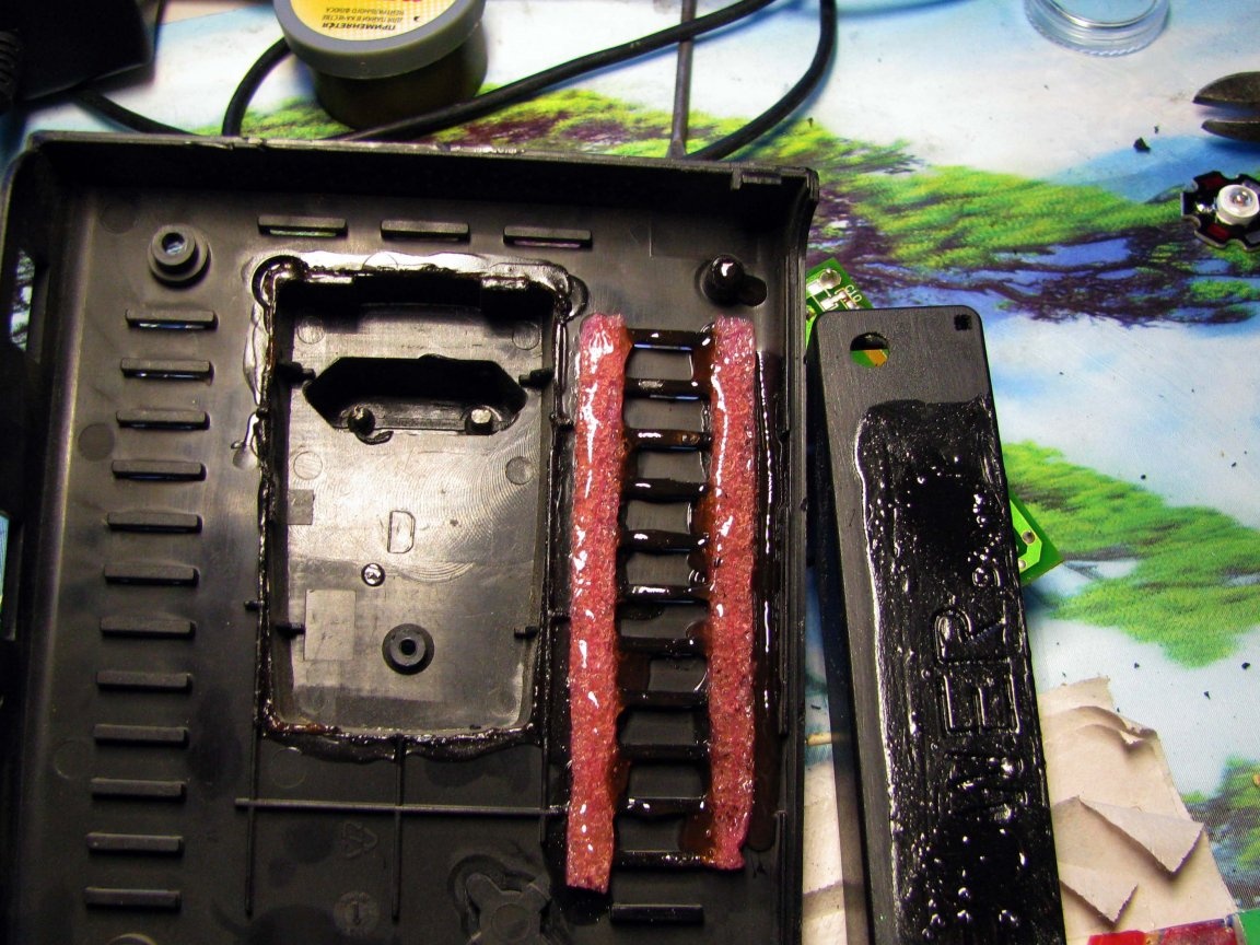
The edges of the sawn window were moistened with glue many times, so that the edges of the window softened slightly.In addition, I was lucky - the tide of the ADSL modem case required a hole in the power bank case - this will be another power point of attachment.
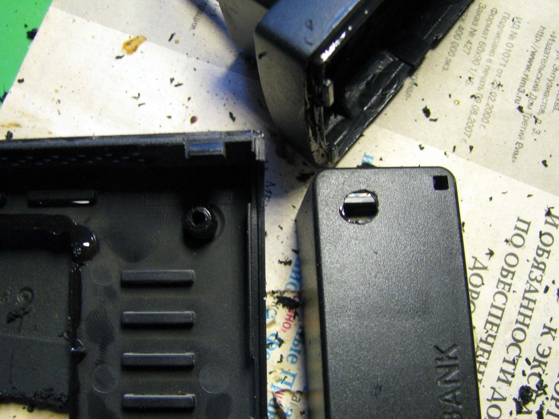
Additional strips of foamed polyethylene will increase the contact surface between the two housings. Also, note that the pocket for soldering 220 volt conductors in the chassis plug - quite deep - is another piece of luck.
The first fitting and estimation is “what else do I really want?” - I had to invent on the fly, in my head there was only a vague idea of the final result.
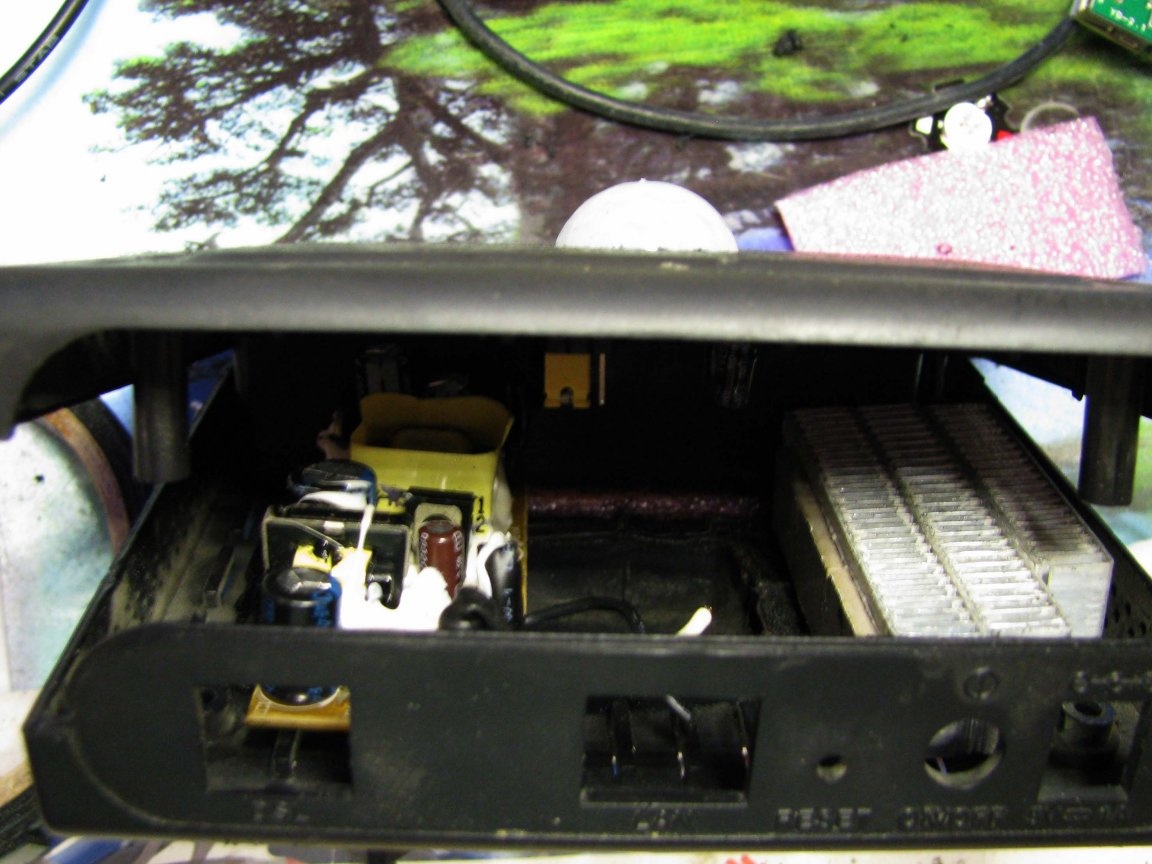
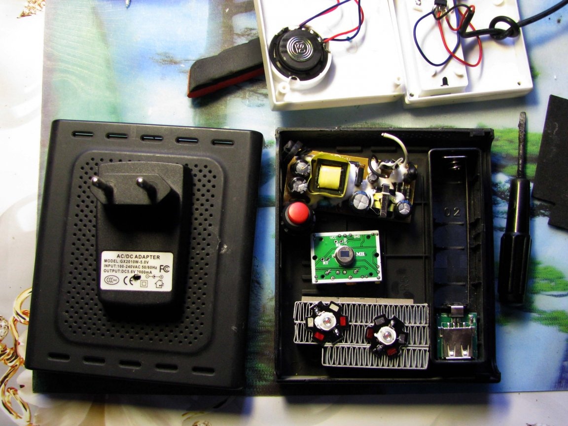
Half of the bank lost its regular filling, to me, the weekend is +5 extra. Instead of the standard scheme, the usual TP4056 charge controller is used, the same as I used in this homemade.
The power supply network wires were soldered to the contact pins, and the board itself was glued to a suitable place in the ADSL modem through a piece of foamed polyethylene. And thus, a roomy basement was formed.
The power switch is placed in the gap of the wires going to the future load. Those. the load can be disconnected from the battery protection board. The battery itself will be constantly connected to the charge circuit.
I planned a button for outputting contacts for changing melodies.
And the through hole is for installing the LED.
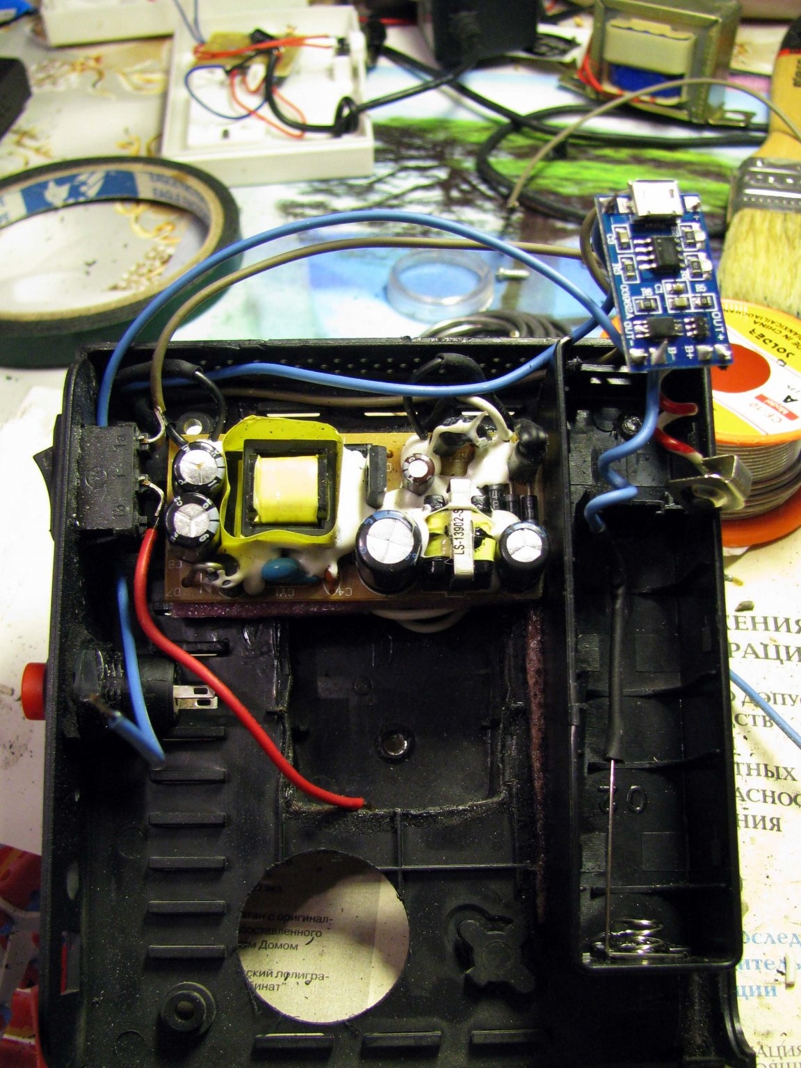
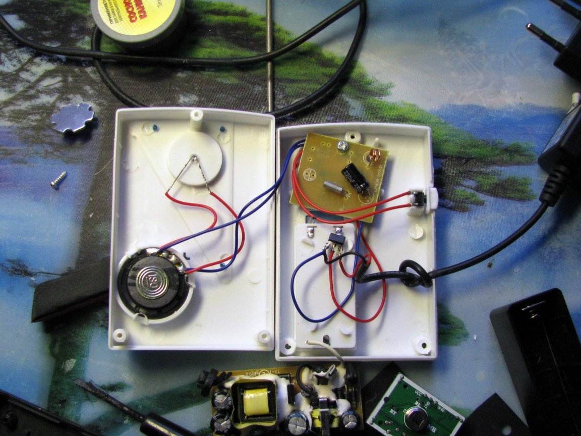
I was lucky again (as I wrote above), there was a rather capacious basement of the hull plug and the call card successfully fit into it, which was immediately done. The 18650 battery from the battery of the old laptop was placed in a makeshift battery compartment, the wires to the button for changing the ringtones were soldered, the power of +2.8 volts remained the same, the miniature sound emitter was conveniently placed under the button for changing the melody and the imperfection was put in place - it was late and had to sleep.
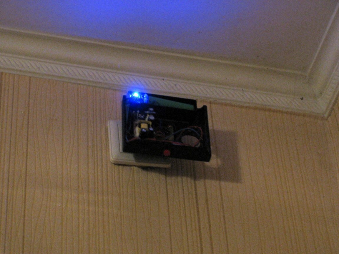
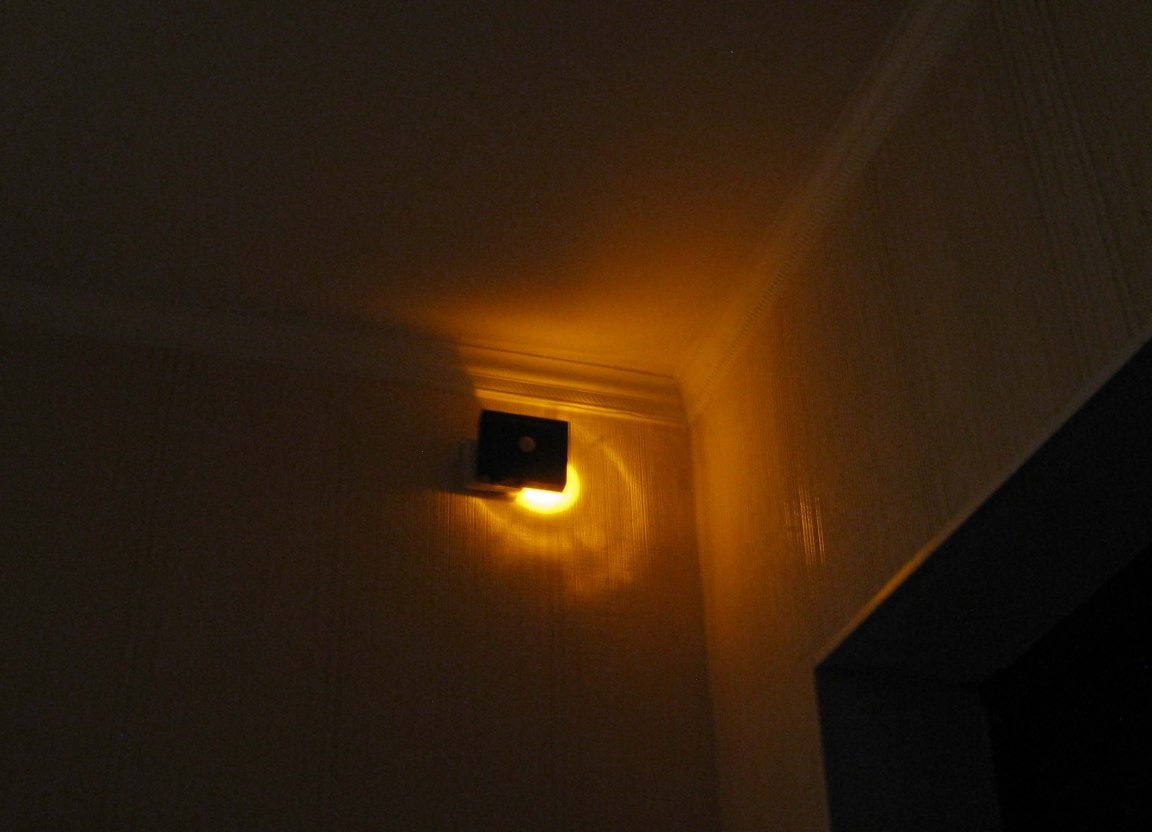
Looking at the super-bright blue LED that flooded the small corner of the hallway, I doubted what I was doing - it seems that I am complicating things again.
Lighting.
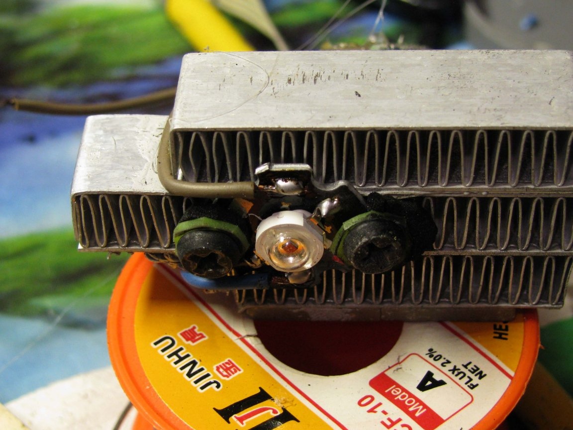
Through the gaskets, I screwed the star with the yellow, three-watt LED soldered on it and brought the wiring to the back of the radiator.
As a driver for the LED, I decided to use the AMC7135 current stabilizer
The integrated driver is, in fact, a managed field key.
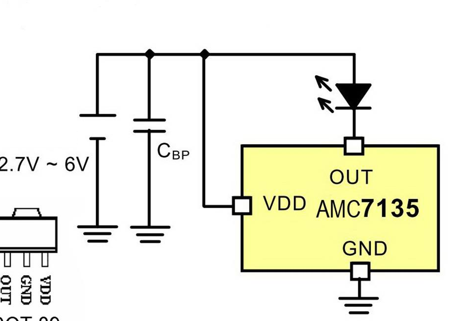
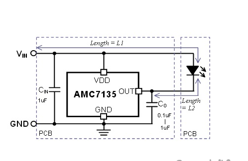
Blocking capacitors are used with a significant length of connecting wires.
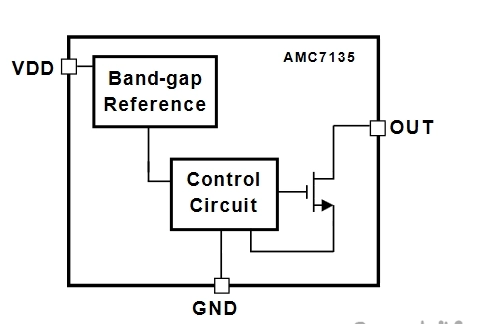
However, if you look closely at the structural diagram of this stabilizer, it becomes clear that it can be controlled. Namely, the Vdd pin through which very little power is supplied to the stabilizer itself can be switched. Excellent.
The PIR SR501 sensor is also very famous.
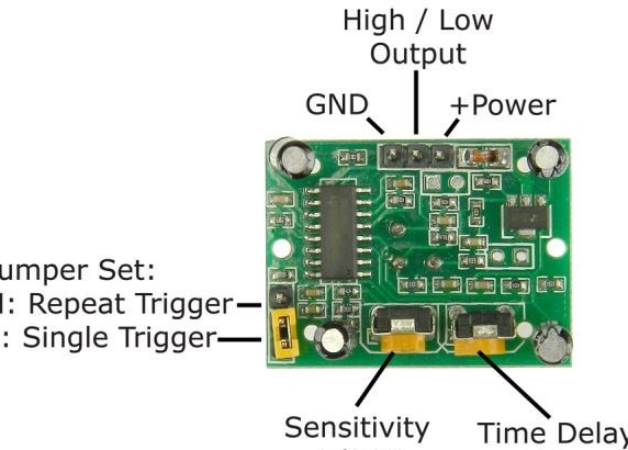
I’ll only pay attention to the jumper H-L.
L - one-time operation of the sensor for the first detection of a motion event - holding the set time, regardless of whether there was repeated motion detection during the set holding time - a pause of several seconds - readiness for the next cycle.
H - one-time operation of the sensor for the first detection of a motion event - endurance of the set time, and in the case of detection of repeated motion - a constant reset of the endurance timer.
I installed naturally H.
The time has come to see how my conclusions are true.
+4 volts from an external power supply were applied to the motion sensor and to the AMC7135 block, and the OUTPUT pin of the detector was connected to the Vdd of two combined current drivers.
Since each driver produces a current of 350mA, and a three-watt LED consumes 600mA, I decided to use two drivers connected in parallel. But, due to non-optimal installation, and despite the blocking capacitors, the circuit was excited. Therefore, I limited myself to a single driver.
When I already connected both the bell, sensor and LED unit to a single power source, I found that when playing a melody - the LED picks up a beat - its brightness changes along with the sounds emitted.
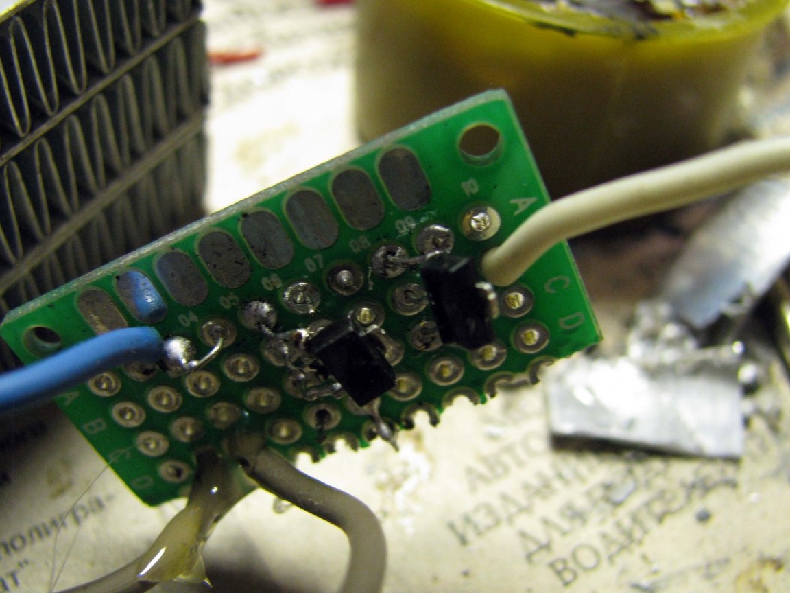
I had to get a small circuit board, and on it to unsolder the power points distributed from a single power source. A capacitor of 1000 microfarads solved the problem of blinking with an LED.
Pieces of polyurethane foam were fixed by a radiator with an LED, and the remaining empty windows in the ADSL modem case were covered by a heat-shrink tube in which the AMC7135 shawl was located.
The LED was covered with a glued transparent cover.
The final fitting showed that there was enough light for emergency lighting.
Eventually:

What could be done differently and the advantages of homemade:
- The radiator was clearly superfluous. When feeding a three-watt LED with half current, it does not heat up at all. even if homework danced all day with bears, gypsies and balalaikas before the resulting homemade;
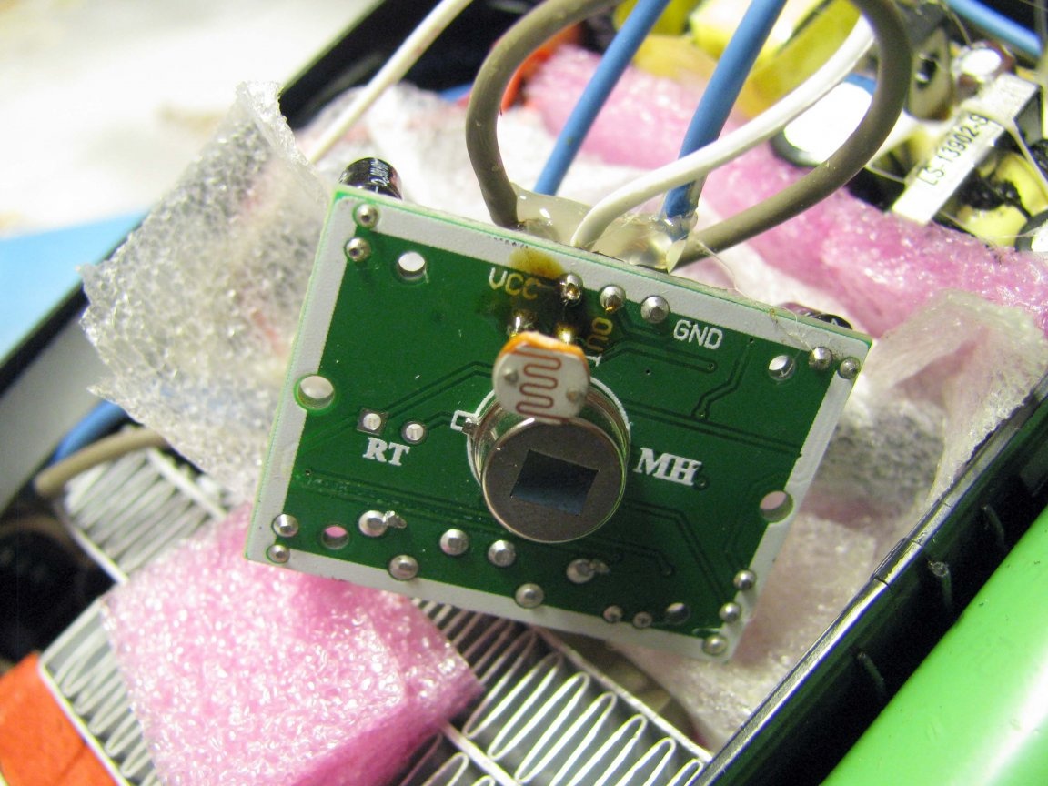
- on the PIR detector board there is a mounting place under the photoresistor, which would not allow the LED to operate under ambient light conditions. But, I suspect that I will not wait for these photoresistors this year - the package seems to have been lost;
- the LED itself, one could choose another. Yellow, even at rated current - 600mA is not very bright. This is evident from the results of my previous homemade. The greenest LED turned out to be the brightest at the same current, but, I only have yellow ones;
- the established melody will no longer be reset when power supply 220 volts disappears;
- during the day the LED is on, it’s not very visible, the lithium 18650 is constantly connected to the charging circuit, and the yellow color does not annoy the light at all - so let them dance.
PS. If I’m lucky and don’t have to resend the photoresistors again, then I will update the homemade product and add photos to the article.
References:
- current driver;
- integral stabilizer;
- ;
- .
UPD
Good luck. Photoresistors did come. But, as I did not guess when ordering, one resistor was not enough - the backlight did not turn on even in complete darkness.
As can be seen from the figure below, the photoresistor forms a divider in series with R3 and in a good way, to fine-tune the photosensitivity it would be necessary to put a tuning resistor, but I do not want a long-term construction.
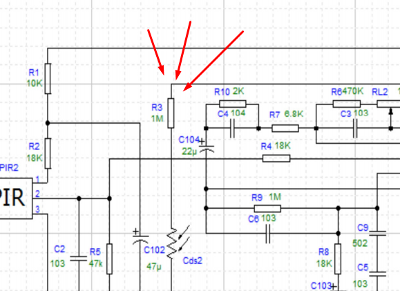
Therefore, I decided to try two series-connected photoresistors, and here, success awaited me. The sensor stopped responding when the upper light was on.
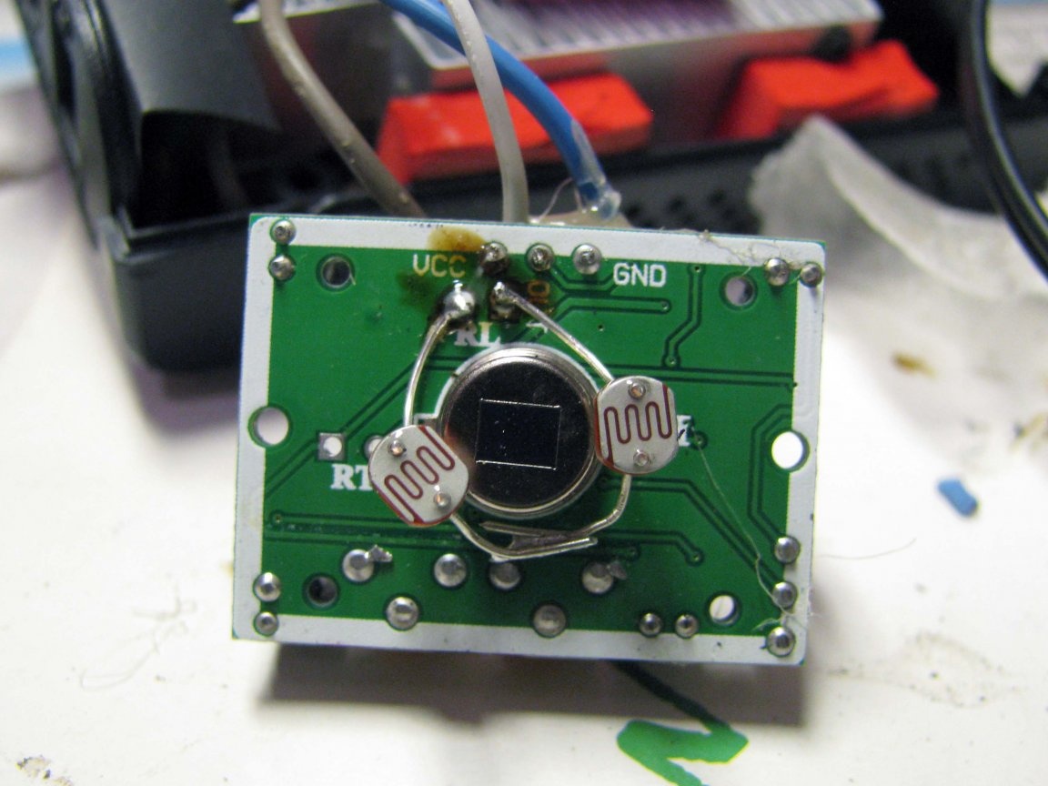
From the link below, I bought resistors with the parameters "5506". Direct light of a desk lamp - 54 Ohms, if closed with a finger - 15 kOhms, if closed with the center of the palm - 60 kOhms.
- datasheet;
- .
And so I implemented an anti-vandal button:
The battery, if that changes at times, this is the second, the first lasted a year and a half.

Now - EVERYTHING =)