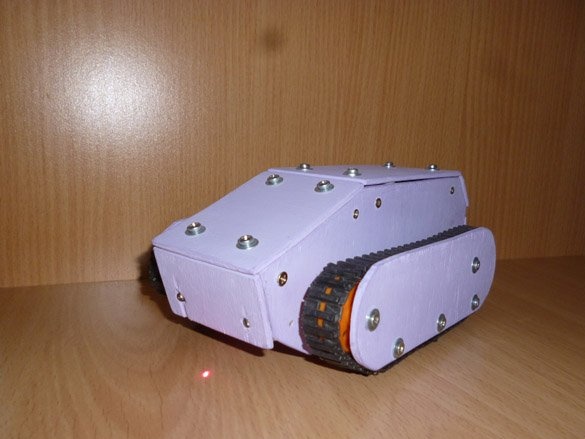
Good afternoon, we continue to make robots and toys. Today, the next step is the modification of my tank model. Readable Manufacturing Instructions here
The essence of the modification is to change the way of management. This time, for control we will use a laser pointer. More precisely, the tank will ride behind the laser dot. The tank will determine the location of the point through photoresistors. The list of necessary is similar to the list from the above homemadebut not quite:
- Tamiya 70168 dual gear
- Tamiya 70100 set of rollers and tracks
- Tamiya 70157
- Plywood 10 mm (a small piece)
- Arduino Pro Mini 5V AtMega 328
- DRV 8833
- Photoresistors 5506 4 pcs.
- USB-UART for Arduino firmware
- Rectangular red and green LEDs
- White LEDs 5 mm 2pcs.
- Resistors 3x 150 Ohms
- Li-ion 18650 batteries
- Dupont Dad-Mom Connectors
- Wires of different colors
- solder
- Rosin
- soldering iron
- Bolts 3x40, 3x20, nuts and washers for them
- 2x10 wood screws
- Wood drills 3 mm and 6 mm
- Electric fret saw
- Acrylic paint
Step 1 Production of tank parts.
Detailed tank manufacturing process described in homemade.
Repeating it makes no sense. Therefore, the first and second step of the above homemade complete.
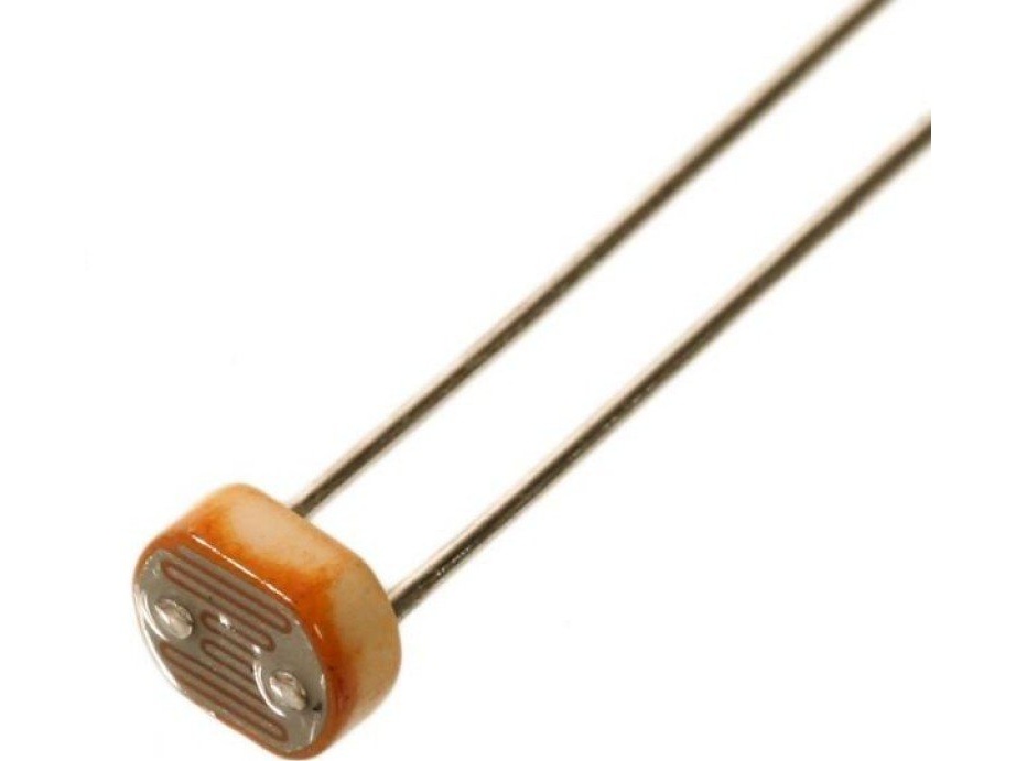
Step 2 Installation of photoresistors.
We will need the most common photoresistors, they are easy to buy at the radio store:
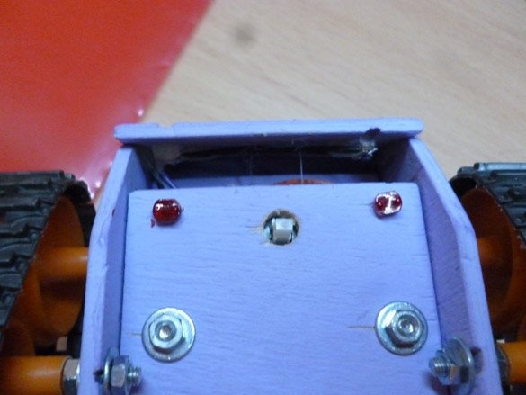
Next, before installing the tracks, you need to prepare places for the photoresistors and insert them there. So, we have four photoresistors, two in the front, two in the back. They will all be located in the lower part of the case, in the corners. Retreating 5 mm from each side, make two holes for the legs of the photoresistor. The distance between the holes is 4 mm. You can use a drill of the smallest diameter or just pierce the veneer with an awl. Having done this, insert the photoresistors. Let's start with the front:
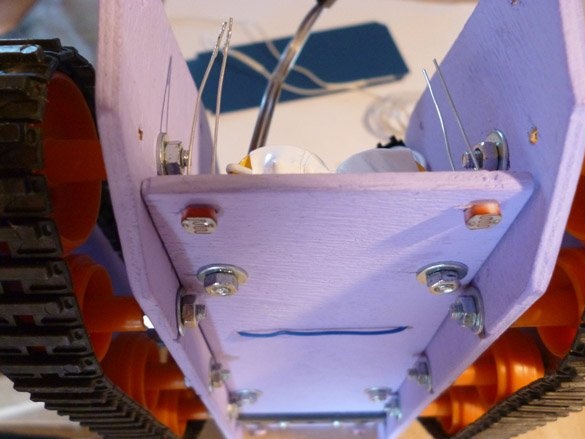
After you inserted the photoresistors into the plywood, solder the wires to the contacts and the Dupont connector of the mother. We isolate the place of soldering. You can use electrical tape, or you can, like me, put insulation on the wire thicker.
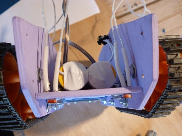
And in the back we also do:
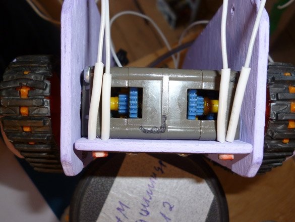
Below will look like this:
We assemble the case further according to the instructions, the link to which is indicated above.
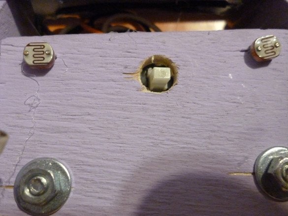
To increase the sensitivity of the photoresistors to the laser point and get rid of unnecessary interference, they must be painted with a red marker or paint. The main thing is that light penetrates through the coating. Do not completely paint over them.
In this way, we will increase the sensitivity of the sensors to the red dot of the laser.
Step 3 Electrician.
In the fourth step, instructions for making the tank describe in detail what and how to connect. We do everything according to it, with the exception of connecting the Bluetooth module. We do not need him. We connect one of the contacts of the photoresistors to GND. The second is connected to Arduino according to the scheme:
Front right to A0 (Pin14)
Front Left to A1 (Pin15)
Rear Left to A2 (Pin16)
Rear Right to A3 (Pin17)
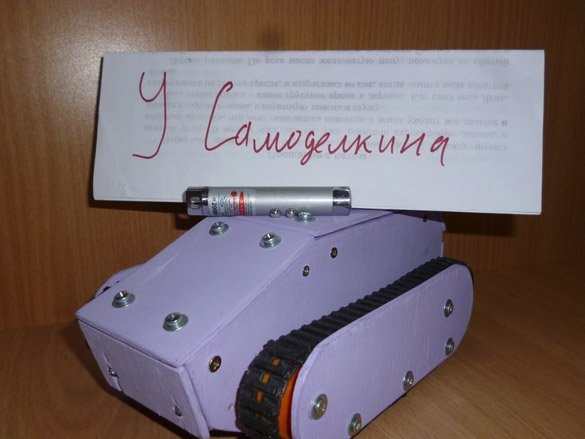
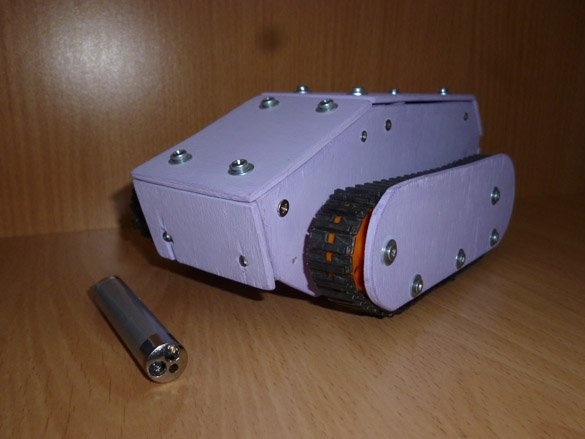
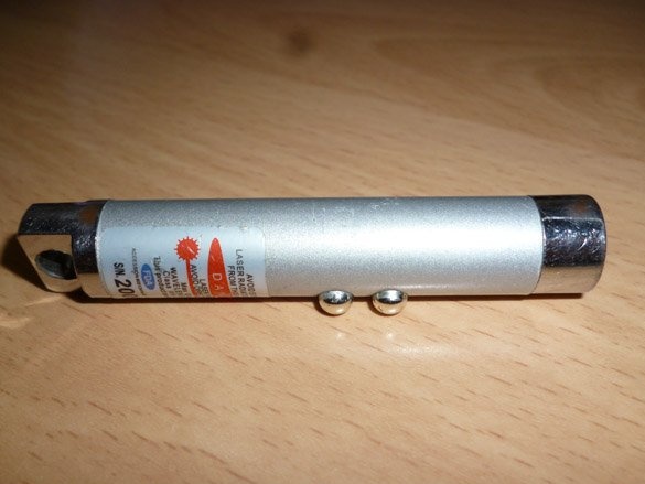
As a control tool, we will use the usual Chinese laser pointer with a red beam:
Step 4 Editing a sketch.
To edit and fill in the sketch, you need to download the Arduino IDE. We go to the official project site and download the latest version.
No additional libraries are needed.
Photoresistors are far from the most accurate measuring device. Its characteristics, in practice, depend on a large number of factors. Therefore, for proper operation, it is necessary to adjust each photoresistor. We will correct the readings by editing the sketch using the Arduino IDE and port monitor. Open the sketch:
Let's start with the front photo resistors. At the very bottom, uncomment the three lines for the front sensors:
//Serial.print(senLF); // Uncomment To Adjust Front Photoresistors
//Serial.print ("");
//Serial.println(senRF);
And also you need to add a pause in order to have time to view them. Therefore, uncomment this line too:
// delay (500);
Fill the sketch. We put the tank on the table, when lighting the room with an ordinary chandelier, the table lamp should not be turned on. And open the Arduino IDE port monitor. Under normal lighting, the readings should be greater than 500, and at the same time approximately the same for both sensors. Let's try to move the laser pointer in front of the nose of the tank. Indications should vary. The closer the point, the smaller the numbers should be. They should be in the range from 80 (at the maximum proximity of the point) to 500 (at a distance of about 2-3 cm.).
To adjust, use the variables in the sketch:
int corLF = 0; // Correction variables, front left
int corRF = 30; // Front Right
Correction variables can be either positive (added to the sensor) or negative (subtracted from the readings). Changing these variables, again fill in the sketch and see that the indicators are in the ranges we need.
Now do the same with the rear photoresistors. To do this, comment out the lines for the front sensors and uncomment the following lines:
//Serial.print(senLB); // Uncomment to adjust the rear photoresistors
//Serial.print ("");
//Serial.println(senRB);
A pause should be left uncommented. We carry out the same measurements, only now with photoresistors at the back. And write the correcting variables:
int corLB = 0; // Rear Left
int corRB = 35; // Rear Right
To make it clear how everything works. The left front sensor controls the movement of the right track forward, and the right front sensor controls the left track forward, and so on. Sensor readings are adjusted according to the following formulas:
senLF = (analogRead (senLFPin) + corLF); // front left
senRF = (analogRead (senRFPin) + corRF); // Front Right
senLB = (analogRead (senLBPin) + corLB); // Rear Left
senRB = (analogRead (senRBPin) + corRB); // Rear Right
Where, senLF, senRF, senLB, sen RB - corrected readings
analogRead (senLFPin), (analogRead (senRFPin), (analogRead (senLBPin), (analogRead (senRBPin) - “clean” sensor readings
colLF, colRF, corLB, corRB - correction variables.
And then the readings are translated into the speed of rotation of the opposite track:
walRF = map (senLF, 80, 500, 100, 255);
walLF = map (senRF, 80, 500, 100, 255);
walRB = map (senLB, 80, 500, 100, 255);
walLB = map (senRB, 80, 500, 100, 255);
If you can’t correct the readings in any way, change the maximum and minimum readings at which the tracks begin to move. These are the numbers 80 and 500 in the conversion lines written above.
Having finished all the procedures, comment out all these lines, and fill in the sketch. Now the tank will ride behind the red dot of the laser pointer.