
Greetings the inhabitants of our site!
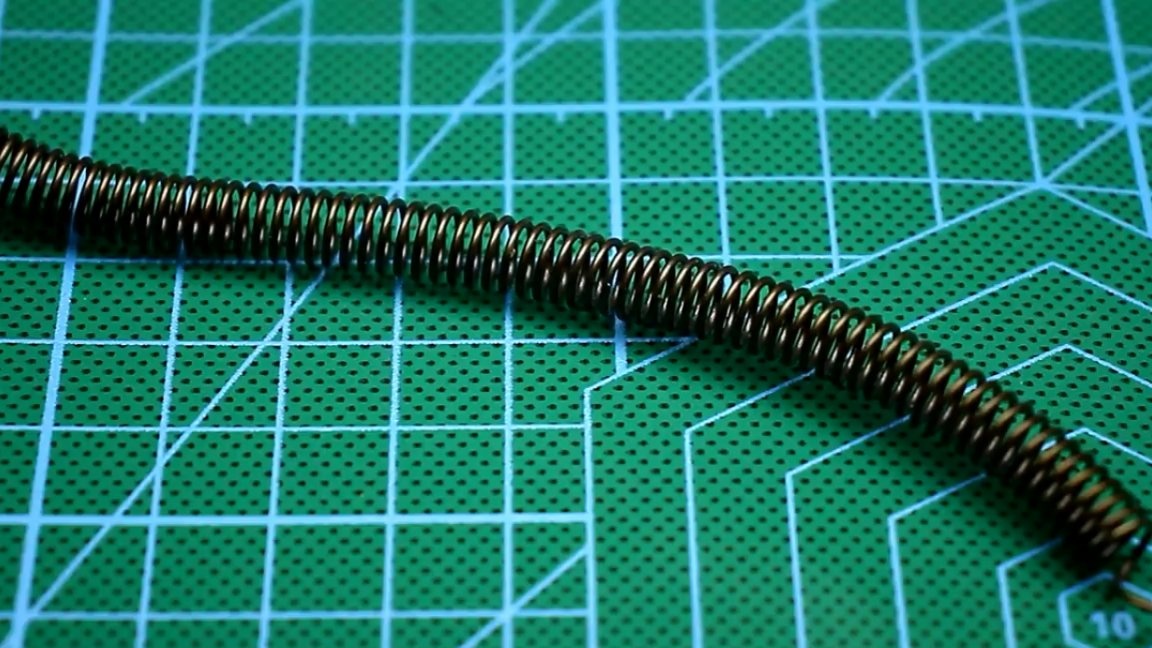
We all know that Chinese online stores and sites sell electronic DIY kits The schemes by which they are made were not created by the Chinese, or even by Soviet engineers. Any amateur radio operator will confirm that during everyday searches very often you have to load certain schemes to identify the output characteristics of the latter. The load may be a conventional lamp, resistor or nichrome heating element.
Often, those who are studying power electronics are faced with the problem of finding the right load. Checking the output characteristics of a particular power supply, whether it is home-made or industrial, the load is required, moreover, the load is adjustable. The easiest solution to this problem is to use training rheostats as a load.
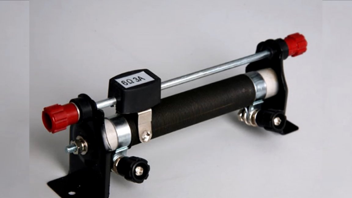
But finding powerful rheostats these days is problematic, besides rheostats are also not rubber, their resistance is limited. There is only one solution to the problem - electronic load. In an electronic load, all power is allocated to power elements - transistors. In fact, electronic loads can be done at any power, and they are much more universal than a conventional rheostat. Professional laboratory electronic loads cost a ton of money.

The Chinese, as always, offer countless analogues. One of the options for such a load of 150W costs only $ 9-10, this is a little for the device, which in importance is probably comparable with a laboratory power supply.

In general, the author of this homemade AKA KASYAN, chose to make his own version. Finding a device diagram was not difficult.
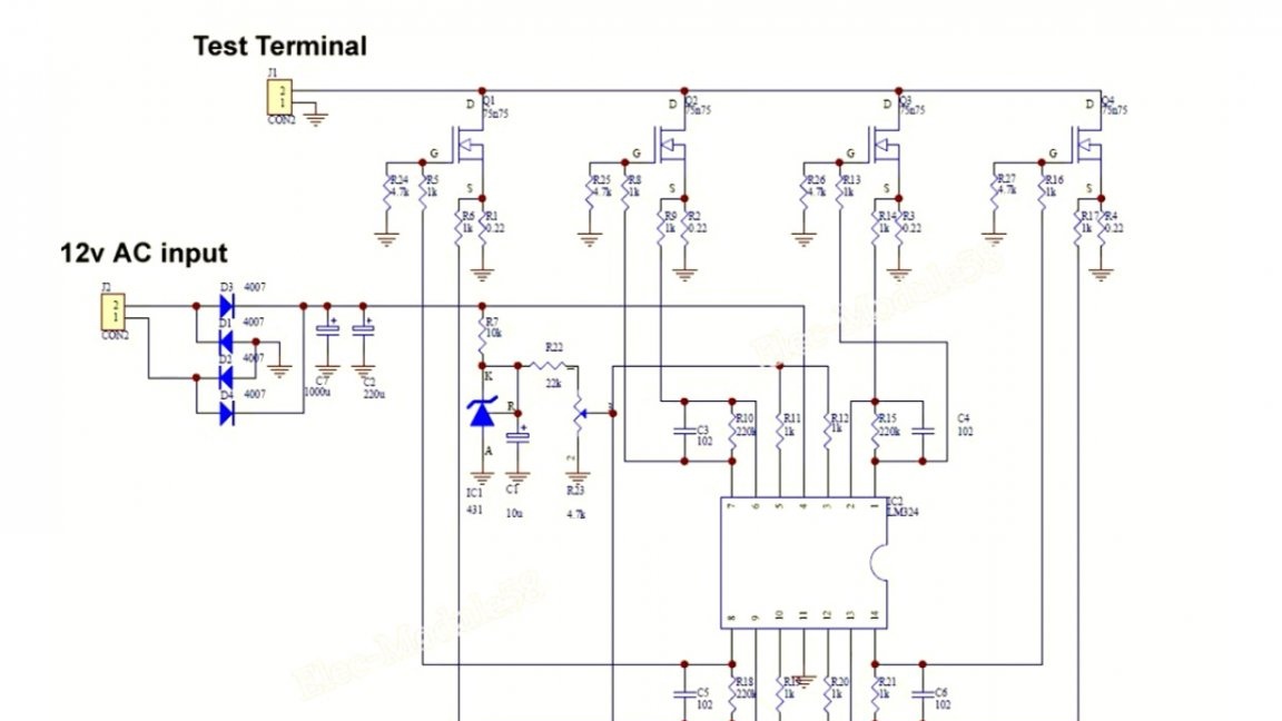
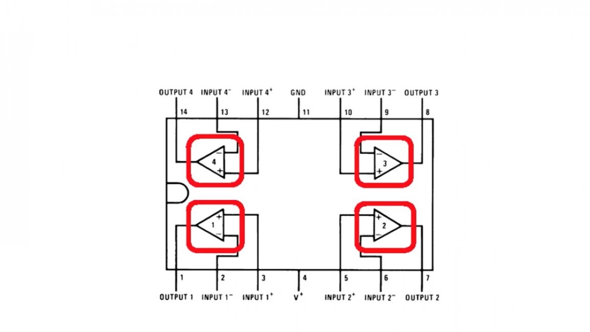
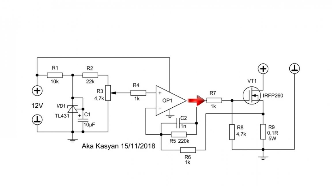
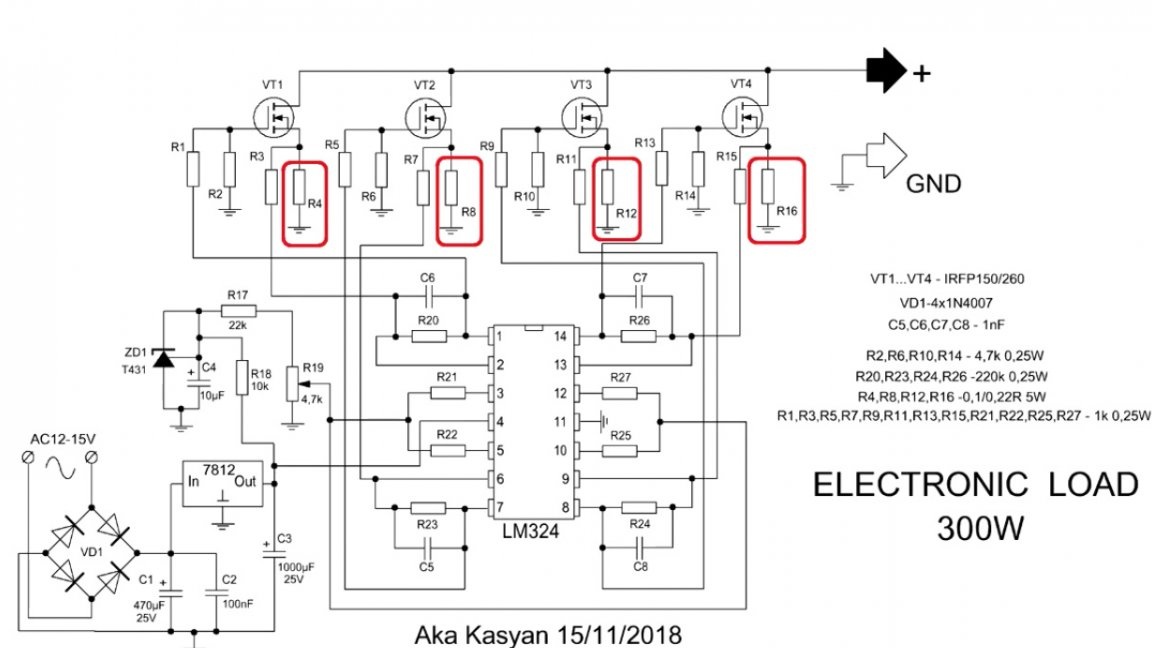
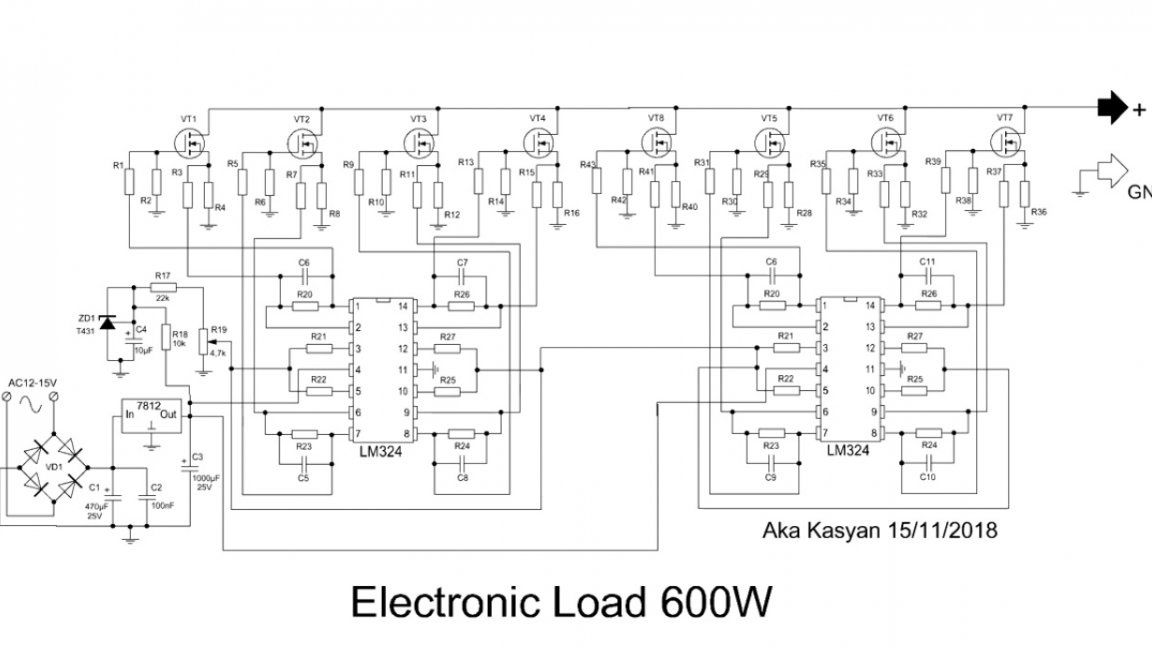
This circuit uses an operational amplifier chip lm324, which includes 4 separate elements.
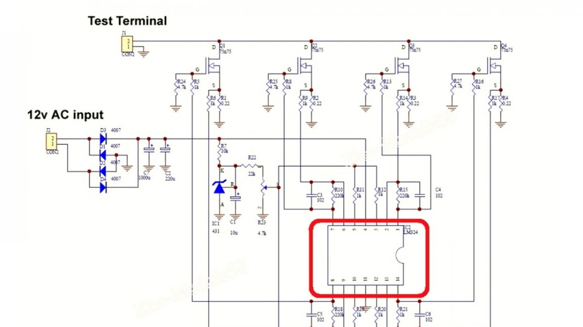
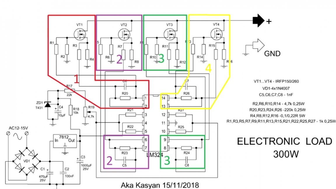
If you look closely at the circuit, it immediately becomes clear that it consists of 4 separate loads that are connected in parallel, due to which the overall load capacity of the circuit is several times greater.
This is a conventional current stabilizer on field effect transistors, which can be replaced without problems by bipolar transistors of reverse conductivity. Consider the principle of operation on the example of one of the blocks. The operational amplifier has 2 inputs: direct and inverse, well, 1 output, which in this circuit controls a powerful n-channel field effect transistor.
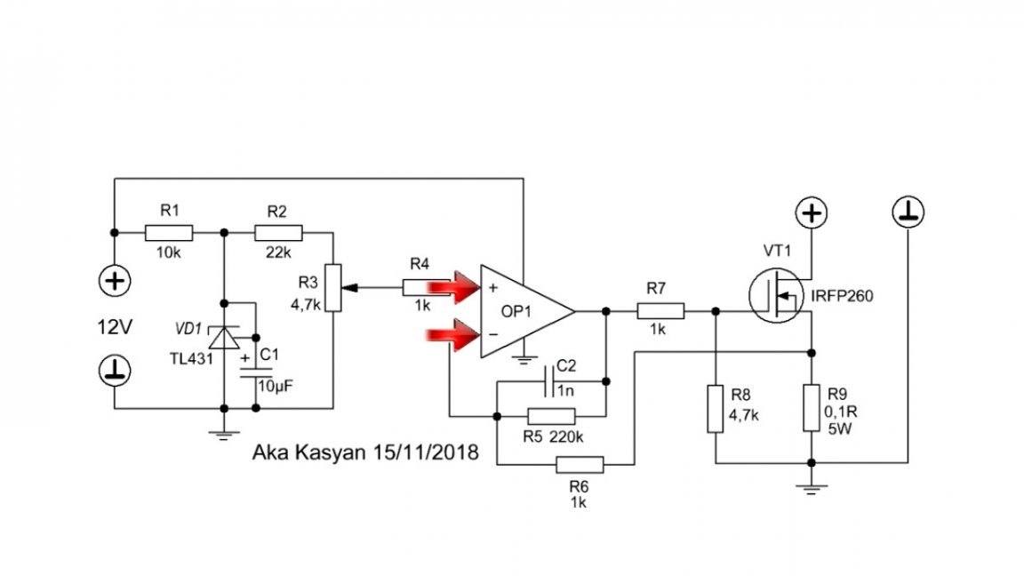
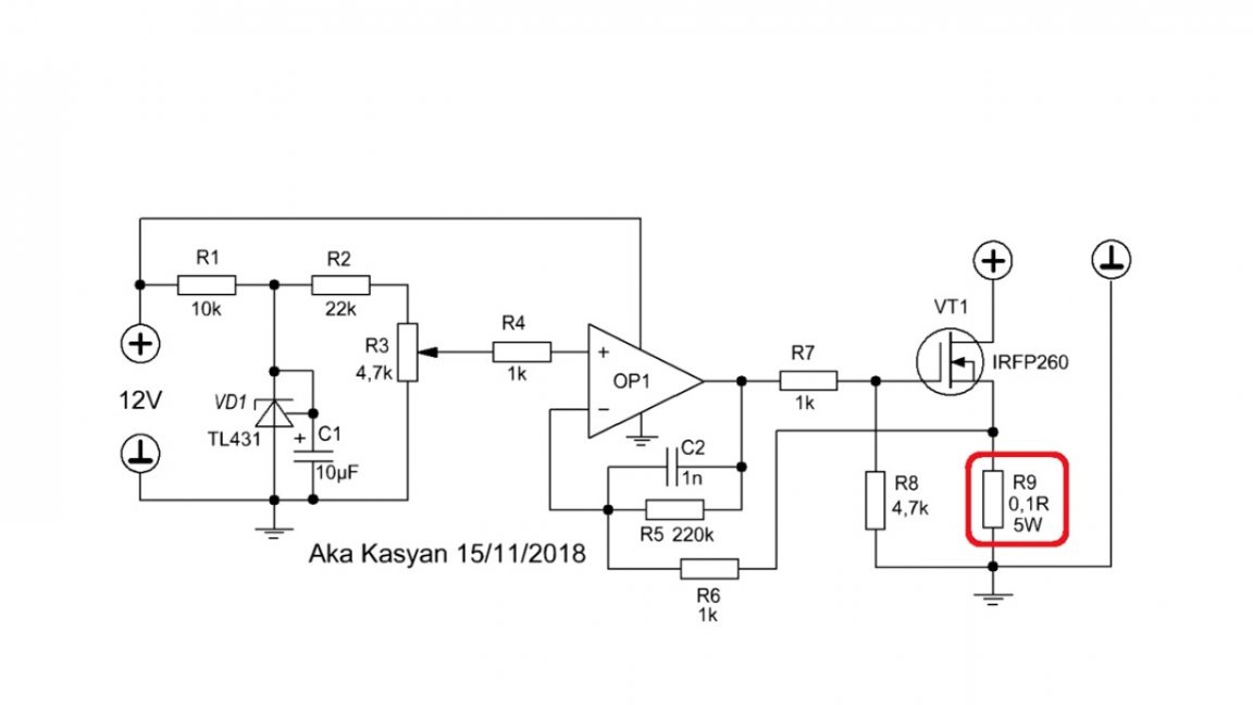
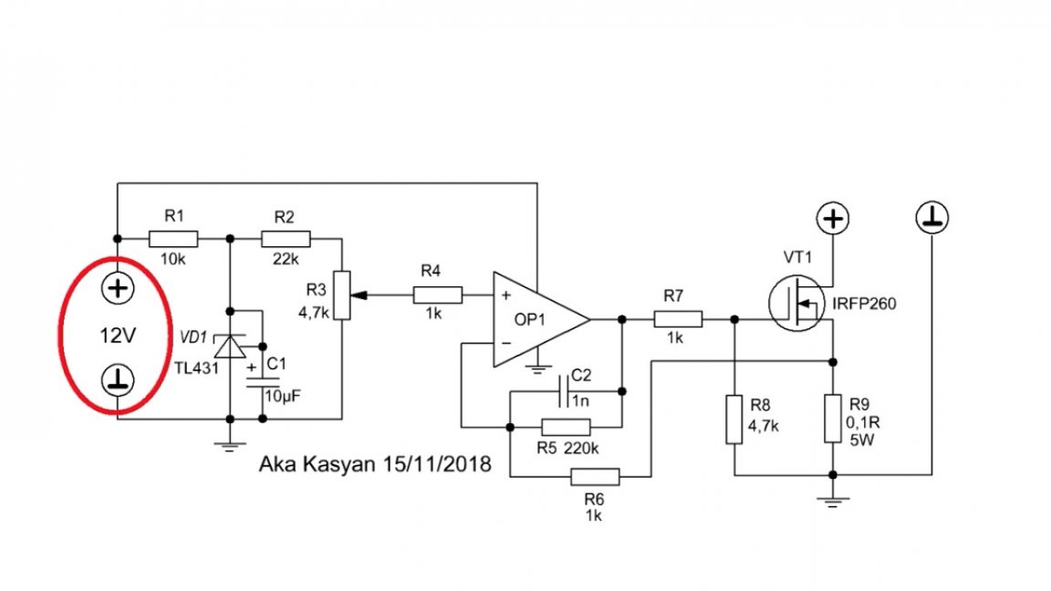
We have a low-resistance resistor as a current sensor. For the load to work, a low-current 12-15V power supply is needed, or rather it is needed for the operation of an operational amplifier.
The operational amplifier always strives to ensure that the voltage difference between its inputs is zero, and does this by changing the output voltage. When the power supply is connected to the load, a voltage drop will form on the current sensor, the greater the current in the circuit, the greater the drop on the sensor.
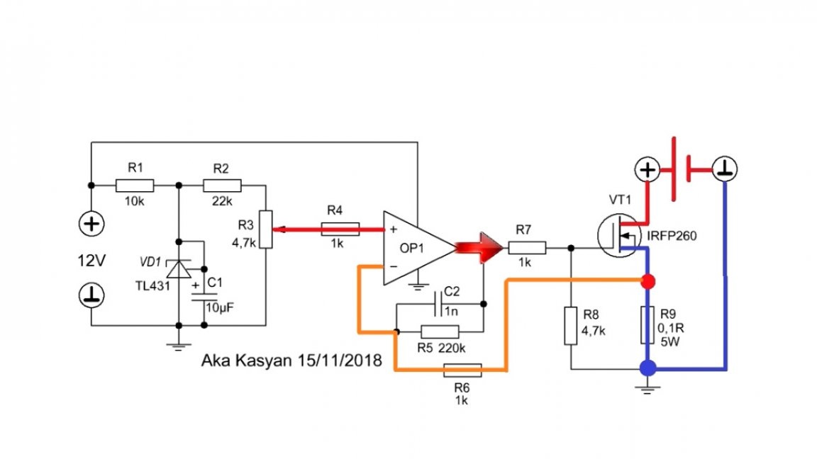
Thus, at the inputs of the operational amplifier we get the voltage difference, and the operational amplifier will try to compensate for this difference by changing its output voltage by smoothly opening or closing the transistor, which leads to a decrease or increase in the resistance of the transistor channel, and, consequently, the current flowing in the circuit will change .
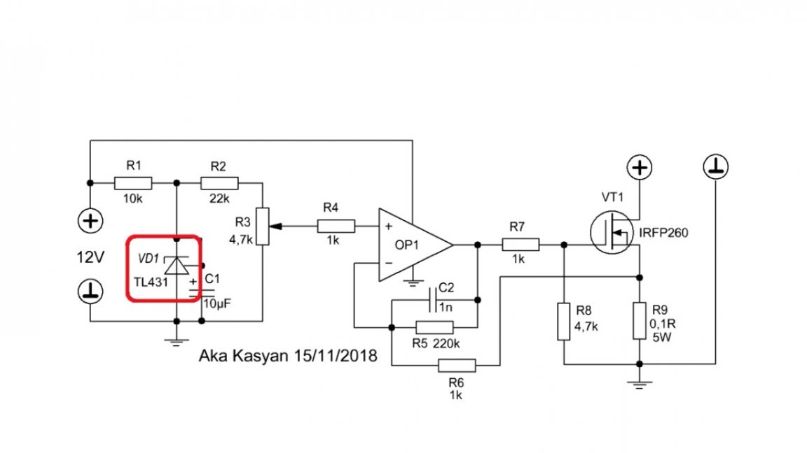
In the circuit we have a reference voltage source and a variable resistor, the rotation of which gives us the opportunity to force change the voltage at one of the inputs of the operational amplifier, and then the aforementioned process occurs, and as a result, the current in the circuit changes.
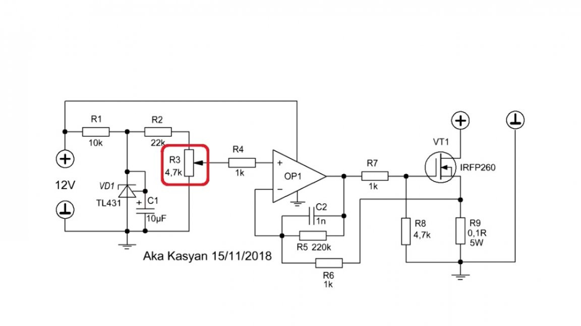
The load runs in linear mode. Unlike a pulsed one, in which the transistor is either fully open or closed, in our case we can make the transistor open as much as we need. In other words, smoothly change the resistance of its channel, and, therefore, change the circuit current literally from 1 mA. It is important to note that the current value set by the variable resistor does not change depending on the input voltage, that is, the current is stabilized.
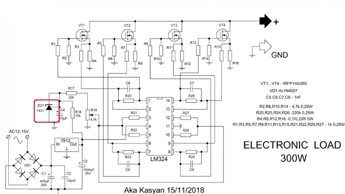
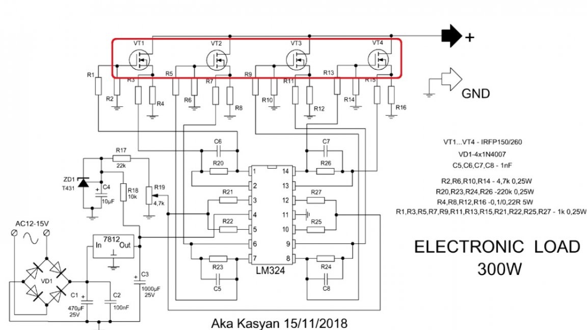
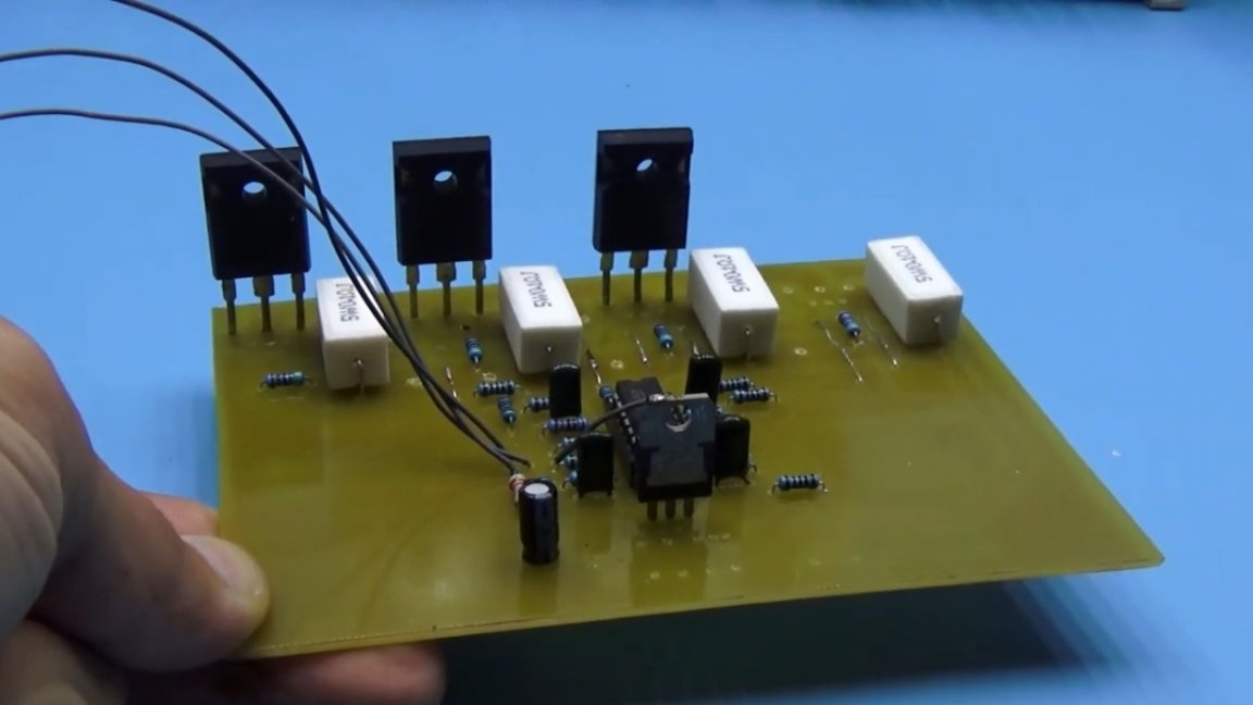
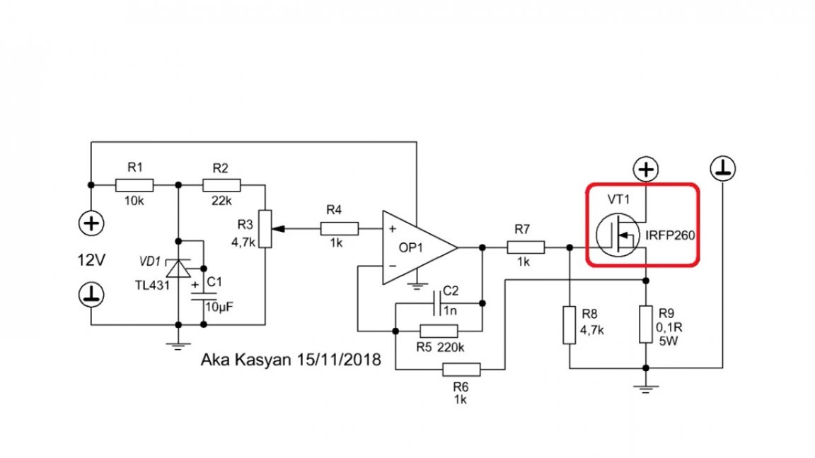
In the scheme we have 4 such blocks. The reference voltage is generated from the same source, which means that all 4 transistors will open evenly. As you noticed, the author used powerful field keys IRFP260N.
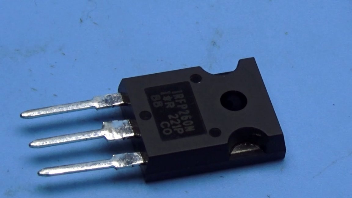
These are very good transistors at 45A, 300W power. In the circuit we have 4 such transistors and in theory such a load should dissipate up to 1200W, but alas. Our circuit operates in linear mode. No matter how powerful the transistor is, in linear mode everything is different. The dissipation power is limited by the transistor case, all the power is released in the form of heat on the transistor, and it must have time to transfer this heat to the radiator. Therefore, even the coolest transistor in linear mode is not so cool. In this case, the maximum that the transistor in the TO247 package can dissipate is somewhere around 75W of power, that's it.
We've sorted out the theory, now let's move on to practice.
Printed circuit board was developed in just a couple of hours, the wiring is good.

The finished board needs to be tinned, the power paths reinforced with a single-core copper wire, and everything is plentifully filled with solder to minimize losses on the resistance of the conductors.
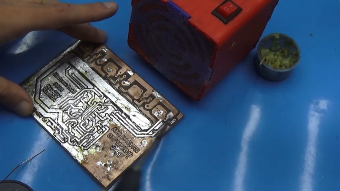
The board provides seats for installing transistors, both in the TO247 and TO220 package.
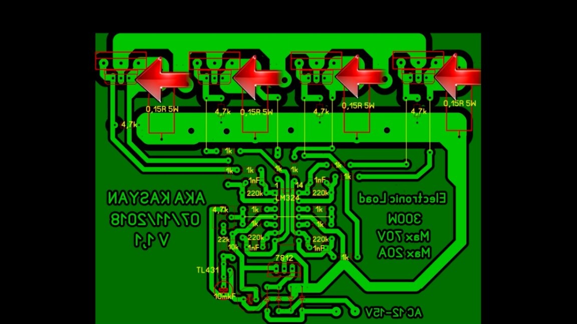
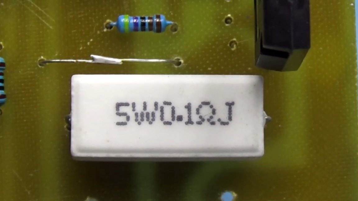
In the case of using the latter, you need to remember the maximum that the TO220 chassis is capable of is a modest 40W of power in linear mode. Current sensors are low-resistance 5W resistors with a resistance of 0.1 to 0.22 ohms.
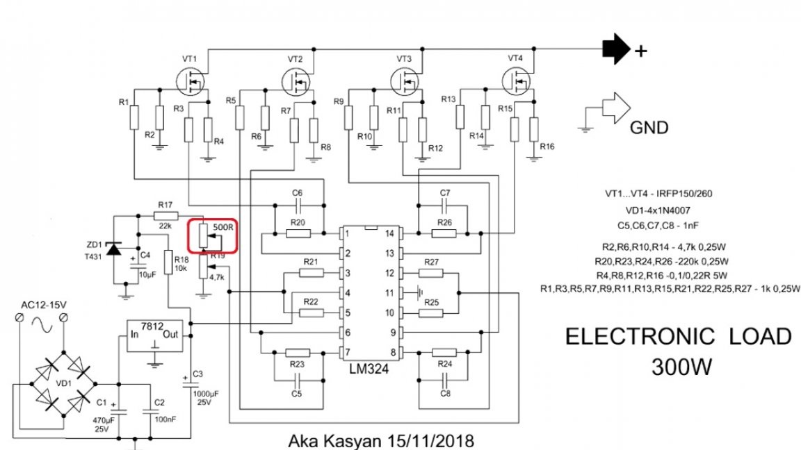
Operational amplifiers are preferably mounted on a socket for solderless mounting. For more accurate current regulation, add another 1 low-resistance resistor to the circuit. The first will allow for coarse adjustment, the second smoother.
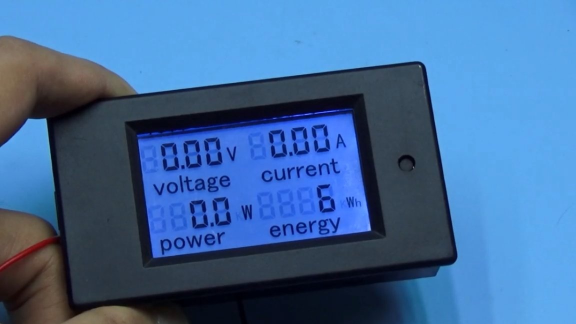
Precautionary measures. The load has no protection, so you need to use it wisely. For example, if transistors of 50V are in the load, then it is forbidden to connect the tested power supplies with a voltage above 45V. Well, that was a small margin. It is not recommended to set the current value to more than 20A if the transistors are in the TO247 and 10-12A cases, if the transistors are in the TO220 case. And, perhaps, the most important point is not to exceed the permissible power of 300W, if transistors in the housing from TO247 are used. To do this, it is necessary to integrate a wattmeter into the load in order to monitor the dissipated power and not exceed the maximum value.
The author also strongly recommends using transistors from the same batch to minimize the spread of characteristics.
Cooling. I hope everyone understands that 300W of power will go stupidly for heating transistors, it's like a 300W heater. If heat is not effectively removed, then Khan transistors, so we install transistors on a massive one-piece radiator.

The place where the key substrate is pressed against the radiator must be thoroughly cleaned, degreased and polished. Even small bumps in our case can ruin everything. If you decide to spread thermal grease, then do it with a thin layer, using only good thermal grease. You do not need to use thermal pads, you also do not need to isolate the key substrates from the radiator, all this affects the heat transfer.
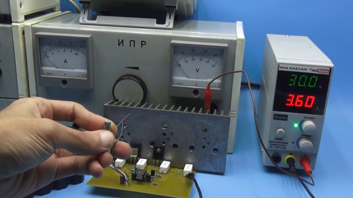
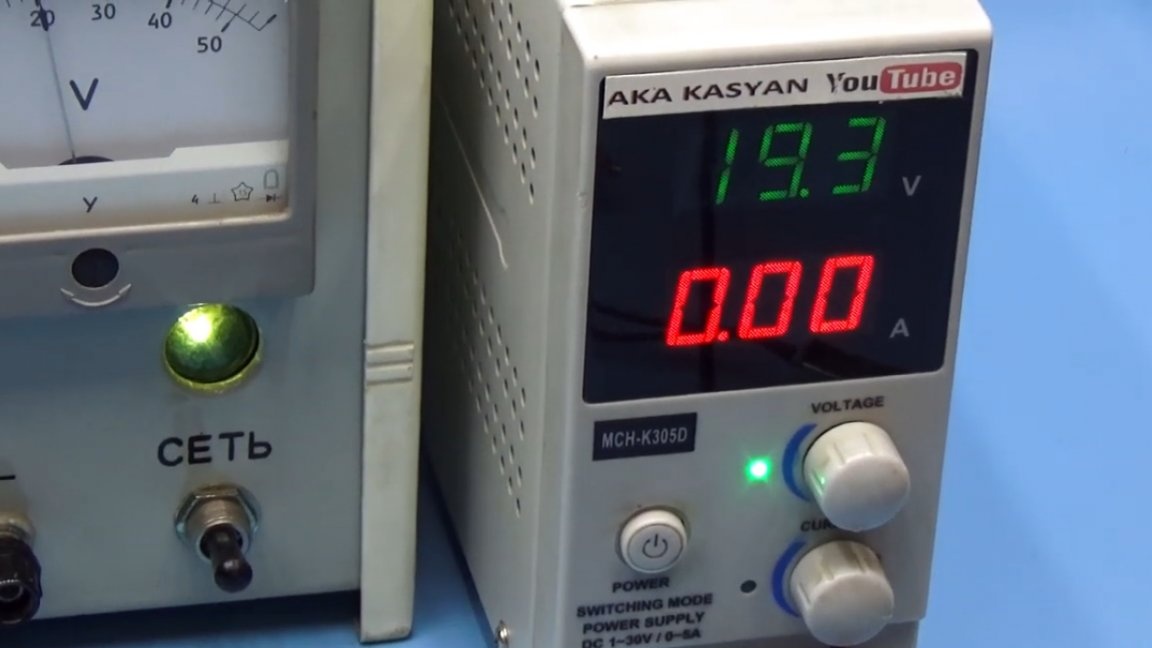
Well, now, finally, let's check the work of our load. We will load here such a laboratory power supply, which gives a maximum of 30V at a current of up to 7A, that is, the output power is about 210W.
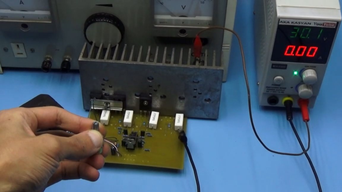
In the load itself, in this case, 3 transistors are installed instead of 4 ex, so we won’t be able to get all 300W of power, it's too risky, and the lab will not give out more than 210W. Here you can notice the 12-volt battery.

In this case, it is only for powering the operational amplifier. We gradually increase the current and reach the desired level.
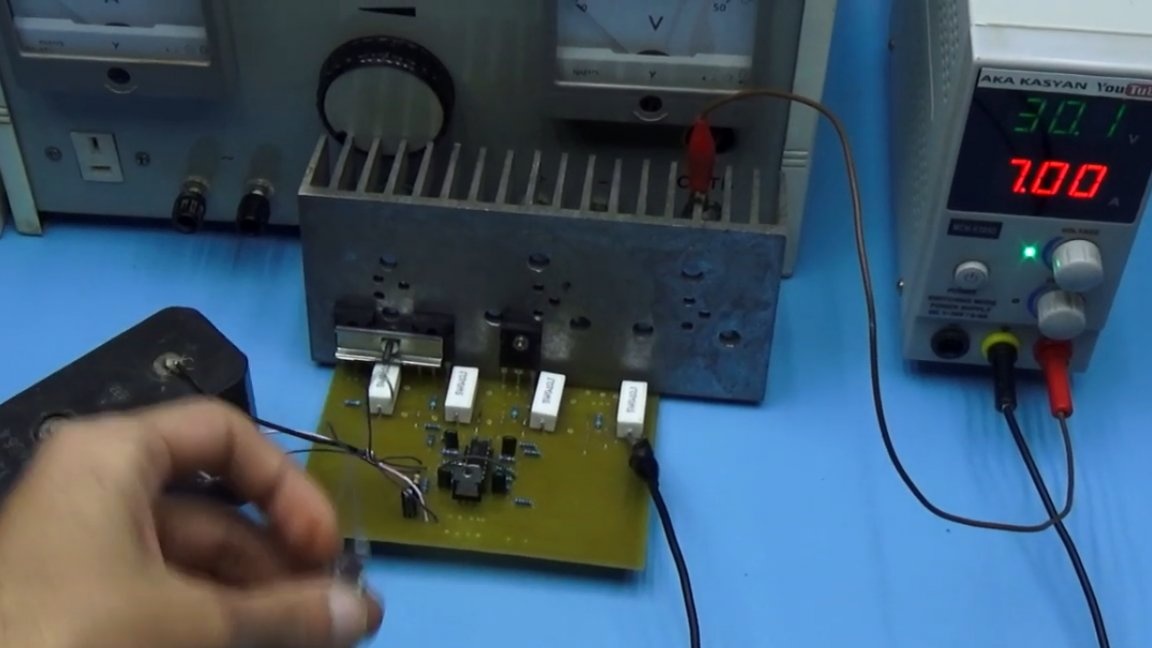
30V, 7A - everything works fine. The load withstood despite the fact that the author’s keys from different parties were painfully dubious, but they were original if they didn’t burst at once.
Such a load can be used to check the power of computer power supplies and beyond. And also in order to discharge the battery, to identify the capacity of the latter. In general, hams will appreciate the benefits of electronic load. The thing is really useful in the radio amateur laboratory, and the power of such a load can be increased even up to 1000W by including several such boards in parallel. The 600W load scheme is presented below:
By clicking on the "Source" link at the end of the article, you can download the project archive with a circuit and a printed circuit board.
Thank you for attention. See you soon!
Video: