
Thanks to the photo relay, the light switches almost disappeared from the porches - it is controlled automatically depending on the ambient light. It is convenient to study the device and the operation of this device on a breadboard, one of the variants of which was invented by the author of Instructables under the nickname afzalrehmani.
As in a real photo relay, the light sensor in the layout is a photoresistor - a component whose resistance varies depending on the intensity of the light incident on it. The dark resistance of a photoresistor is called its resistance, which is obtained in complete darkness. In bright lighting, the resistance of the photoresistor decreases so much that you can directly control a small electromagnetic or thermal relay. But today, between the photoresistor and the load or the relay switching it, they often place one or another electronic scheme. This reduces the heating of the component and allows you to more accurately adjust the threshold, as well as to manage without relays when controlling a low-power load. You can connect a photoresistor in any polarity.
The layout was assembled according to this scheme:
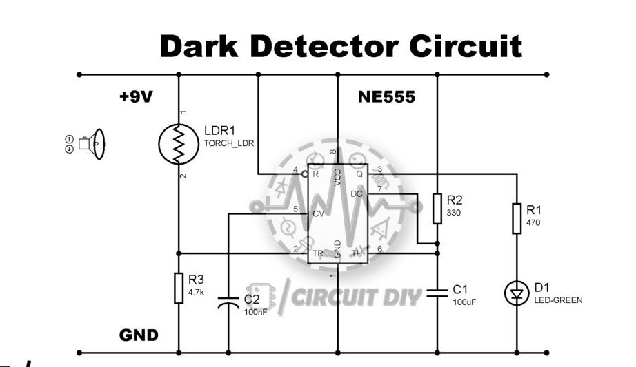
In order for the photoresistor to find a common language with the electronic circuit, it is necessary to obtain a voltage that varies smoothly depending on the change in the resistance of the component. For this afzalrehmani made a voltage divider. It consists of a series-connected photoresistor and a conventional resistor. The voltage is removed from the midpoint. It is the larger relative to the common wire, the lower the resistance of the photoresistor. If the divider is turned over, changing the photoresistor and the usual resistor in places, this dependence will be reversed. But here we need exactly the same as in the first case.
From a photo relay it is not required to smoothly adjust the brightness of artificial lighting depending on the brightness of natural light. It should turn on and off the light abruptly. If the photoresistor is loaded directly on the relay, or controls it through an electronic circuit, then the relay can serve as a threshold element. But more often this function is entrusted to an electronic circuit, which, as mentioned above, is more convenient to regulate.In afzalrehmani, it was executed on a timer 555, aka KR1006VI1. This microcircuit allows, depending on how capacitors and resistors are connected to it from the outside, to receive Schmitt triggers, odor vibrators and multivibrators. Unlike other solutions suitable for this, the parameters of the devices on the 555 timer do not change when the supply voltage changes over a fairly wide range.
The load of the timer is an LED connected via a current limiting resistor. In addition to hopping, the circuit provides inversion: when the photoresistor is lit, its resistance is small, and the voltage at the output of the divider, respectively, is large relative to the common wire, on the output of the timer it, on the contrary, is small. And vice versa. So the training photo relay works exactly like the real one: it is light around - the LED is off, dark - is on.
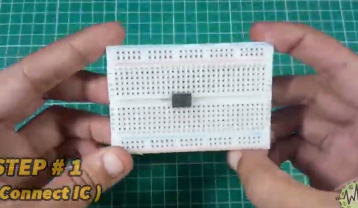
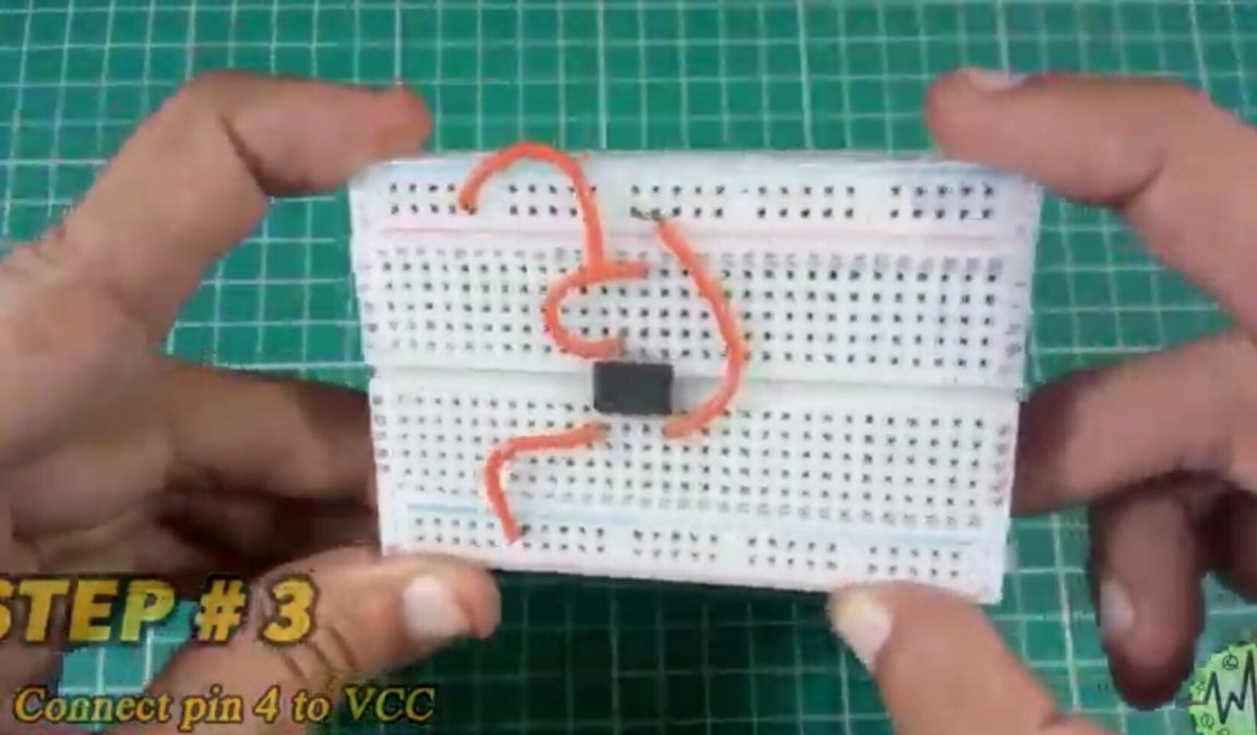
If microcircuits are installed on ordinary boards last, then on a breadboard type board it is possible in the first place - there is still no heating:
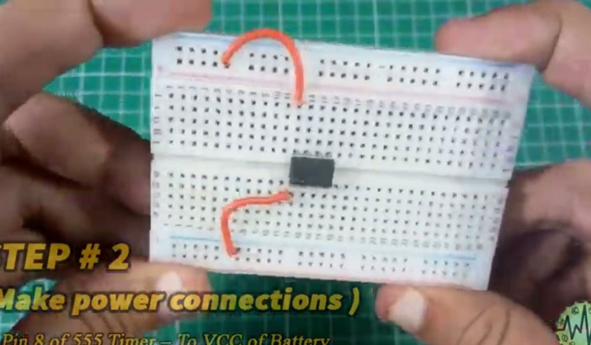
The master connects the power outputs of the microcircuit with the corresponding bus boards:
It also connects pin 4 of the microcircuit to the plus of the power supply, so that there is always a logical unit, and connects terminals 6 and 7 to each other:
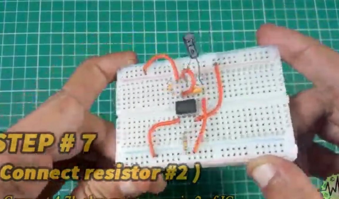
Installs resistors, capacitors and other jumpers, given that the electrolytic capacitor is polar, which means that it must be connected with a minus to the common wire. The rated voltage of this capacitor is at least 16 volts. Another capacitor, ceramic - non-polar.
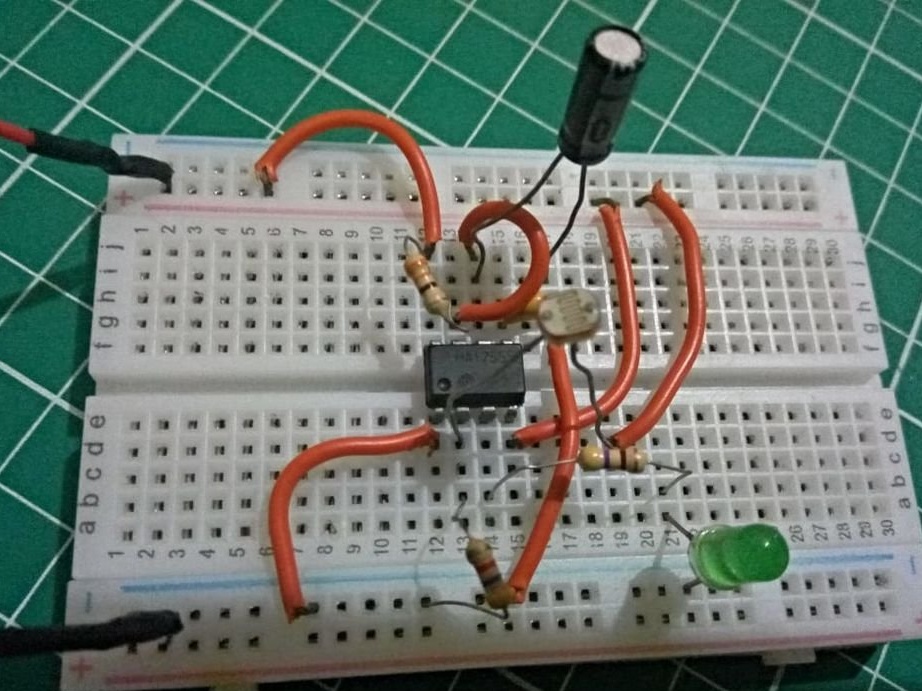
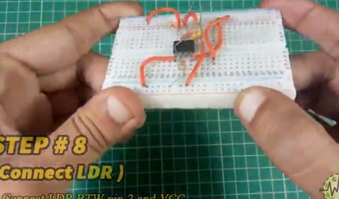
It puts a photoresistor on the board, which here and on the KDPV closes a ceramic capacitor:
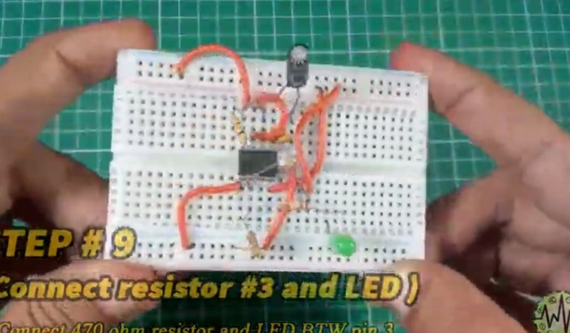
It connects an LED and a resistor connected with it in series to the output of the microcircuit. The LED is polar, the resistor is naturally not. It is necessary to direct the LED so that its light does not fall on the photoresistor:
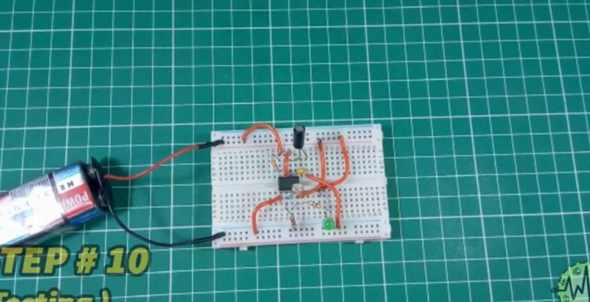
Connects the battery - here the polarity is again important. But the LED is not yet lit:
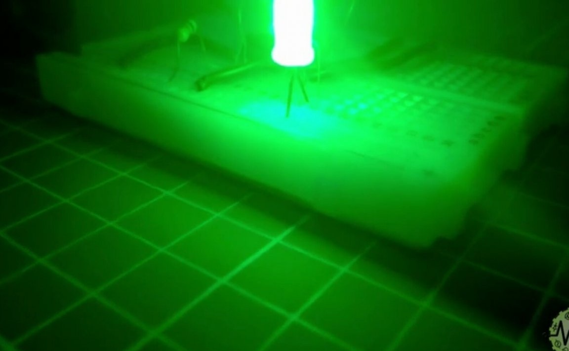
Turns off the light in the room, and the LED turns on:
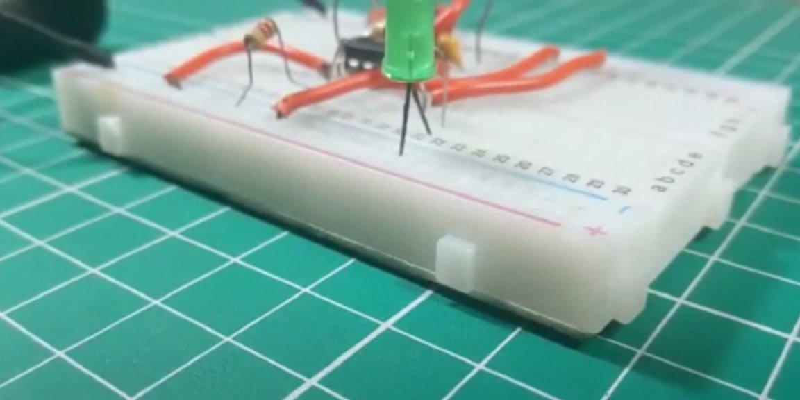
Turns on the light and the LED turns off:
After studying the datasheet on the 555 chip and connecting a voltmeter to various points of the circuit, you can figure out how it works and how the values of resistors and capacitors affect its parameters. When you are not experimenting with a photo relay, you need to turn off the power, because both the voltage divider and the microcircuit consume current even when the LED is off. Also, do not short-circuit the battery.