
Now, together with Roman, the author of the YouTube channel “Open Frime TV”, we will assemble a very interesting device, and it’s called a power factor corrector, abbreviated KKM.
It all started with the fact that up to 150V voltage began to drop in the author’s network and this created a number of problems. But the most important of them was that the working computer simply did not want to turn on, and, for information, it was turned on through a voltage regulator.
This problem must be solved, but how? The first idea was to assemble an ordinary step-up power supply with stabilization and just connect it to the input of the computer unit. In principle, the author wanted to do this and even already began to prepare a printed circuit board, but then he talked with one smart person, and he advised me to make a power factor corrector. The idea is good, but digging the Internet in search of information, unfortunately, nothing was found. On everyone’s beloved YouTube, there were only explanations of how it works, but not a single ready-made solution. And in Google, the author found only a couple of articles, of which he picked up the necessary information, and now I am ready to share it.
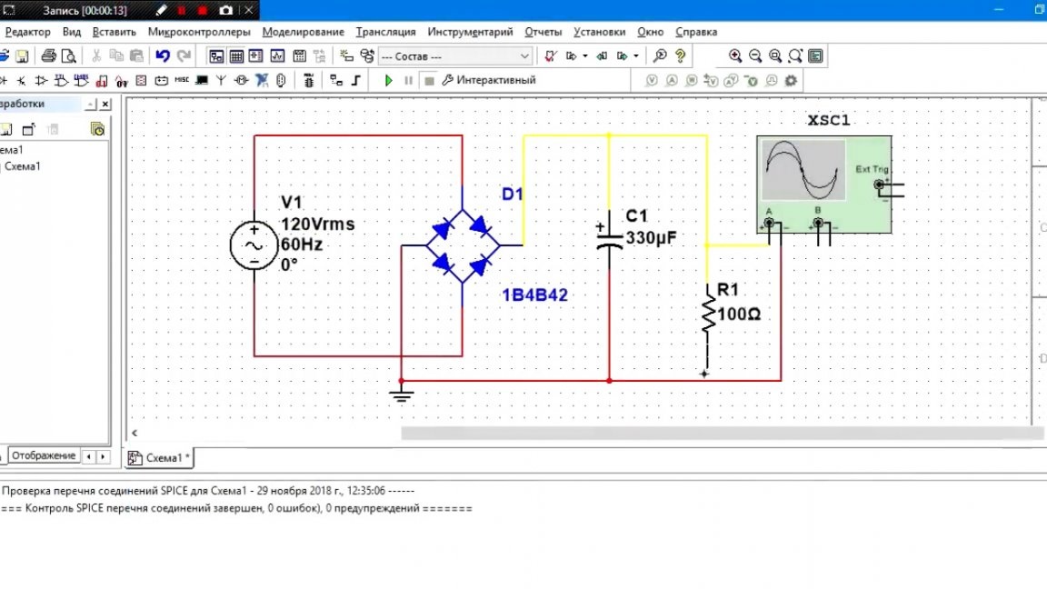
First, a few words about the operation of the device. Let's look at how the pulse block works, at least its input part. So this is the diode bridge and capacitor:
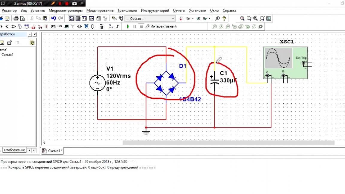
There are 2 situations:
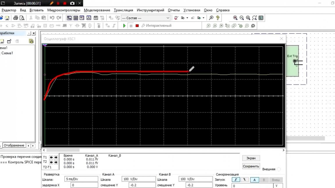
1) There is no load at the output. In this case, at the initial time, the capacitor is charged to the amplitude value of the network. And since he has nowhere to put energy, then the output will be a straight line.
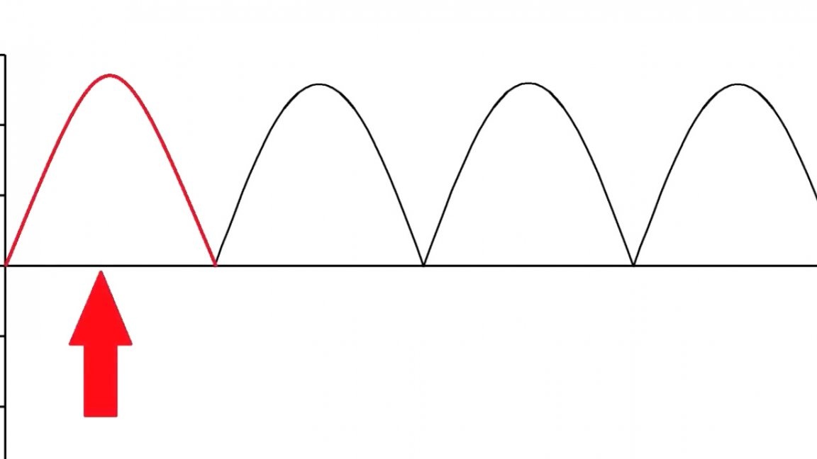
2) The second situation: we connected the load, or rather our impulse. In this case, at the initial moment of time, the conder was charged to an amplitude value, and when the half-wave of the sine wave started to decline, the conder began to discharge through the load, but it was discharged not to zero, but to a certain value. Then comes the new half-wave and the Conder recharges again.
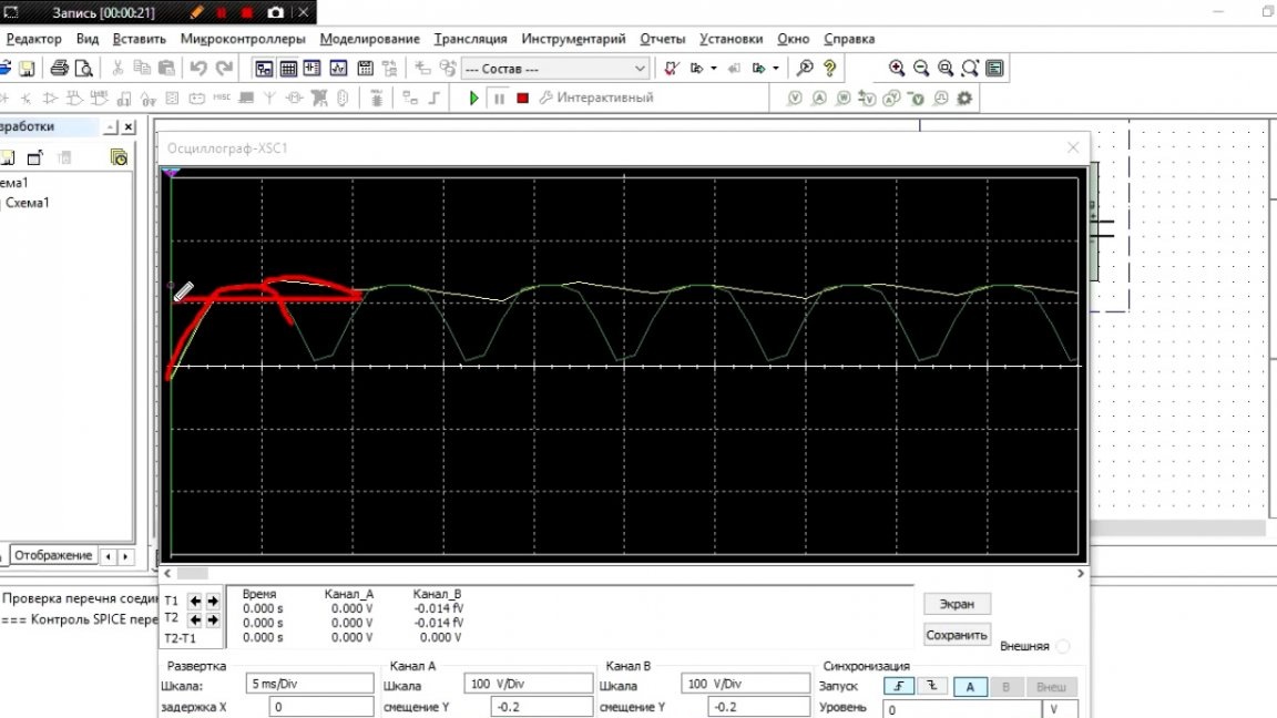
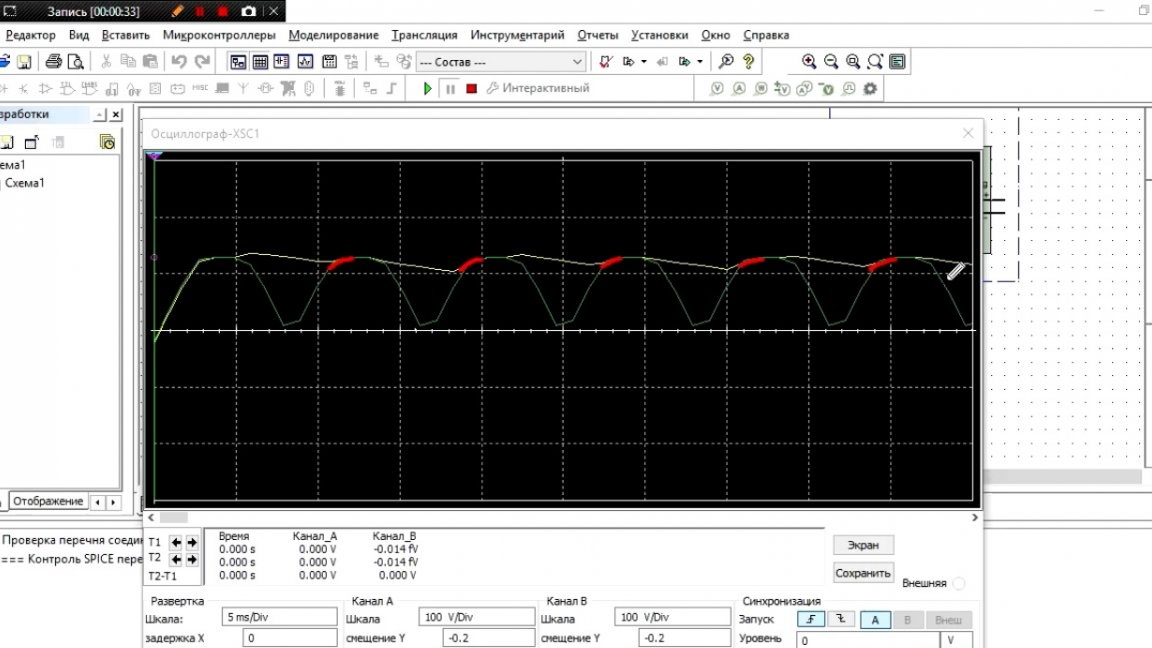
The result is such a situation that the Conder recharges only a small period of time. It is at this moment that the maximum inrush current occurs, which exceeds the nominal one several times. As you may have guessed, this is bad. What is the way out of this situation? Everything is very simple. It is necessary to put a boost converter, which will recharge the conder over almost the entire half-wave section.
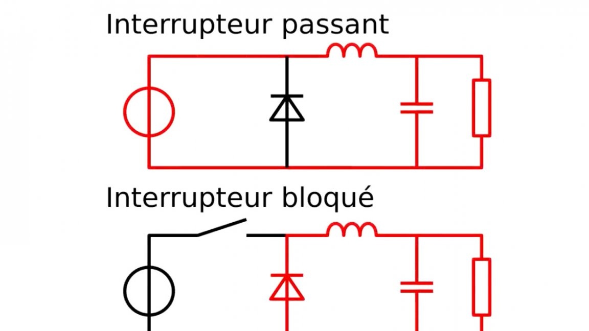
This converter is our power factor corrector.How does this work? Roughly speaking, he breaks the entire half-wave into small sections that correspond to the frequency of his work, and in each section he increases the voltage to a predetermined value.
Thus, the charge of the main capacitor occurs throughout the half-wave, thereby removing current surges, and our pulse generator looks like a purely active load for the network.
There is also another feature of the corrector, it is that it can work normally even with an incoming voltage of 90 V. It still needs to increase the voltage, be it with an amplitude of 310 V or 150 V.

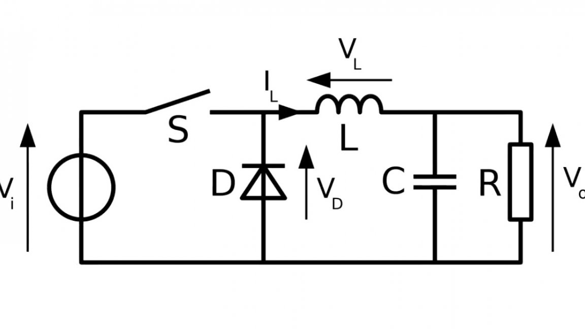
Well, we briefly familiarized ourselves with the principle of operation of this device, and now let's move on to considering the circuit.
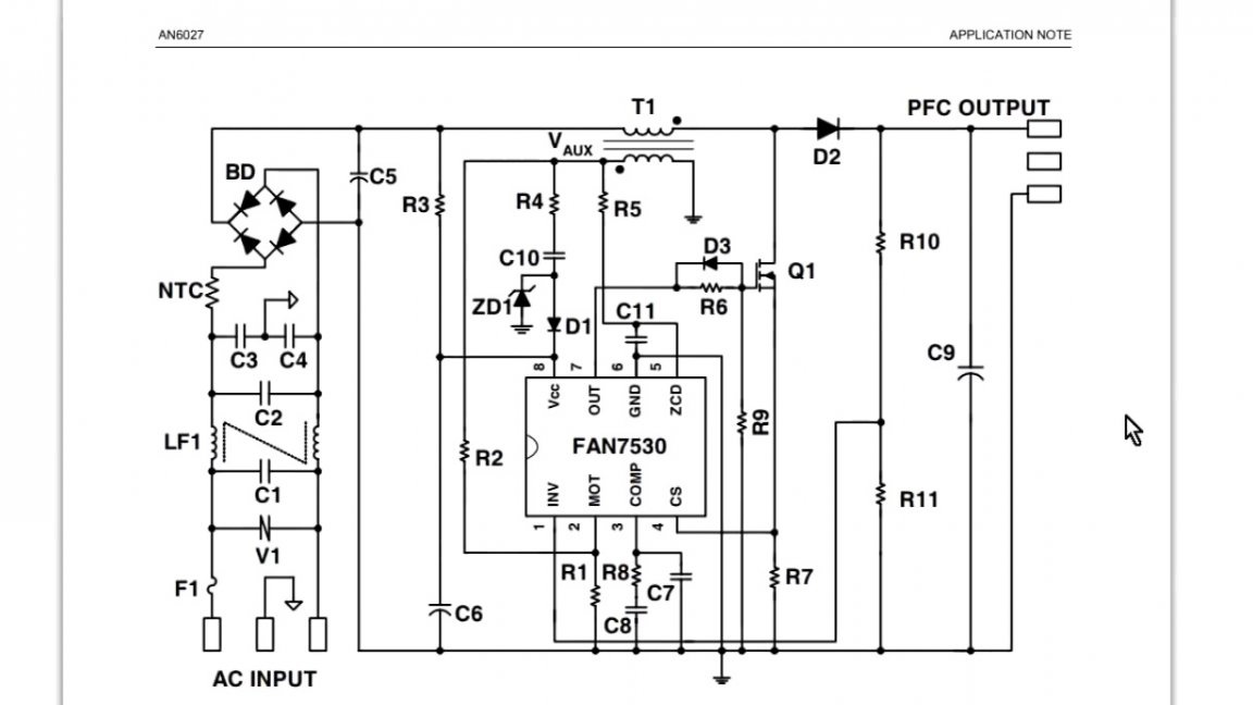
It was taken from a datasheet; the author did not contribute anything to it. As you can see, there are few elements, this is good, it will be easier to part the circuit board.
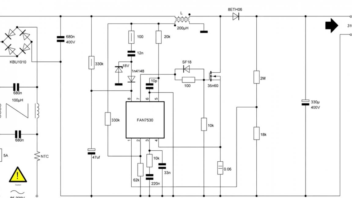
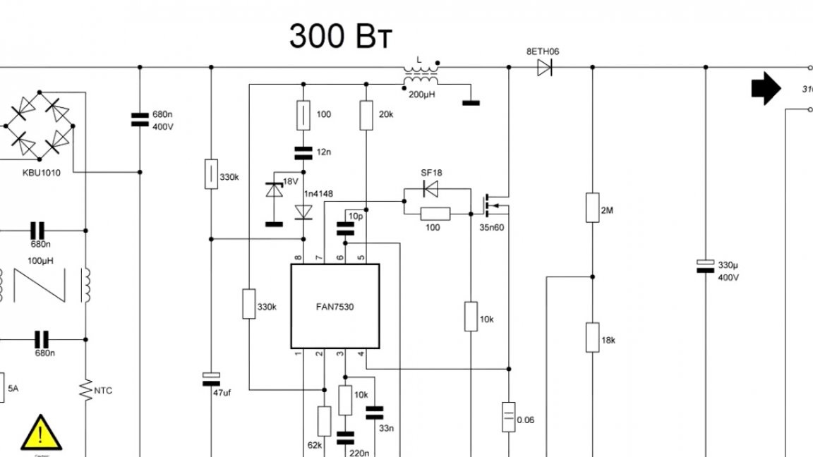
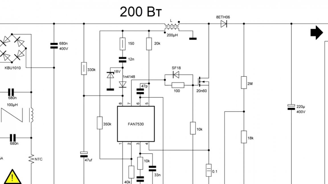
It is also worth considering important points of the circuit: first, some element ratings will differ for different capacities, this must be taken into account; the second is the output voltage. If you are doing KKM for a computer power supply, then you need to choose a voltage of 310V. And if you count the block from scratch, then it is better to take a voltage in the region of 380V.
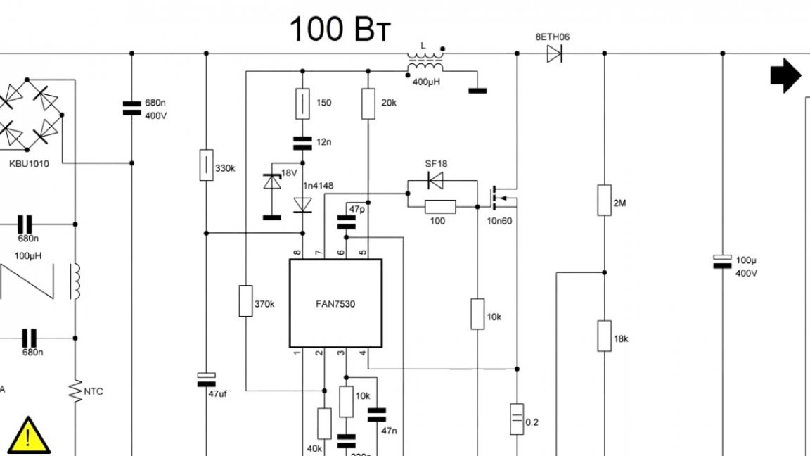
The value of the output voltage is regulated by a voltage divider on these resistors:
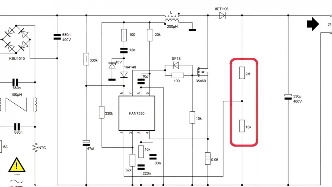
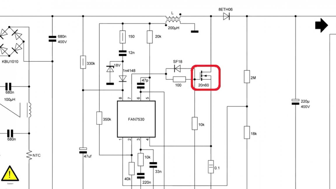
From such a calculation that with a rated output voltage on the divider was 2.5V. As mentioned earlier, different elements require different capacities. For a power of 100W, a 10n60 transistor is needed, and for 300W, 28n60 is already needed. But it’s better to take with a margin of 35n60, this will definitely withstand the required load.

Move on. Diode.
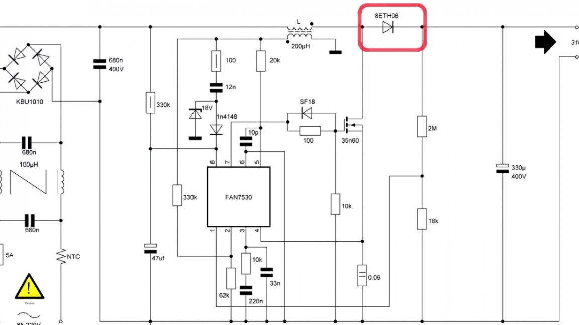
It must be ultrafast for a voltage of at least 600V and a current of 5 amperes or higher. An important role is played by the output capacitor. Roughly it can be calculated from considerations, 1uF per 1W of output power.
There is a choke, we will consider its winding later.
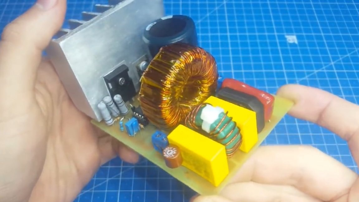
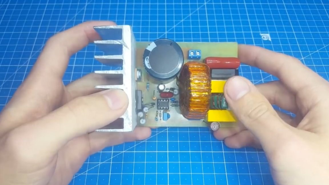
We pass to the printed circuit board. It turned out rather big, but this is all due to the large size of the capacitor and inductor.
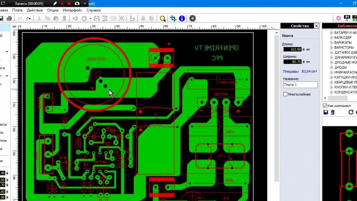
As you can see, the author parted the board without a single jumper and everything on the introductory details for ease of repetition. Say nothing more about the signet, let's go poison the board.
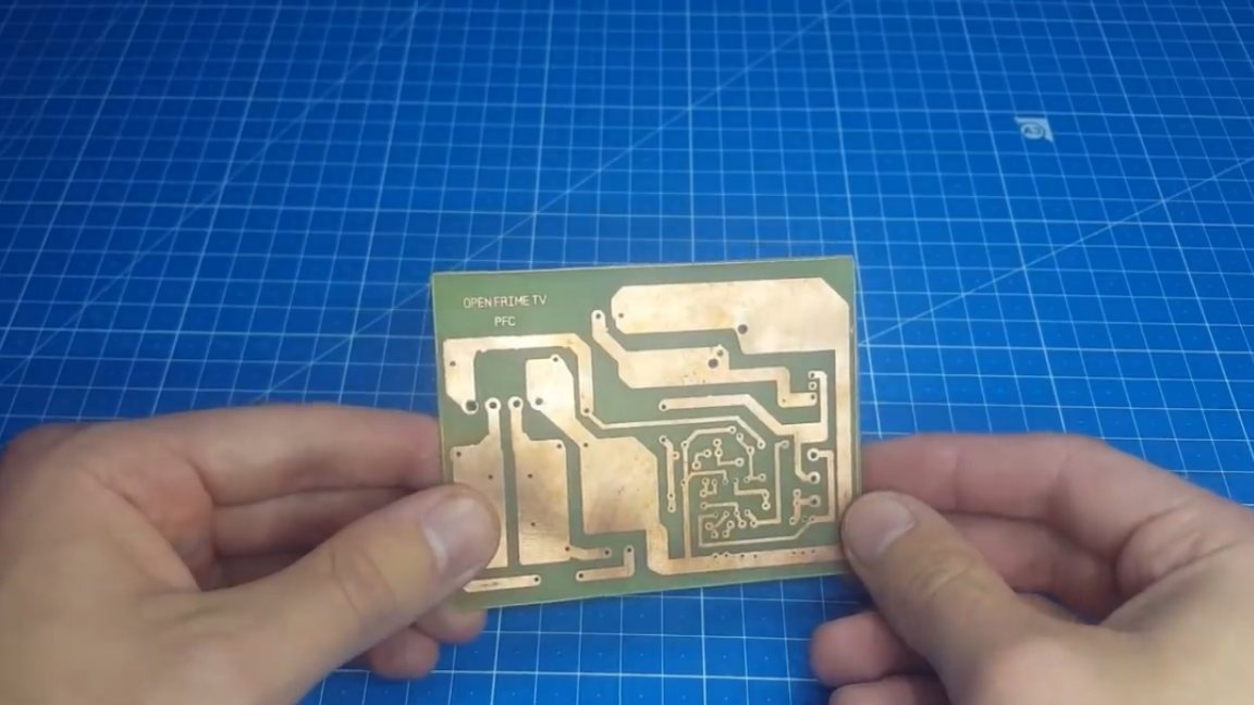
We corroded the board, drilled holes on the drilling machine, and now we proceed to sealing parts.
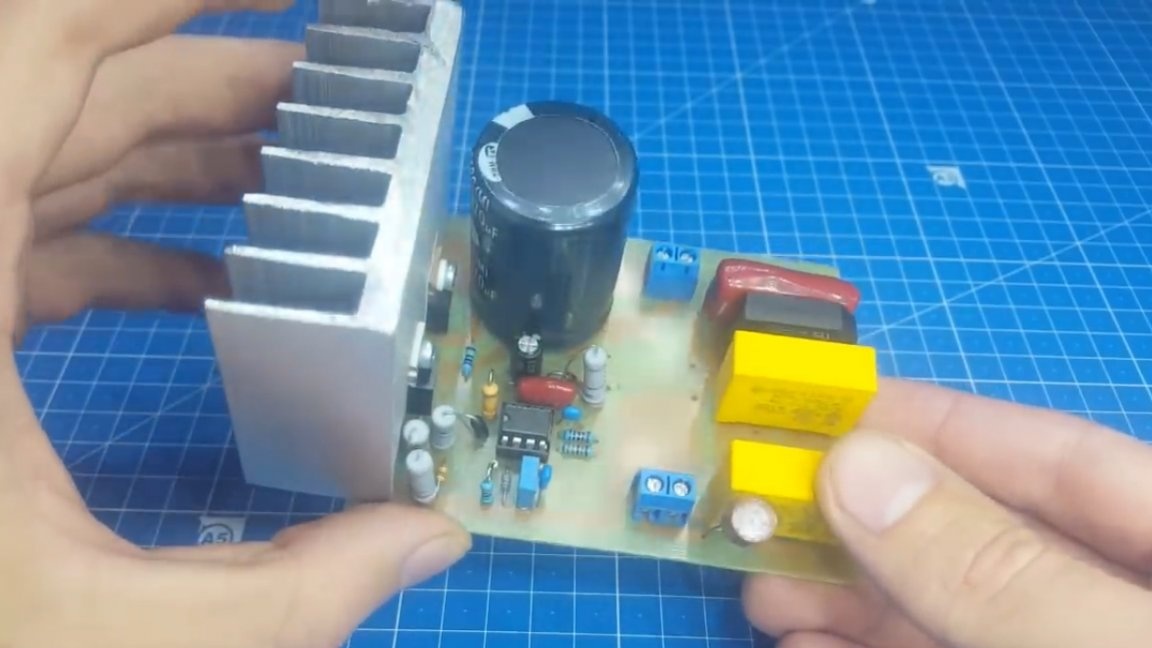
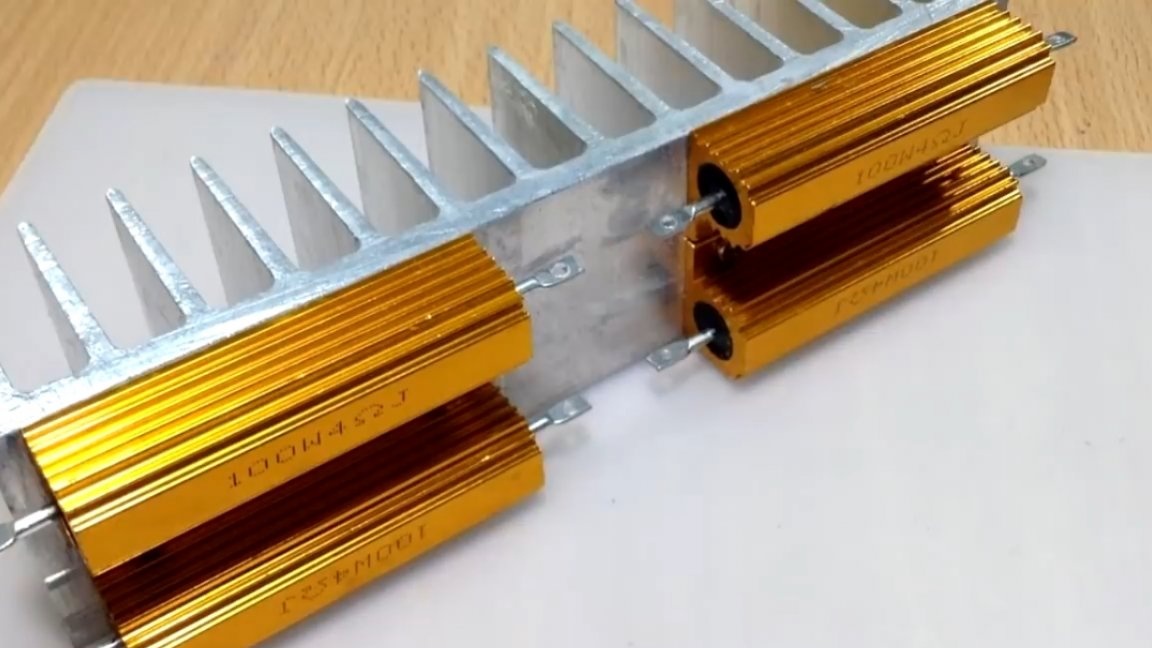
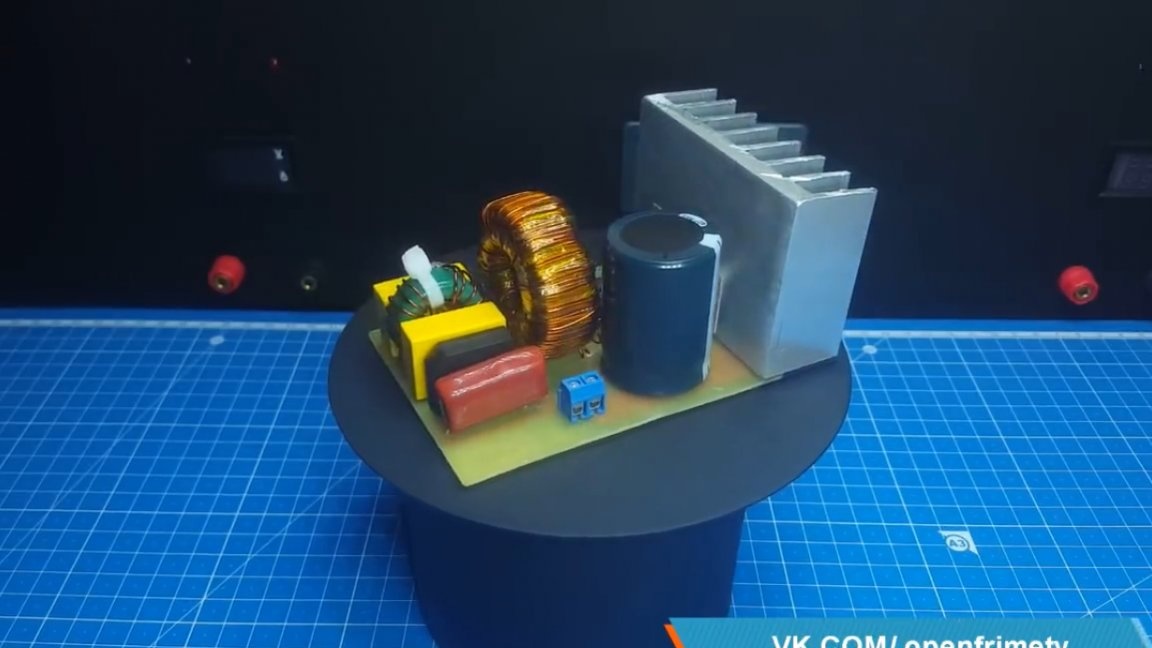
The only thing for the test is that the author replaced the 35n60 transistor with 20n60, since it is cheaper and will not be so offensive if something happens. Such an aluminum profile is used as a radiator:

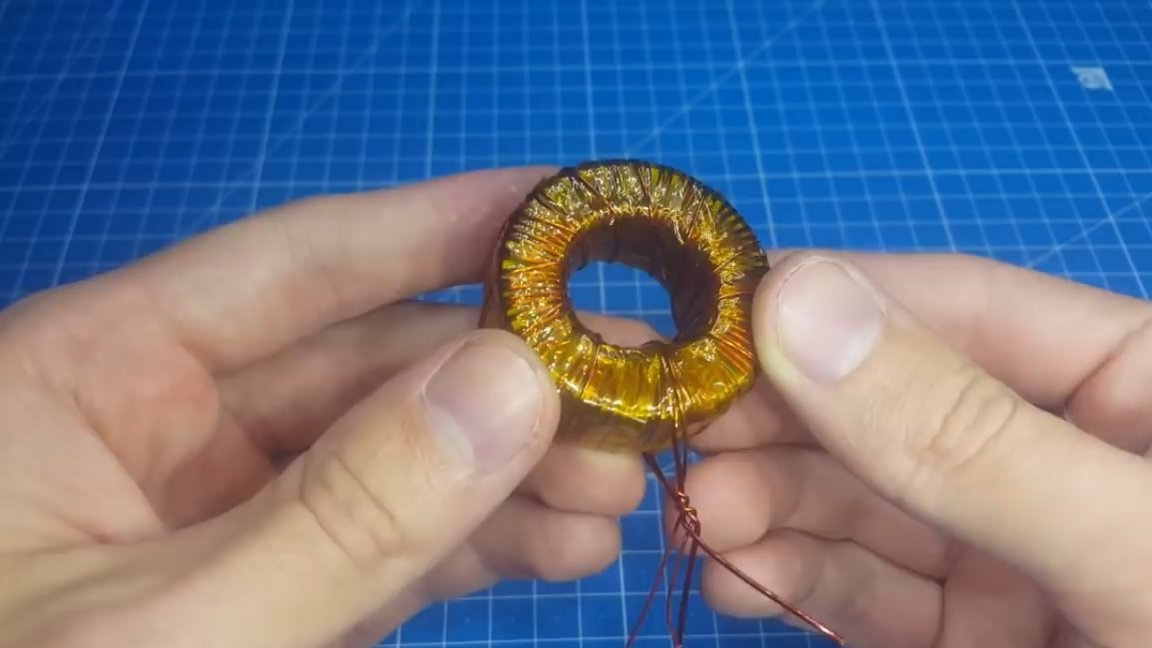
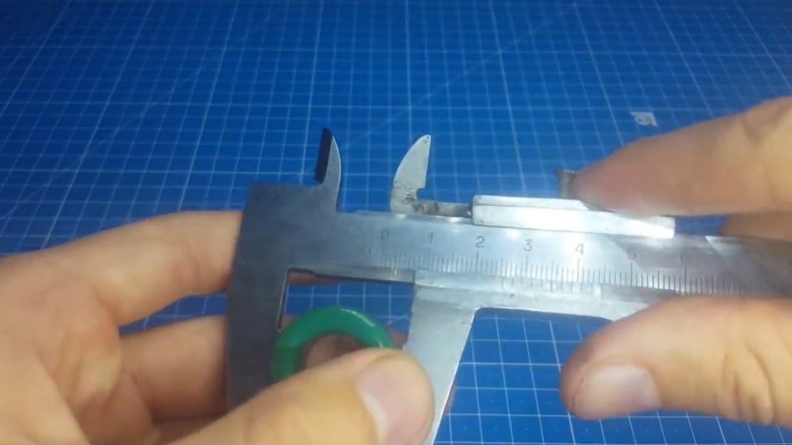
It has large dimensions and can easily cool power elements. Now it's time to make a throttle. This is the hardest part of the circuit. The program will help us in its calculation:

We enter all the necessary data in it and at the output we get the winding parameters. The core in this case will be like this:

It was possible and smaller, but then you have to wind more turns. Also, do not forget to check the box next to the wire selection, the author forgot and therefore the inductor shook 2 times.

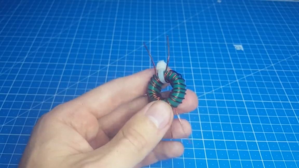
Also, the inductor has a second winding. We make it from a ratio of 7: 1. With 58 turns, the secondary will be 8 turns. The author at 74 turns turned 10 turns. The diameter of the wire here is taken from 0.4 to 0.6 mm. As for phasing, then everything is very simple. The outputs of the inductor, as they are, are installed on the board, the main thing is not to confuse the power and secondary winding. Also on the diagram there is a common-mode choke, we wind it on a ring with a diameter of 20-25 mm and a permeability of 2000. The number of turns is 8-12, the wire diameter is from 0.8 to 1.2 mm.
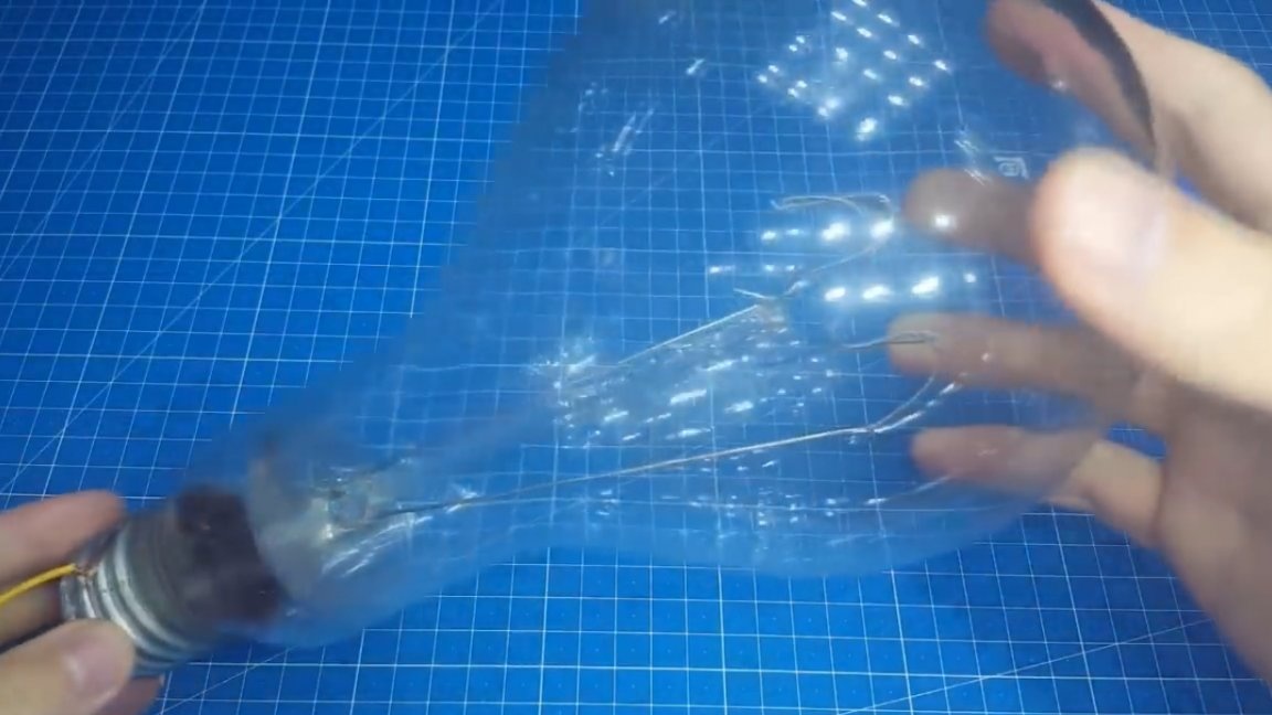
That's all. You can make the first inclusion. Since this is not a pulse unit, it is impossible to put an incandescent lamp in a gap, but the author nevertheless set it, only a kilowatt, I just did not want to go out to the shield in the case of a short circuit and turn on the plugs.
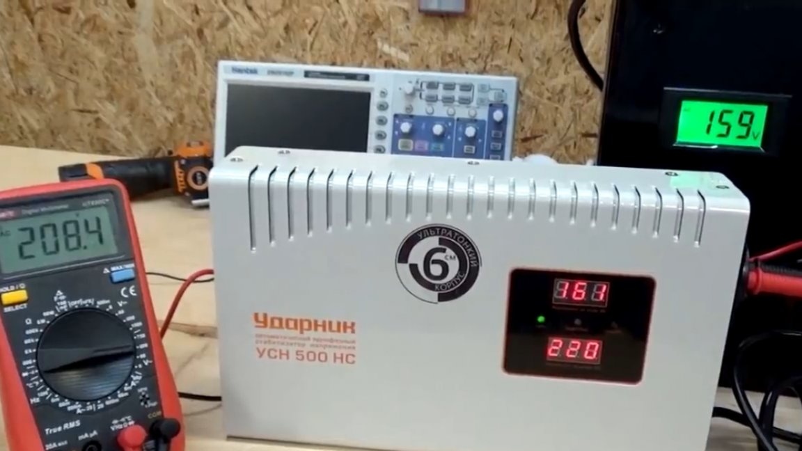
After switching on, the circuit worked. In the load, the author hung 2 incandescent bulbs per 100W connected in series.
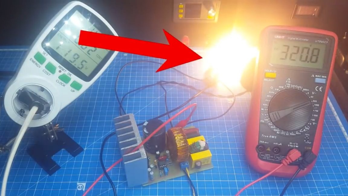
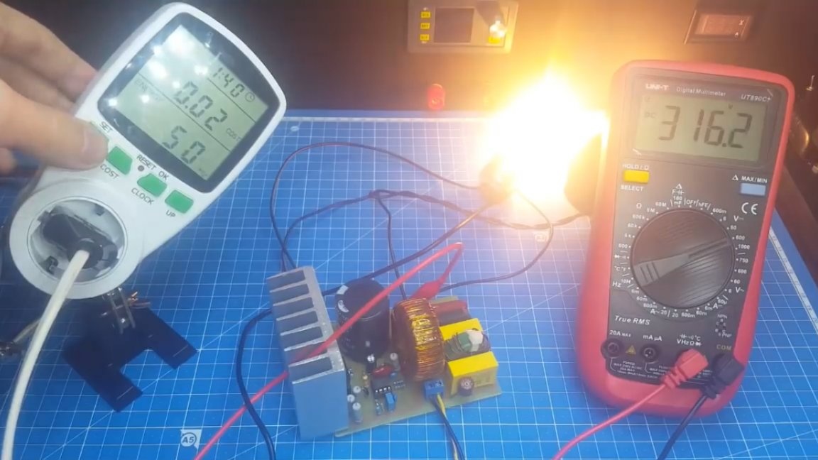
As you can see, with a low input voltage at the output, we get a voltage in the region of 315V.Now you need to see how the circuit with the pulse generator behaves. To do this, take the power supply from the computer and disassemble it. We need to see if there is a varistor in it, if any, to remove, since it is designed for 275V and will work when 310V is applied. Now we will connect this block directly to the network and see what the cosine will be.
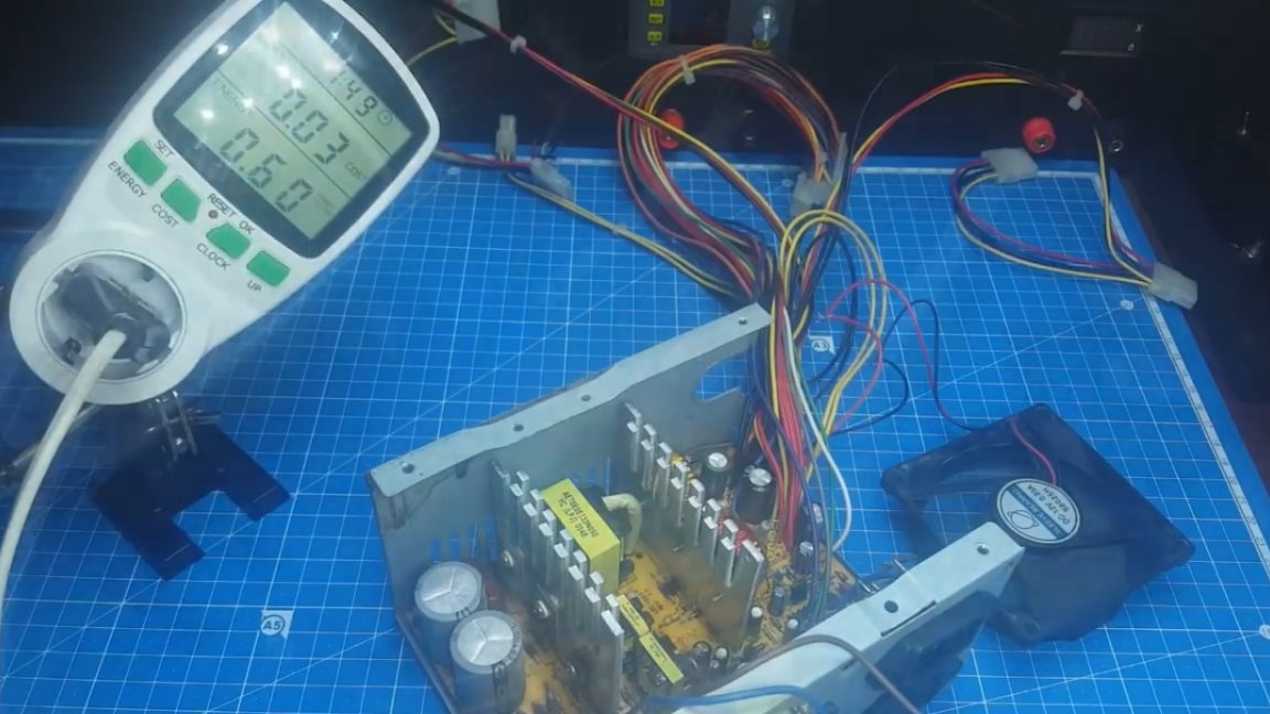
Ok, and now we connect through the corrector. We supply power to the same conclusions where there was a break, so as not to suffer and not to solder the diode bridge. We make inclusion.
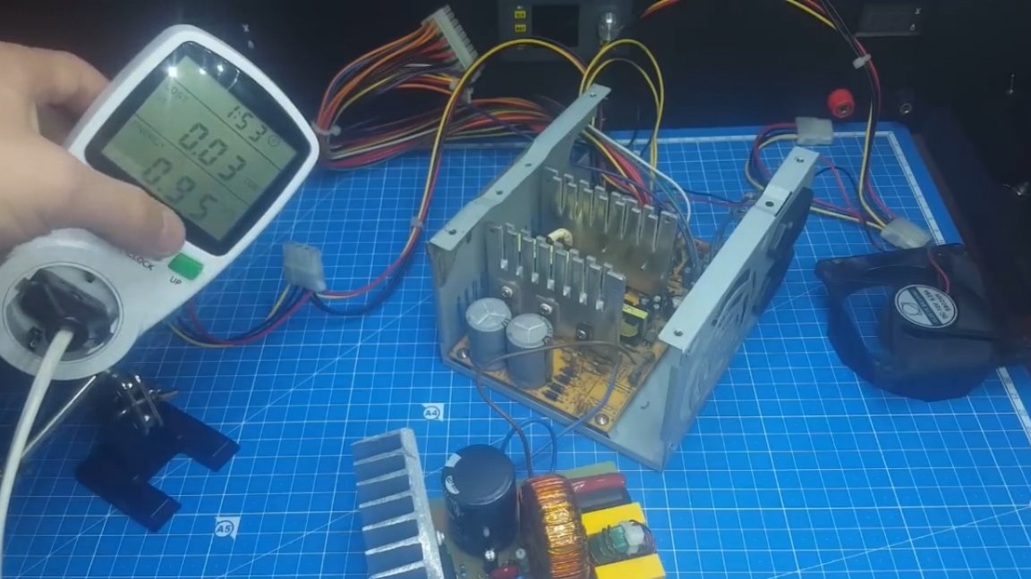
Now we will go through all the readings of the energy meter. Most of all we are interested in cosine f. As you can see, it fluctuates around 95. Well, quite a decent result. Now we’ll put a load on the power supply unit - a nichrome spiral. Power consumption is approximately 160W.
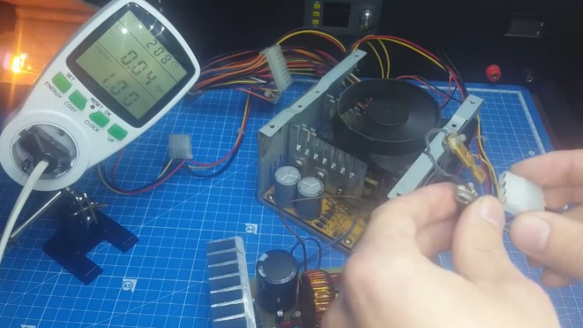
Well, what happens to the cosine? And at this time he begins to strive for unity, but when the load is disconnected, it falls. This is due to the discharge of the capacitor. About the heating. The radiator turned out to be very large and did not heat up for half an hour. But the throttle noticeably warmed up to 65-70 degrees, so it is advisable to install a fan.
Well, that’s all. Thank you for attention. See you soon!
Video: