New Year holidays are approaching. And how to come to the New Year without a gift, to relatives, relatives and friends. And at the same time, the old saying that the best present is a present made has not yet lost its relevance do it yourself. And why not, let's try to make someone an original New Year's gift.
It is proposed to make the simplest Levitron as such a gift. Magnetic levitation always looks impressive and bewitching. Using an invisible electromagnetic force, we lift and hold a small neodymium magnet in the air. Creating a soaring effect by raising and lowering the magnet in a very small range of heights, but with a high frequency. Today you can make such a device yourself. And for this it is not necessary to spend a lot of money and time.
In this article, we consider the scheme and technology for manufacturing magnetic levitron from simple and cheap components.
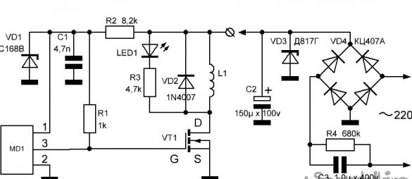
The scheme of the device for magnetic levitation presented below.
The principle of operation of the device
Using this circuit, the coil L1 creates a specific electromagnetic field that holds the permanent magnet on its weight. Since the equilibrium position is extremely unstable, an automatic control and management system is used to hold the magnet in the circuit. The position monitoring sensor is a magnetically controlled sensor MD1, based on the Hall effect. It is located and fixed in the center of the coil, from the side of the working end.
The operation of the Hall sensor (MD1) consists in lowering the output signal (pin 3), up to shutdown, with an increase in static or dynamic magnetic field. With a decrease in the magnetic field, the opposite is true. The Hall sensor operates with a small supply voltage (4 ... 20 V) and low current (3 ... 20 mA), while controlling the power transistor VT1.
LED1 is used for visual control over the operation of the device.
The VD2 diode provides high-speed operation of the coil.
The scheme works as follows.
When you turn on the device, the current passes through the coil L1 and the open transistor VT1.
In this case, the coil creates a magnetic field and begins to attract a permanent magnet. The magnet is attracted to the electromagnet, but rising, it falls into the range of the position sensor (MD1) and switches it with its magnetic field. In this case, a signal is applied to transistor VT1, which turns off the electromagnet. Then the permanent magnet begins to fall, but having left the sensor sensitivity zone, it again turns on the electromagnet. In this case, the magnet is again forced to move to the electromagnet. Thus, the permanent magnet continuously oscillates around a point defined by the system.
In order to prevent the permanent magnet from turning over during oscillations, its position is stabilized, for example, by securing something to it from below. When the magnet flips over, its pole changes, facing the MD1 position sensor and the circuit stops working, since the sensor is controlled only by the south pole of the magnet.
Device manufacturing
1. The basis of the Levitron device is determined by an electromagnet coil. Her choice will largely determine the design of the device.
The coil can be made independently. It is enough to wind 500 ... 600 turns of enameled wire with a diameter of 0.3 ... 0.4 mm onto the tube (about 20 meters of wire will be required). To power such a device, you can use a power supply or charger with a voltage of 5 - 9 volts.
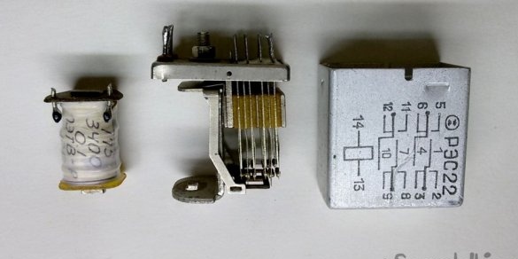
It is possible to use an existing industrial coil. At the same time, it is desirable to know its rated supply voltage and to select an appropriate power source in the future.
In our case, for an original gift, a compact design of the device is required, so a small-sized relay coil was chosen.
2. In addition to the coil, we need a field effect transistor, for example, IRFZ44N or another similar MOSFET, again, depending on the parameters of the used coil. In our case, the IRF630 transistor is used, which remained on a piece of the board after the disposal of video equipment.
You also need a Hall sensor, for example, type A3144, AH443 or another, working in similar modes. In this case, the cheap sensor found in the store, model HAL 508 UA-A-2-B-1-00, was used.
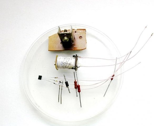
We will understaff the device with the rest of the purchased radio components according to the above diagram.
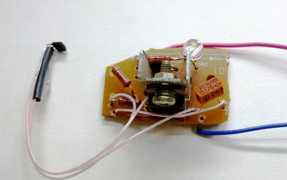
3. To check and adjust the operation of the Levitron, we assemble the left part of the above circuit, with the exception of the resistor R2 and with a change in the nominal value of R3 to 330 Ohms. The right side of the circuit is the power source of the device, and in this version it is not needed. It is more convenient to assemble and test the circuit on a universal circuit board, but since the existing transistor was already soldered together with the heatsink on a piece of the circuit board of a suitable size, I soldered the circuit next to it.
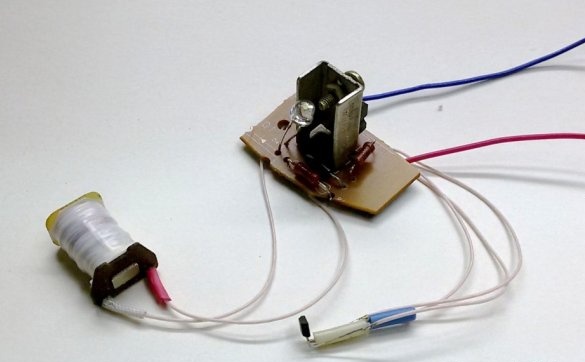
4. Assemble the coil. We place the Hall sensor and temporarily fix it in the center of the hole, at the very bottom of the coil.
5. Testing the device. We fix the coil at a certain distance from the surface of the table. After that, the magnetic levitation device can be powered. Since the coil of the previously mentioned relay has a winding resistance of 210 Ohms and is designed for DC voltage of 12V, we connect it to the appropriate power source.
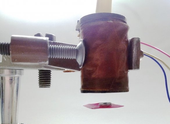
Then it is necessary to determine which side to orient the permanent neodymium magnet to the electromagnet. We turn on the levitron (the LED should light up) and bring the magnet to the bottom of the coil, from the side of the Hall sensor. If the magnet is attracted to the coil and the LED goes out, the magnet is oriented correctly, but if the magnetic field of the coil pushes it out, then the magnet must be turned over. If the LED does not go out, when connecting the magnet to either side, it is necessary to interchange the ends of the coil, i.e. change her poles. When done correctly, the electromagnetic force will pick up the magnet and keep it in the air. Do not forget to stabilize the position of the magnet so that it does not roll over during oscillations. In this case, a neodymium ring magnet with a diameter of 7 mm and a thickness of 1 mm, taken from a micro earphone, was used. To stabilize it, a piece of insulating tape glued on one side of the magnet is enough.
Note. The first tests with this coil were not successful. The core of the relay coil amplified the magnetic field, but also exerted its influence when the coil was turned off. During setup, the position of the magnet was not stable or the magnet was attracted to the core with the coil turned off. When the core was removed from the coil, the process stabilized, as can be seen in the photo.
6. Upgrade the device. Further tests revealed some flaws. Firstly, the need for an additional power source, which increases the complexity and size and does not add originality to the gift. Secondly, with increasing flight range (distance from the coil), you need to increase the supply voltage, and this leads to undesirable heating of the coil.
It is possible, of course, to dwell on this option, using the opportunities obtained. It remains only to "pack" the device in a decent case.
7. You can make the second version of the device by replacing the coil with a higher voltage (but with a lower current consumption) and make an additional built-in transformerless power supply. A complete diagram of this device is given at the beginning of the article.
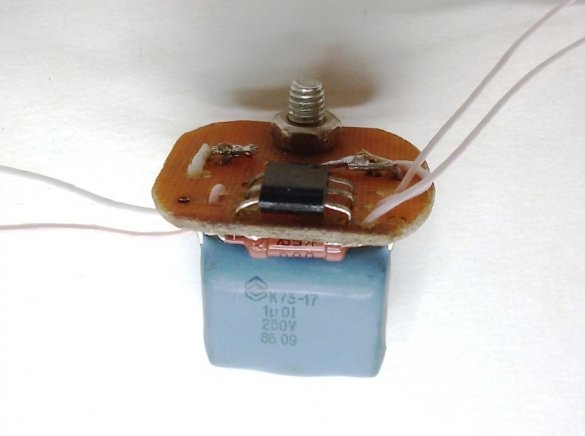
The second version of the coil from an imported relay is designed for a voltage of 110 volts and has a winding resistance of 4700 Ohms. We complete the device with parts according to the scheme.
8. We produce a transformerless power supply (right side of the circuit). It converts an alternating current of 220 volts to the voltage we need - about 100 volts (determined by the Zener diode VD3) of a small direct current (determined by the capacitance of a capacitor C3 of type K73-17). Such a PSU has advantages - a simple circuit and small dimensions. But it also has a drawback - there is a danger of electric shock when it comes into contact with parts on the switched on device. However, subject to safety regulations, the absence of galvanic isolation in a fully insulated device will be safe.
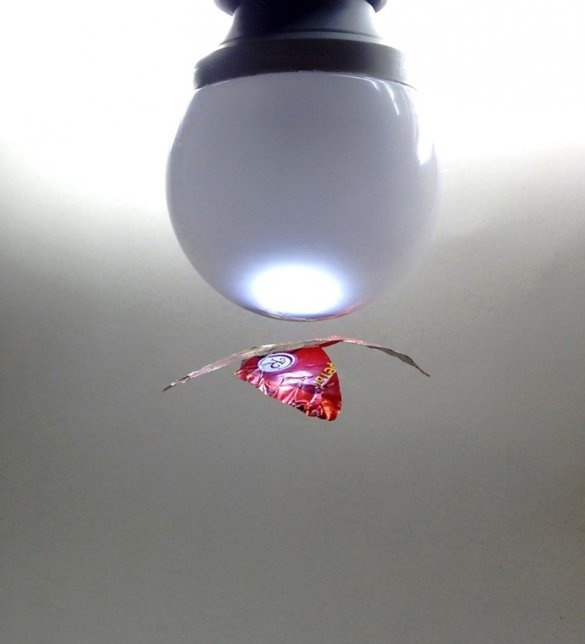
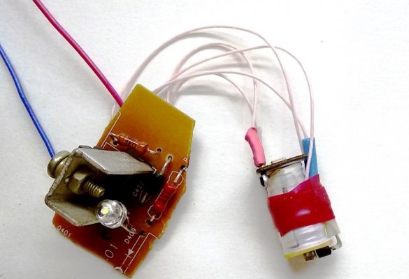
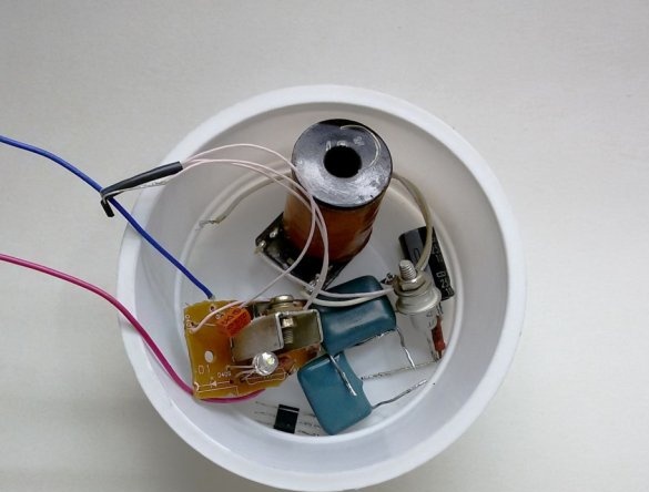
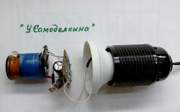
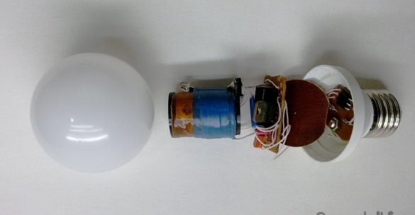
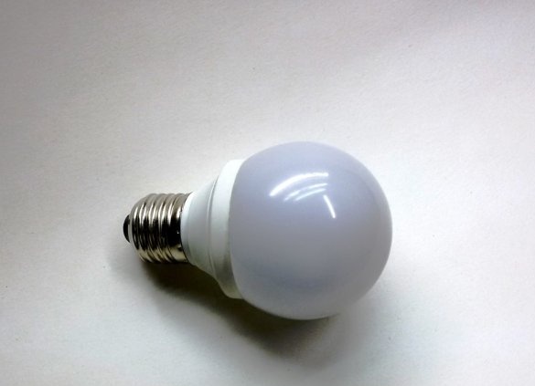
9. As the case for the Levitron, we use mating in size, a cartridge from a burnt-out fluorescent energy-saving lamp and a light-diffusing cover from an LED lamp. We place and form a circuit on the board according to the internal dimensions of the cartridge, solder the board to the terminals of the cartridge.
Since the smoothing capacitor C2 is not included in the cartridge, install it on the Levitron board. We also remove the radiator of the transistor, since with a low load power it is optional.
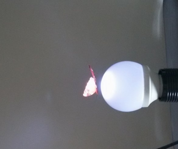
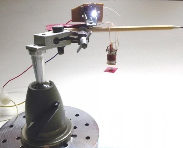
10. Assemble the device on the stand and test.
In this case, a ring neodymium magnet with a diameter of 10 mm and a thickness of 3 mm was used. Set the MD1 sensor in the center of the coil and fix it with a piece of foam. By moving the Hall sensor, we achieve a stable hovering of the magnet at the maximum distance from the coil. We fix the position of the sensor relative to the coil.
11. After setting up the Levitron, we assemble and glue the device. To give the device a greater effect of an LED lamp, you can add 2-3 permanently on LEDs with limiting resistors inside the lampshade. To ensure heat dissipation, provide ventilation holes in the cartridge, if they were not provided for by the design of the former lamp.
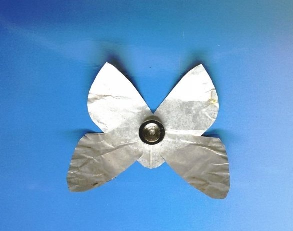
To create a wrapping soaring effect, the magnet can be veiled with some kind of light figure, for example, the outline of a moth.