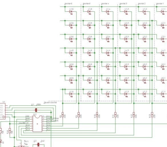
Charliplexing is a way to connect a large number of LEDs to a small number of microcontroller pins. The method got its name from the name of its inventor Charlie Allen. The microcontroller is not suitable for this, but only one in which the outputs can be programmatically translated into a high impedance state. And the LEDs wear out a little faster, because despite the low average current, the pulse is extra large. But the possibility of using low-output microcontrollers often becomes the determining criterion in favor of charliplexing.
The author of Instructables under the nickname fulda came up with how to apply charliplexing in a small desktop tree. Its LEDs are connected in a 6x7 matrix and are controlled by a PIC16F15323 microcontroller. So 13 conclusions would be required for this, and with charliplexing - only 7. Not only enough, but extra ones remained. The master connected a large LED to one of them, the brightness of which changes smoothly.
, the inscriptions are readable.
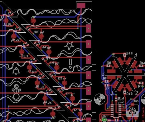
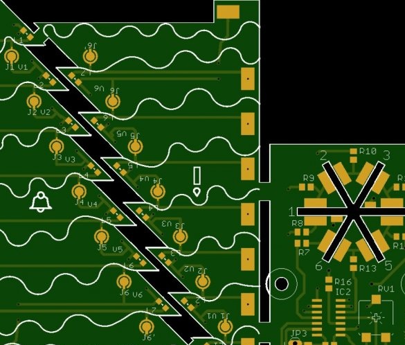
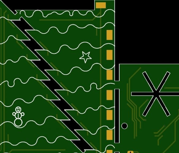
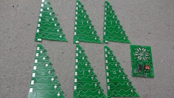
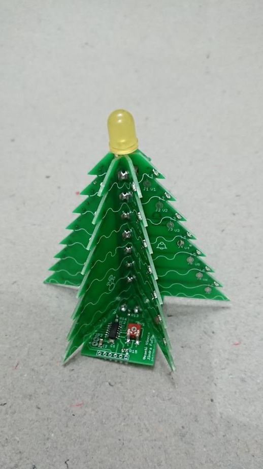
The Christmas tree is assembled on six identical double-sided boards with LEDs and one lower base-stand, also double-sided, with a microcontroller and other parts.
in normal resolution.
At first, the master collects both boards, then in the stand board he makes slots for the Christmas tree boards. Puts them there and solders their contact pads to the contact pads of the Christmas tree boards. Then, the adjacent pads adjacent to each other are soldered to them, and now everything is firmly held and correctly electrically connected.
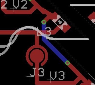
On two of the six vertical boards below, in addition to large pads, there are also small ones. And on the baseboard, they are located next to the slots for the corresponding boards. They are intended for the LED on the top of the tree. From these sites, printed conductors go up and end there with sites for this LED. Solder it, observing the polarity (which, incidentally, also applies to small SMD LEDs), it is necessary to these two boards. There are also places for jumpers and for drilling on vertical boards.What is the number of the board, it is necessary to solder the jumper to such platforms, and drill a hole in the same place, like this:
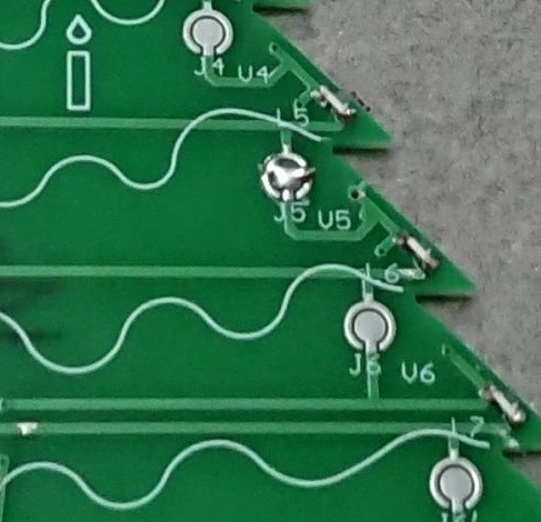
The sixth board has not one, but two jumpers.
To order boards, fulda generated a Gerber file, which it placed in. When placing an order, it is important to indicate how many boards you need to make, as well as a thickness of 1.6 mm.
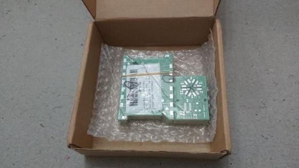
When the finished boards arrived, the master first divided them. Those boards that have additional conductors, for convenience, are marked with drawings with a snowman and a bell.
So everything looks in assembled form:
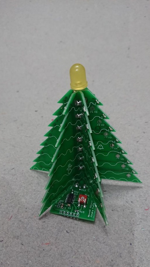
You can order another lower board, do not solder anything there, but make a slot. It will hold the vertical boards during assembly, it is not necessary to solder it, just put it on. And after soldering all the boards to each other, but before installing the large LED - remove it.
The program for interrupting from the timer goes through all the LEDs and includes or does not turn on each of them, depending on the status of the corresponding bits in the RAM area allocated for frame storage. Periodically, it writes the next frame to this area, and how often it depends on the number at the ADC output where the variable resistor is connected. Also, the program smoothly changes the brightness of the upper LED.
Using the links you can download archives from and.
To fill in the firmware, the board provides platforms for connecting a serial programmer.
The master connected the 3hAA battery compartment in the correct polarity to the board and screwed it with M3 bolts with the corresponding nuts:
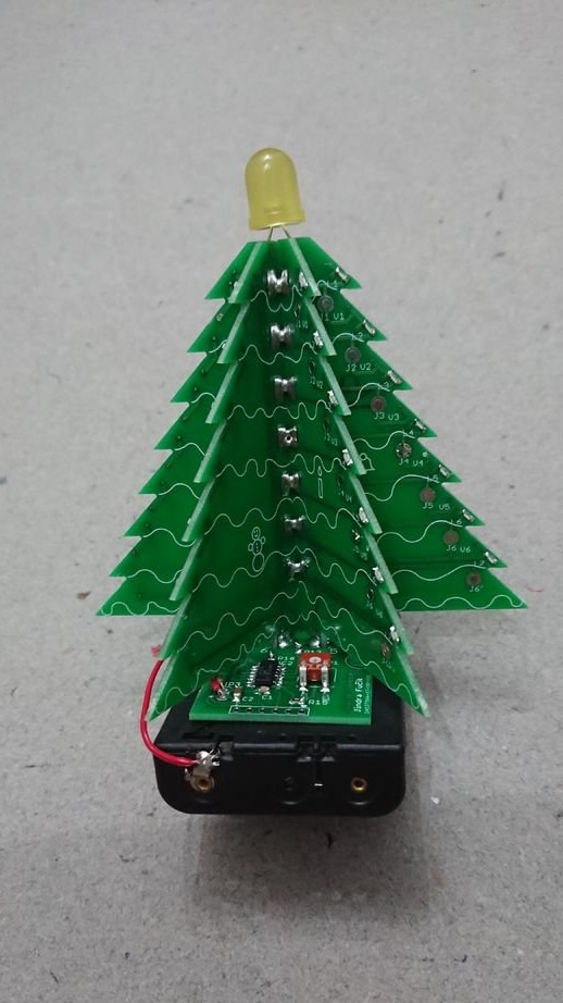
I filled the compartment with elements, and everything started from a half-turn:
Repeat everything correctly, and you will do the same.

