
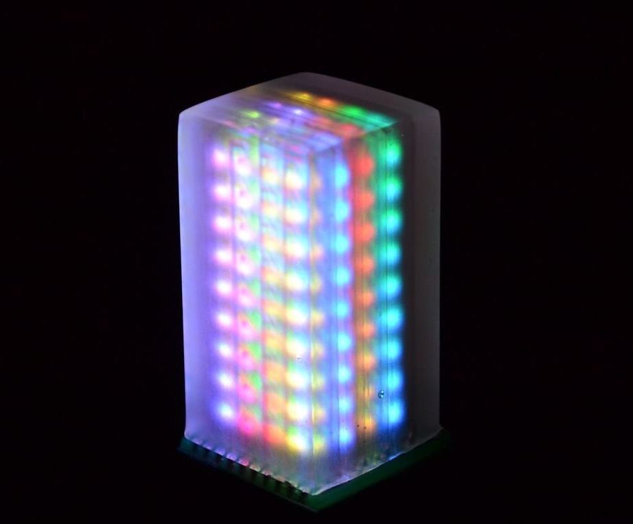
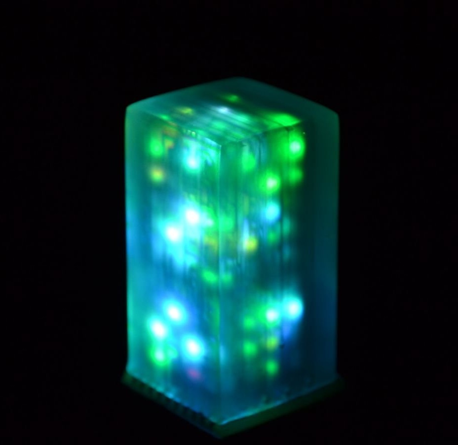
This project uses SMD LEDs attached to glass printed circuit boards. The LEDs turn off and light up, simulating the movement of sand, according to the position of the 3D cube in space.
Below, a video 3D cube in action.
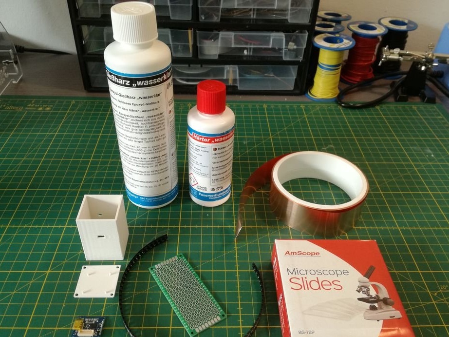
The following list includes the materials needed to build a cube:
144 pcs SK6805-2427 LEDs ( )
Housing
Additional materials and tools required for the project
Hair Dryer
regular thin tip soldering iron
3D printer
laser printer
thin wire
PCB pins
low temperature solder paste
ferric chloride
regular glue (e.g. UHU Hart)
silicone sealant
photo paper
acetone
Transparent PCB manufacturing
The obvious problem with printed circuit boards is that they are not transparent. The following describes in detail how to make transparent printed circuit boards.
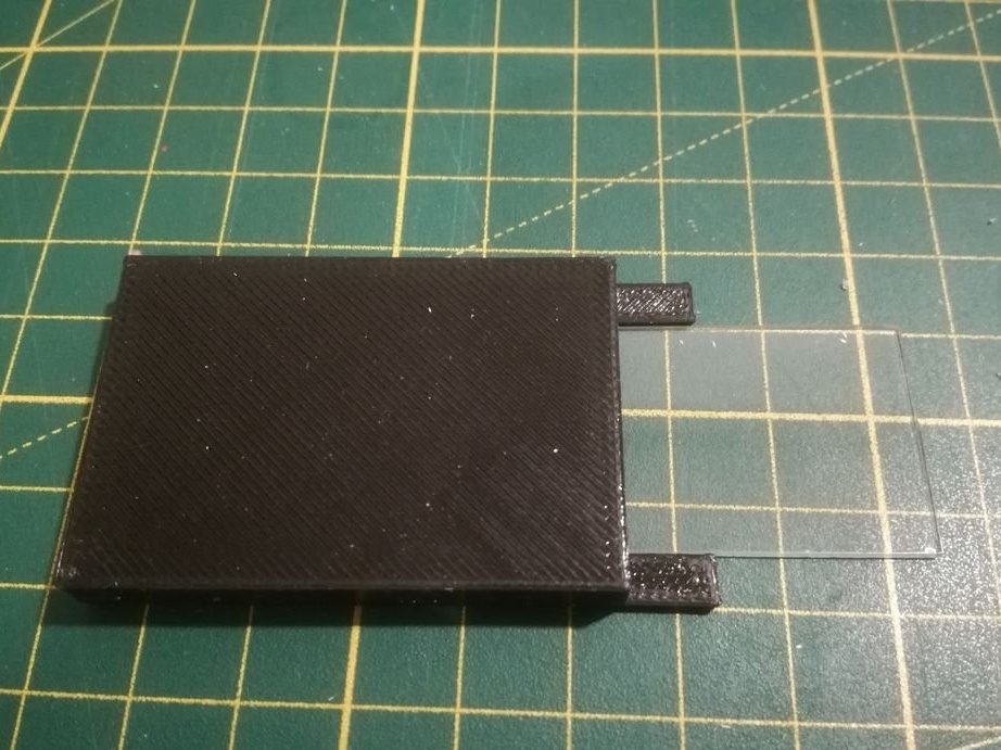
First you must cut the microscope slides into square pieces using a 50.8 mm glass cutter.
Watch this video to understand how to do it.
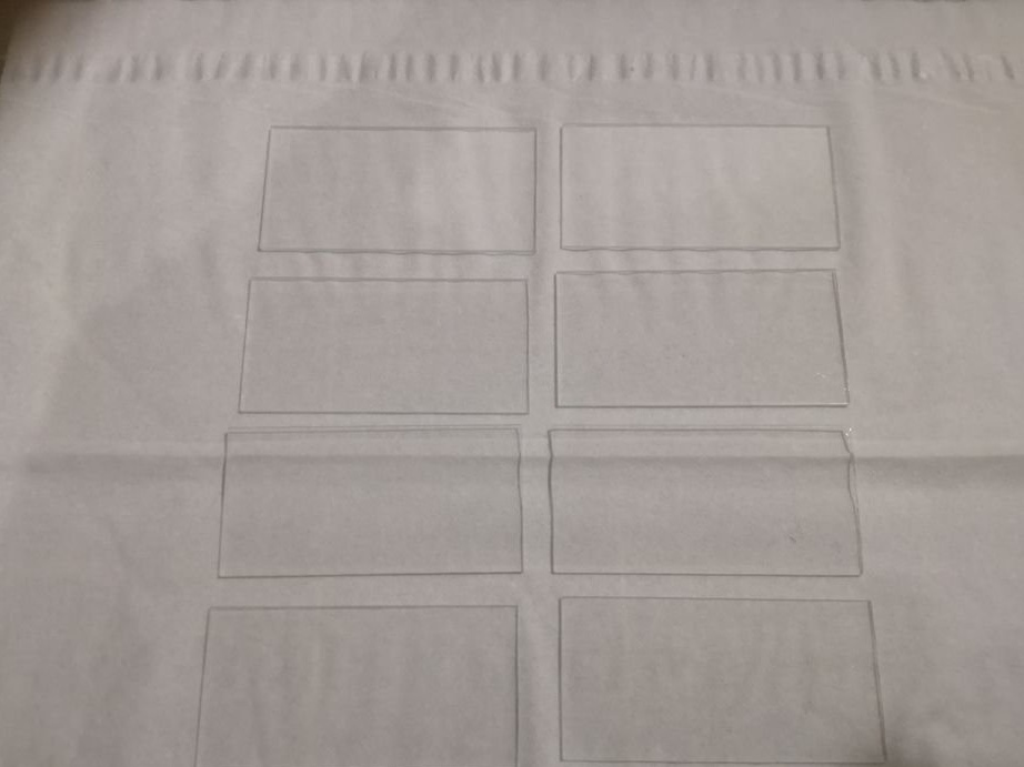
The attached .stl file has model template, in order to make it easier to measure the desired length. You will need 4 glasses, but it is better to do with a margin of 6 - 8 pieces
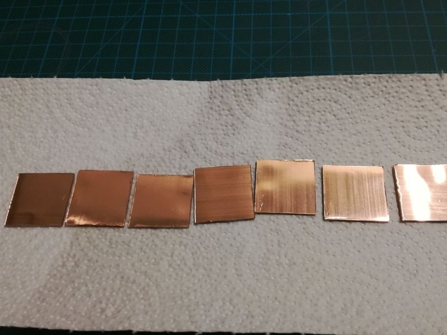
After that, cut the copper tape into pieces that are slightly larger than the cut glass substrates.
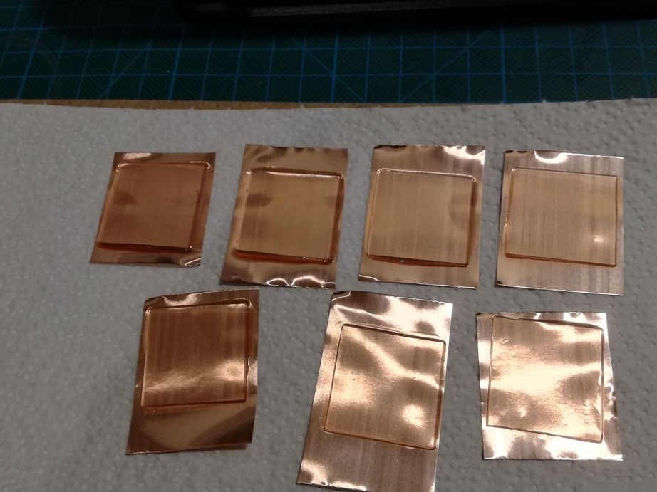
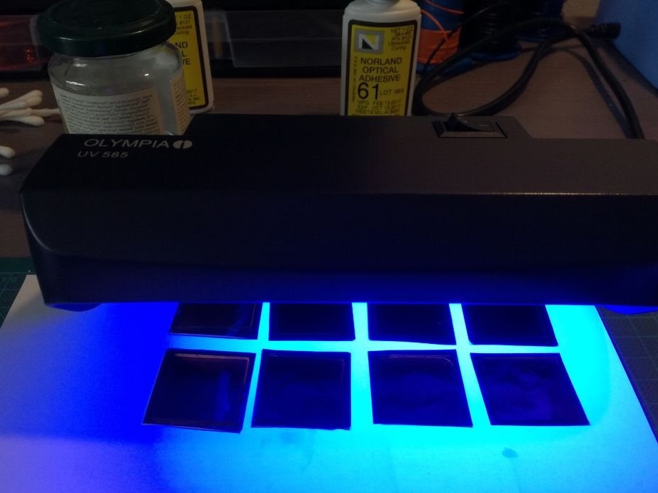
Clean the backing and copper foil with alcohol or acetone, and then glue them together. Make sure there are no air bubbles inside. Use Norland NO81, which is a quick UV glue recommended for bonding metal to glass. Sand one side of the copper foil with sandpaper to make it rougher. To cure the adhesive, you can use a UV lamp to check banknotes.
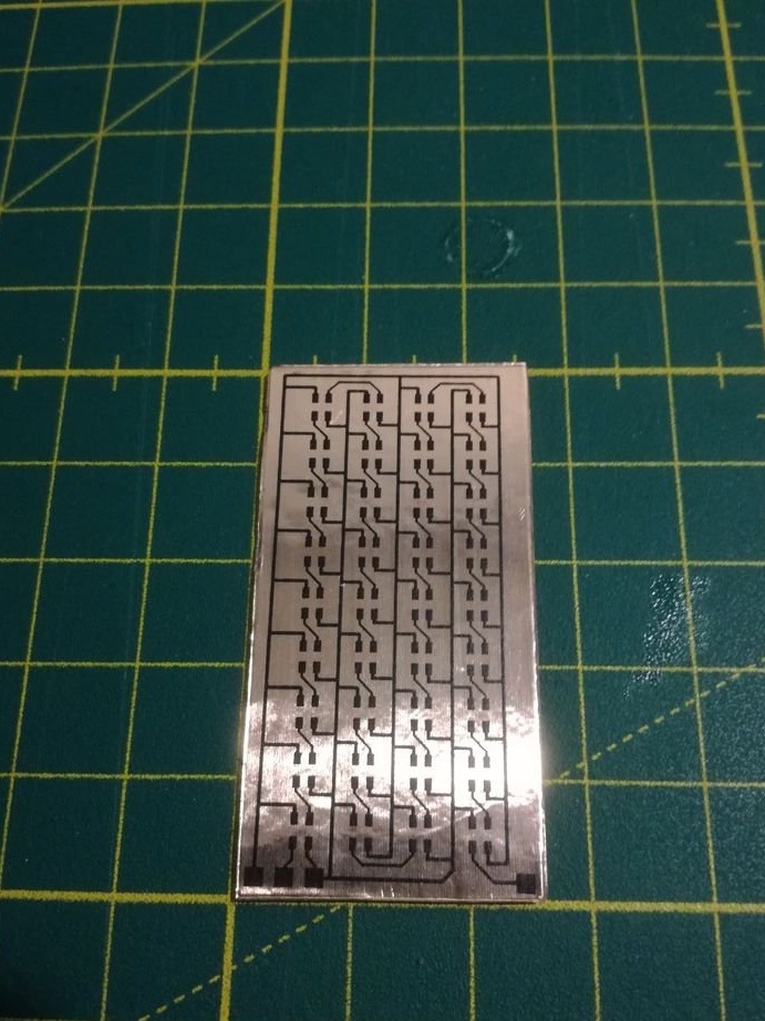
After the adhesive has set, cut the foil along the edge of the glass substrate.
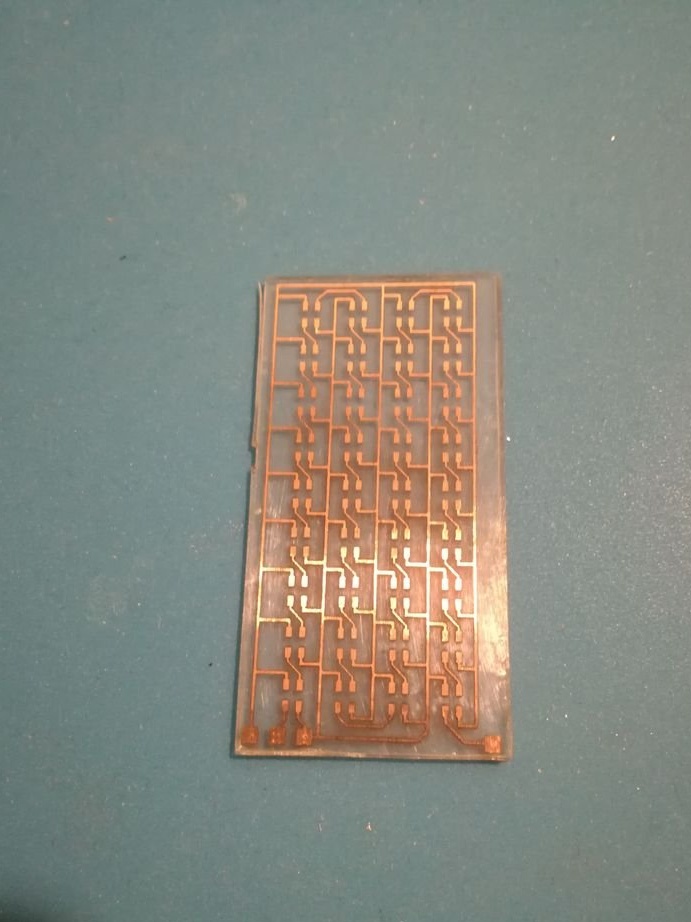
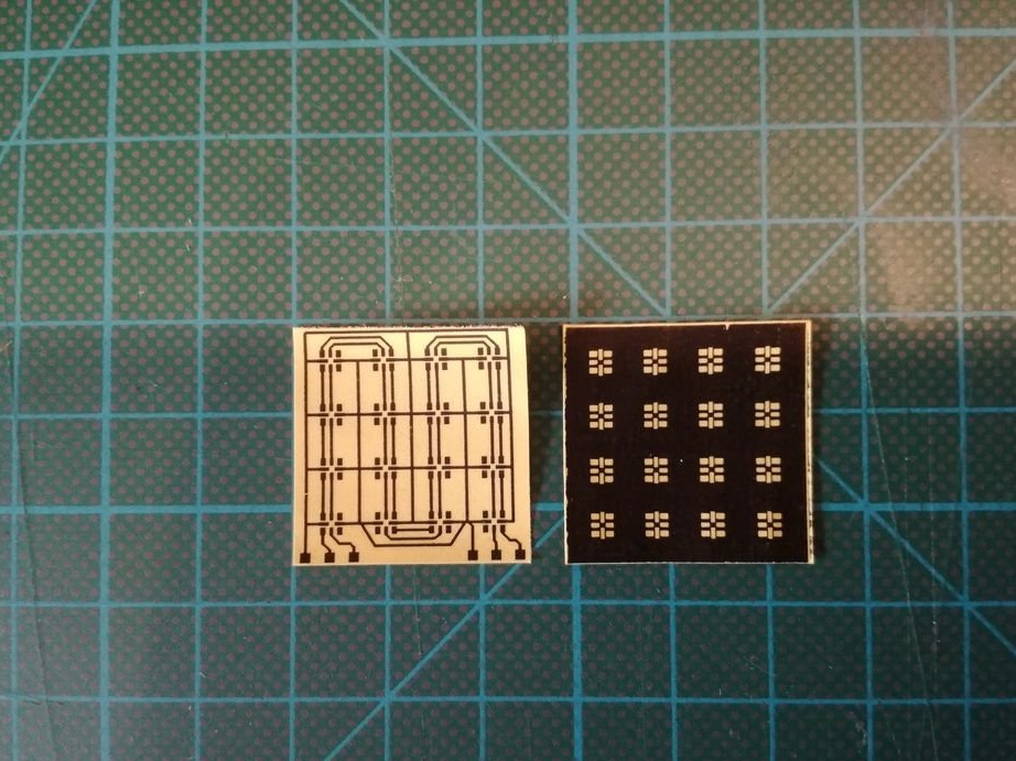
The photo shows a printed circuit board and a stencil for solder paste from one author's project.
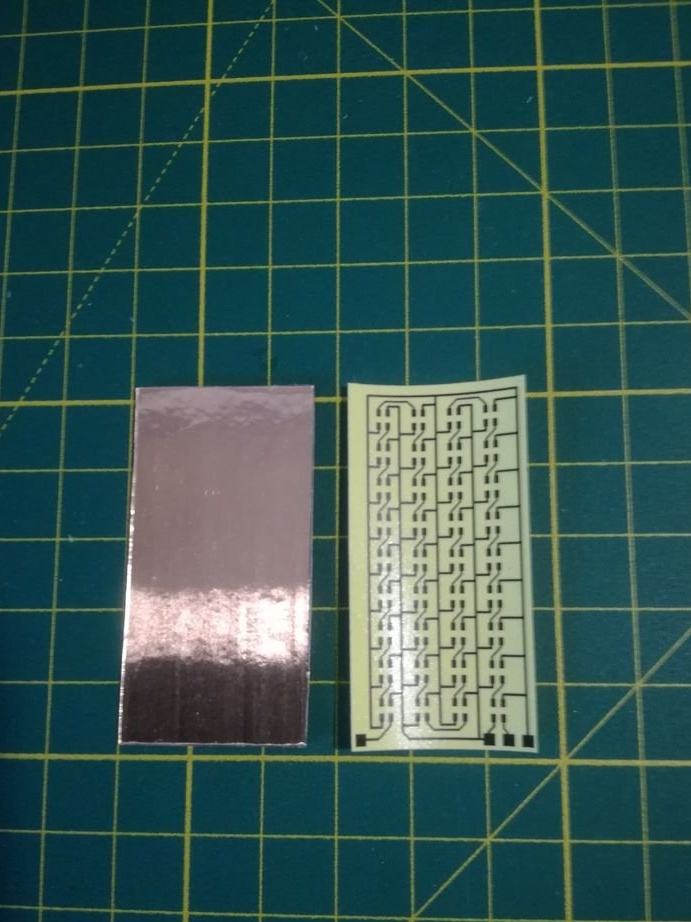
Transfer the printed circuit board design from photo paper to copper in any way convenient for you. You can use LUT or the method that I described here.
Next, etch the copper. (It is possible with ferric chloride. I use a mixture of peroxide, lemon and ordinary salt).
Remove Toner Using Acetone
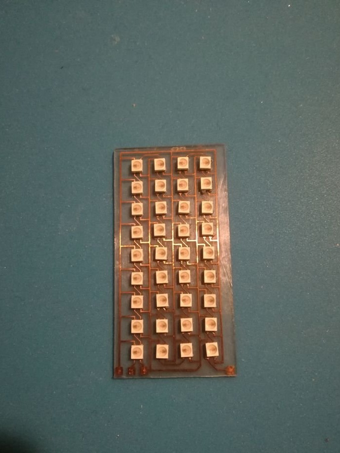
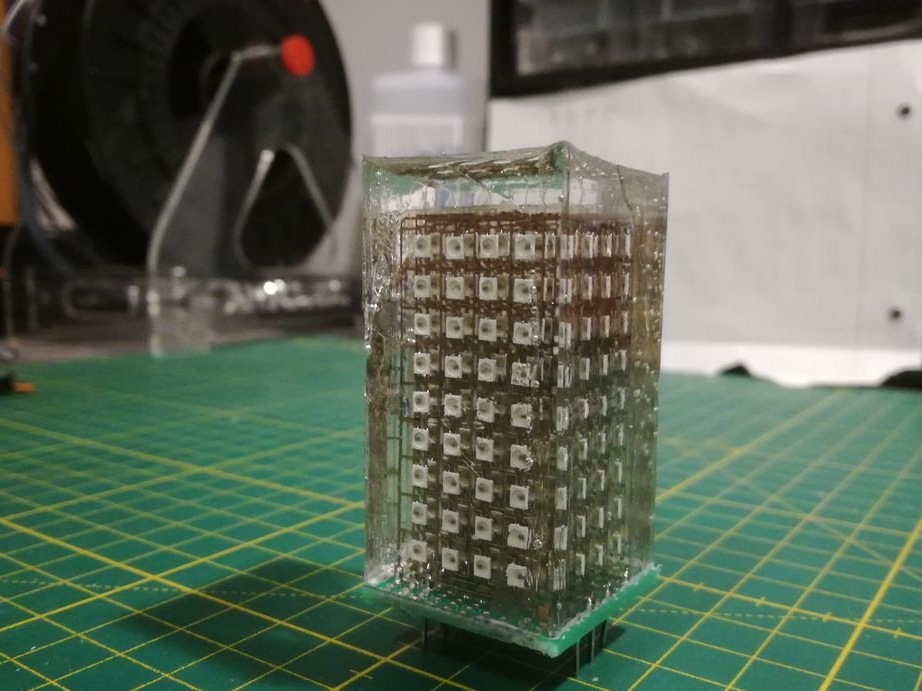
The author uses large LEDs SK6805-2427, which greatly facilitates their soldering.
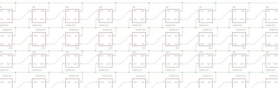
Cover all contact pads with low-temperature solder, and then install the LEDs on top, remembering to observe the correct orientation of the LEDs, referring to the attached diagram.
To solder the installed LEDs, the author put the circuit boards in the oven and heated them until the solder melted. True, I still had to use a hairdryer later, since not all LEDs soldered well.
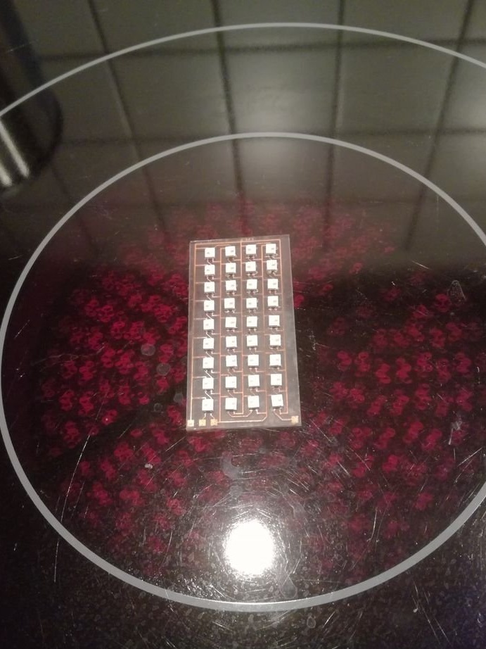
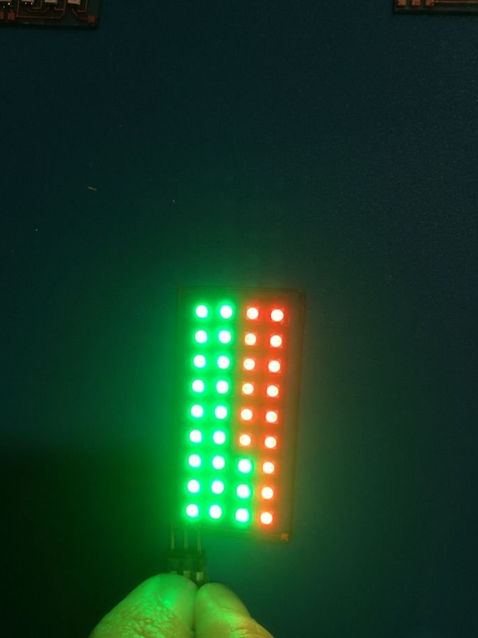
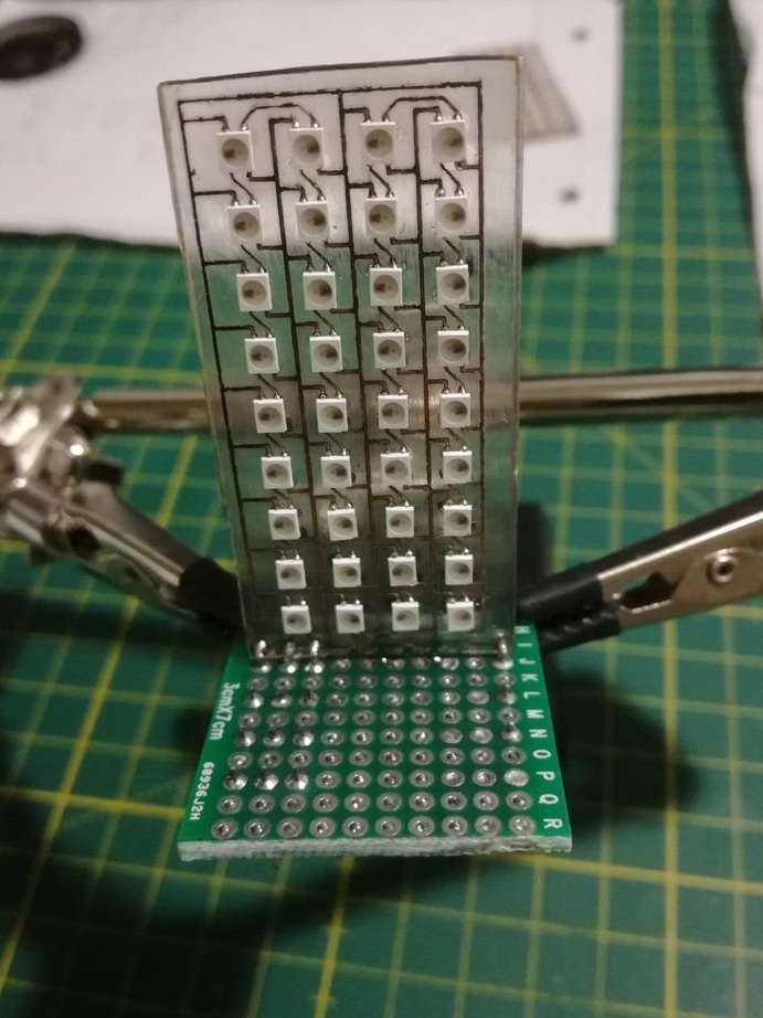
To test the LED matrix, you can use Arduino Nano to load the sketch into Strandtest Adafruit NeoPixel and connect it to the matrix using the Dupont connector.
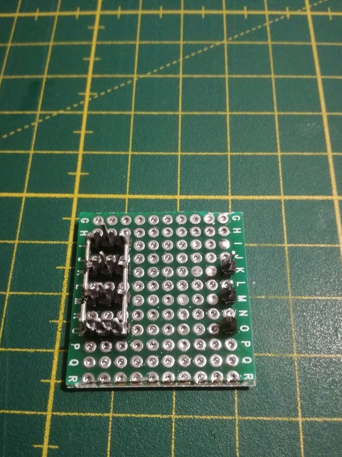
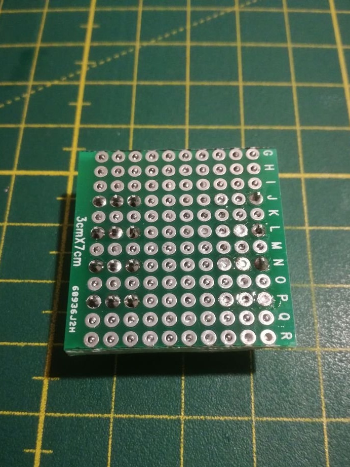
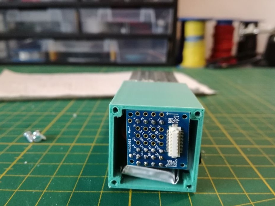
For the bottom printed circuit board, you will need a piece of a breadboard printed circuit board measuring 30x30 mm. Then solder to it several pin tips, where after that the glass printed circuit boards will be attached. The VCC and GND pins were connected using a small piece of tinned copper wire. Then close all remaining through holes with solder, because otherwise the epoxy may leak during pouring.
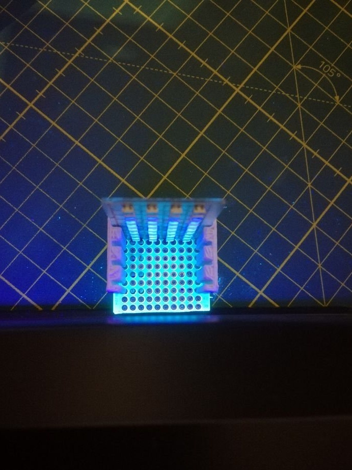
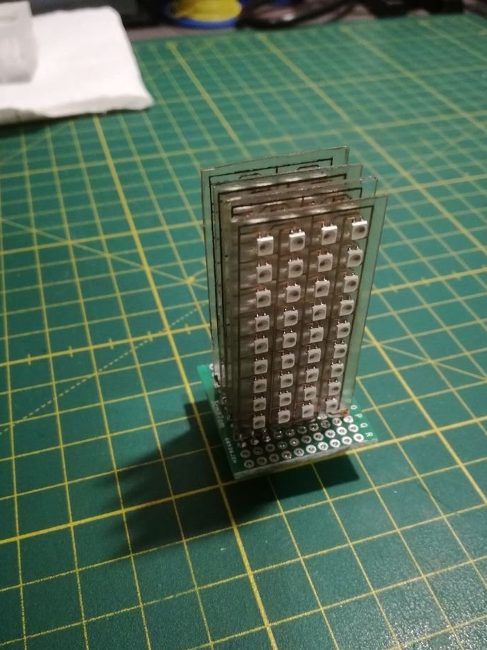
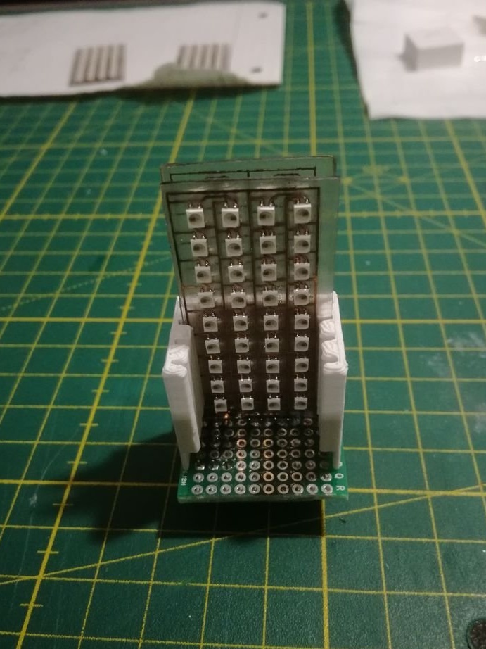
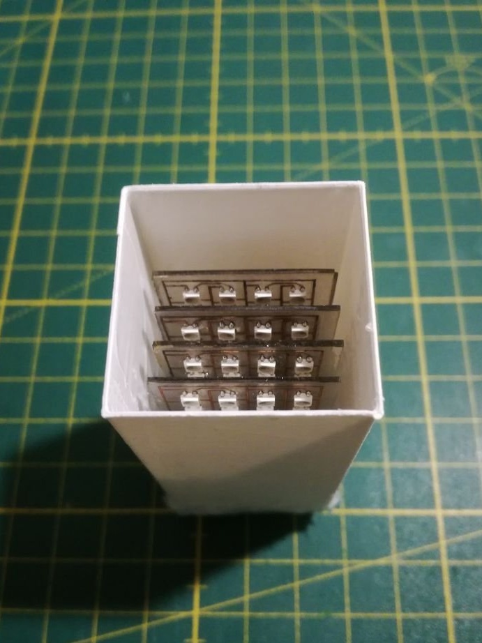
To attach the LED matrix to the bottom PCB, use UV glue, but with a higher viscosity (NO68). For proper alignment of printed circuit boards, use a special template (see the Attached .stl file). After gluing to the base, the glass circuit boards swayed a bit, but became tougher after they were soldered to the findings on the breadboard. To do this, just use your regular soldering iron and regular solder. Again, it’s nice to check each matrix after soldering. The connections between the Din and Dout of the individual matrices were made using Dupont connectors connected to the pins on the bottom of the breadboard.
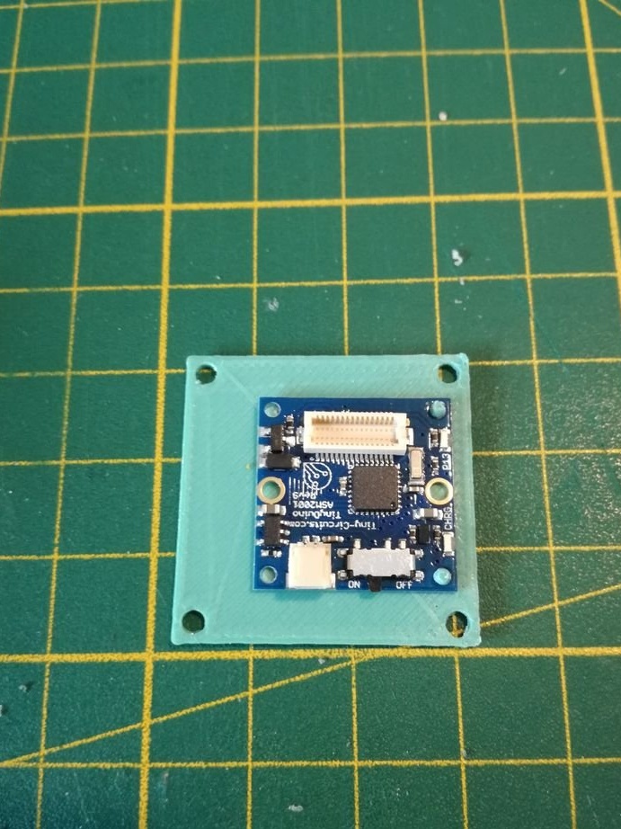
Since it is necessary to make the case size as small as possible, TinyDuino is used. is an Arduino-compatible board in an ultra-compact package. Imagine being able to get the full power of an Arduino Uno in 1/4 size! The basic kit, which includes a processor board, with a USB connector for programming, a proto-board for external connections, as well as a small LiPo battery. The author was also going to buy a 3-axis accelerometer, which is offered for use with TinyDuino, instead of the GY-521 module that he used in this project. This would make the circuit even more compact and reduce the required dimensions of the case. The diagram of this assembly is quite simple and is given below.
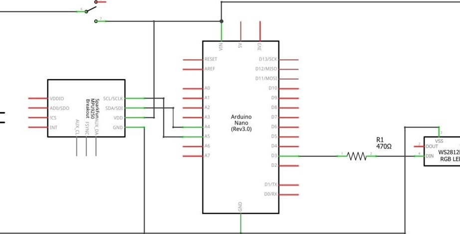
Some changes were made to the TinyDuino processor board, where an external switch was added after the battery. There is already a switch on the processor board, it was just short to fit into the case. Connections to the breadboard and the GY-521 module are made using pin lugs that do not allow the most compact design, but provide greater flexibility than direct soldering of wires. The length of the wires / contacts at the bottom of the breadboard should be as short as possible, otherwise you can no longer connect it to the top of the processor board.
After you collected electronics, you can download the attached code and verify that everything works. The code includes the following animations that you can repeat by shaking the accelerometer.
Rainbow: Rainbow animation from the library Fastled
Digital Sand: This is an extension Adafruits animated led sand in three dimensions. LED pixels will move according to the values read from the accelerometer.
Rain: pixels fall from top to bottom depending on the slope measured by the accelerometer
Confetti: random colored spots that blink and fade out of the library Fastled
Assembly
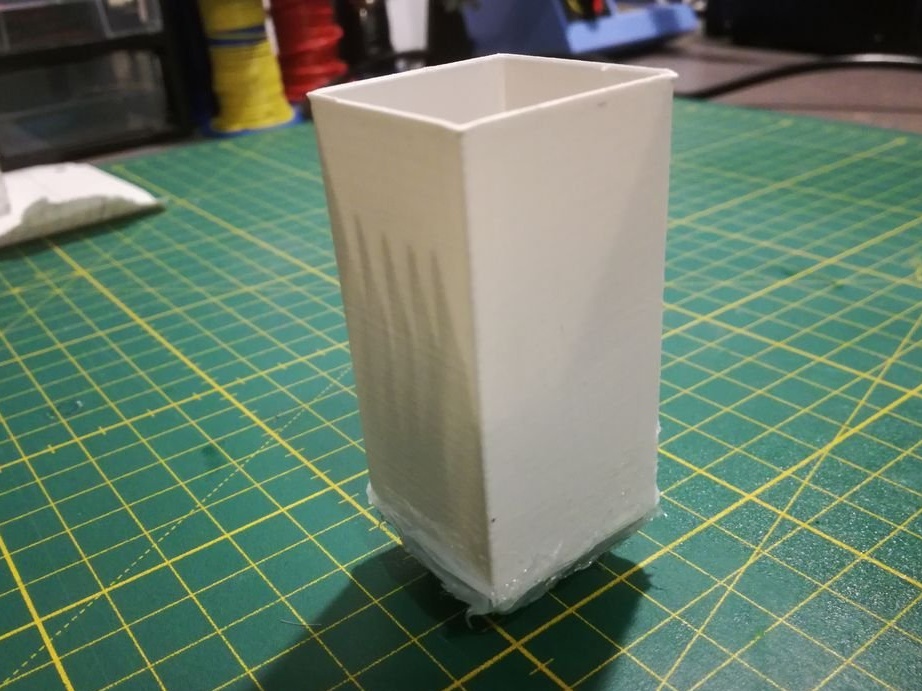
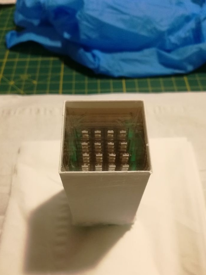
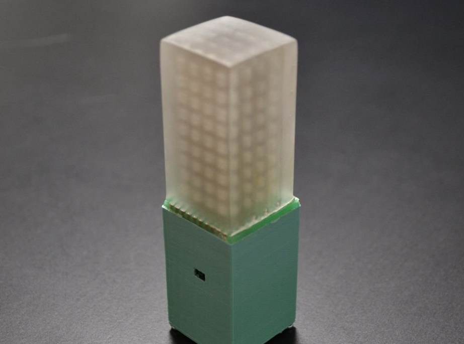
It was important to find a suitable material that could be used as a mold. After some unsuccessful trial tests, the author found that the best way is to print a three-dimensional shape and then cover with silicone sealant. Print one layer from a 30 x 30 x 60 mm box using the “spiralize outer contour" parameter in the Cura file (.stl file). Then cover it with a thin layer of silicone inside, which will make it very easy to remove the mold after pouring. The mold was attached to the bottom circuit board also using silicone sealant.Make sure there are no holes so that the resin cannot leak out and voids do not form.
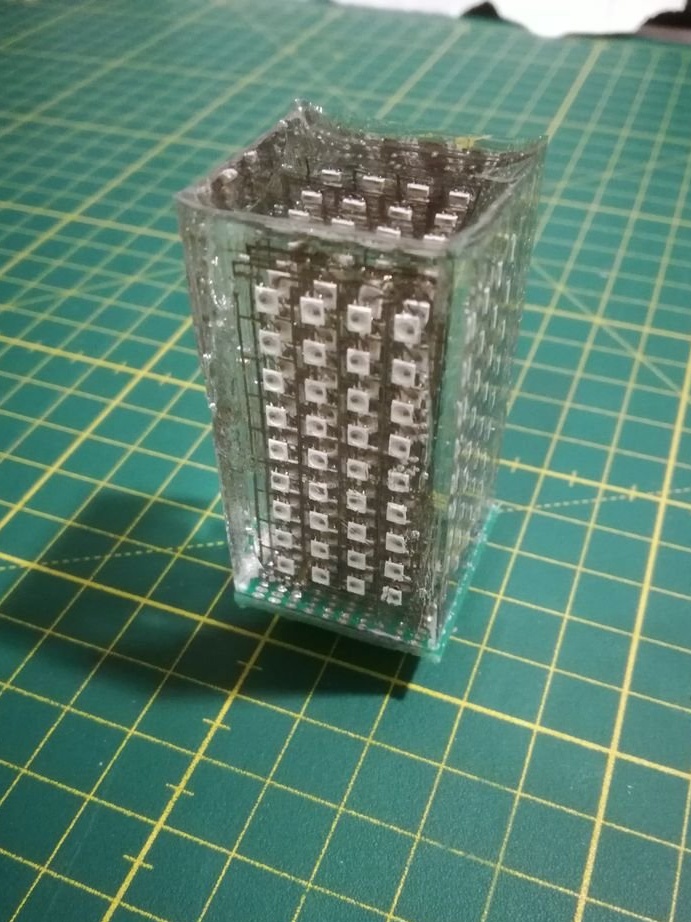
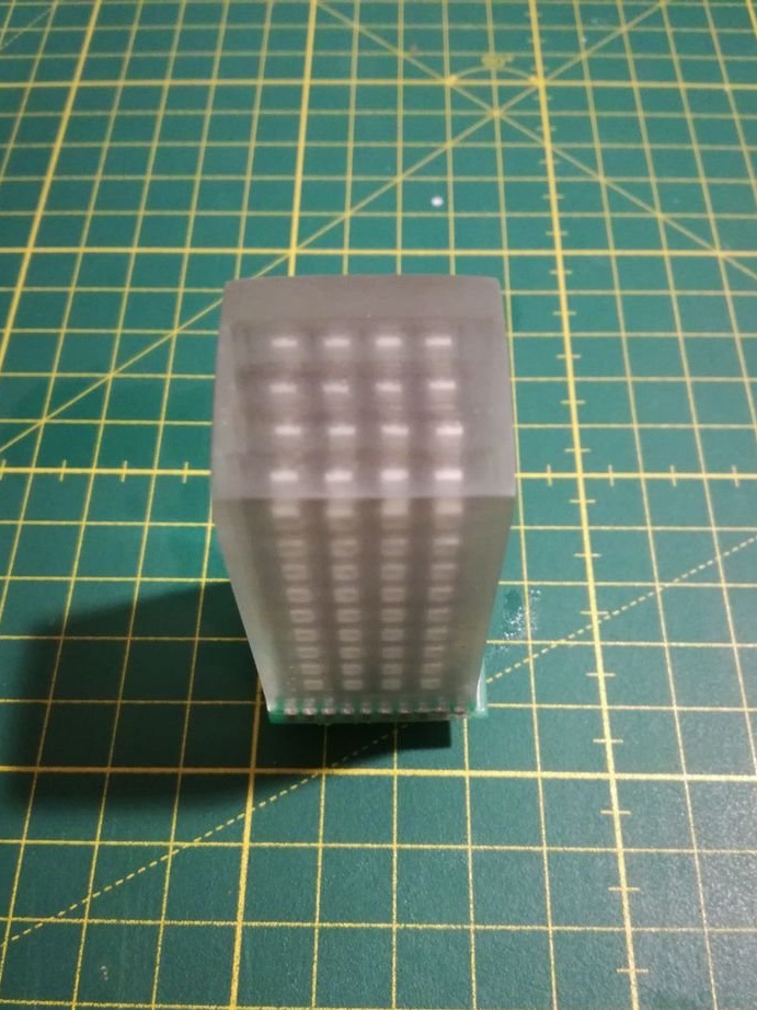
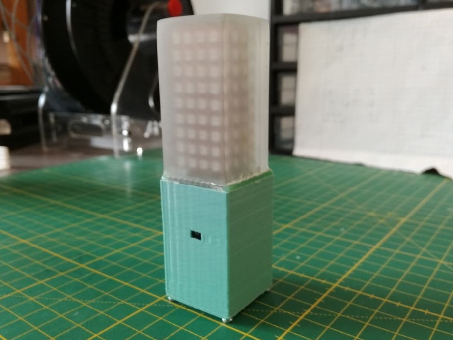
After removing the mold, you can see that the cube looks very transparent due to the smooth surface of the silicone mold. However, there will be some irregularities associated with a change in the thickness of the silicone layer. Also, the upper surface may be deformed closer to the edges.
Therefore, the author polished all the bumps with sandpaper. It was originally planned to polish the cube, in the end, it was decided that the cube looks better looking with a matte surface.
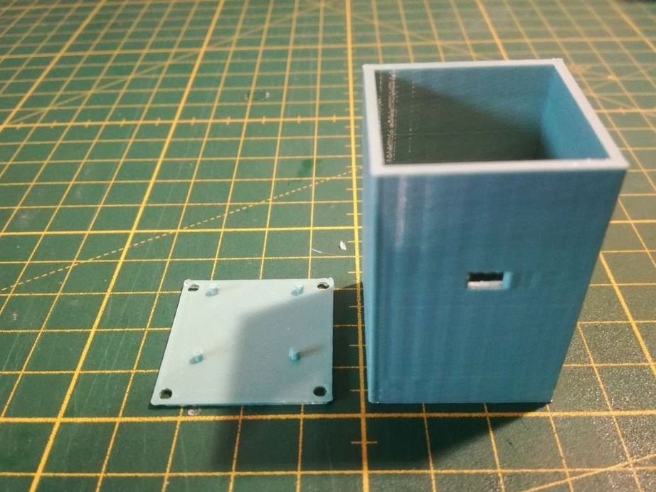
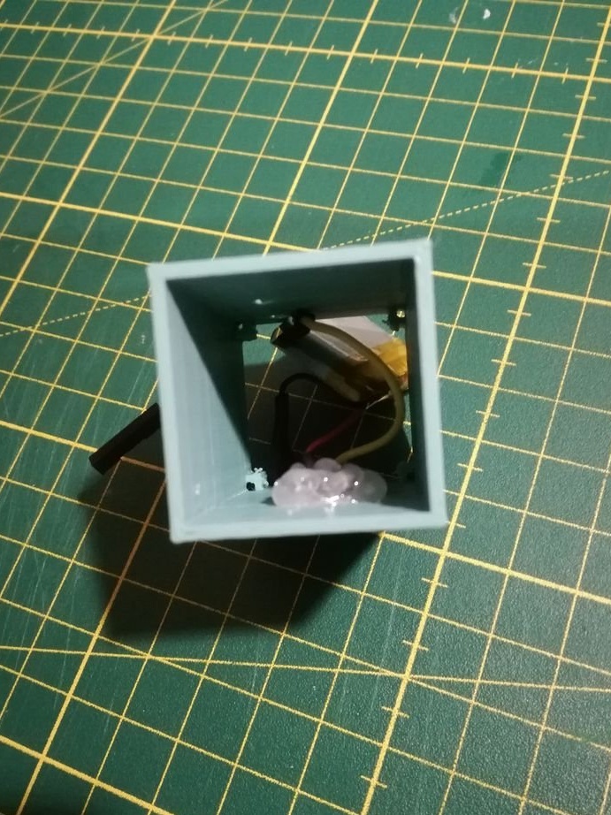
The electronics enclosure was developed using Autodesk Fusion 360, and then printed on a 3D printer. A rectangular hole in the wall for the switch and several holes in the back to install the GY-521 module using the M3 screws. Attach the TinyDuino processor board to the bottom plate, which then lock the case with the M2.2 screws. First, install the switch in the case using hot glue, then install the GY-521 module, and then carefully insert the gasket and battery.
The LED matrix was attached to the breadboard using the Dupont connectors, and the processor board can simply be connected from below. Finally, glue the bottom printed circuit board of the LED matrix to the housing using universal glue (UHU Hart).
Files for printing and firmware:
View online file: