

Greetings to all lovers of microcontroller homemade. If you are a happy owner of a home aquarium, then perhaps this article will be of interest to you. In it, I will describe in detail the entire process of creating a simple, but very useful home-made - aquacontroller, designed to facilitate the life of the owner of a small underwater world.
As you know, any successful project begins with the preparation of technical specifications. The following are the basic requirements and functions that I wanted to get from the aquacontroller:
- low cost and availability of components;
- customizable time for turning on and off the light in the aquarium;
- feeding mode (the filter turns off and starts automatically after 15 minutes);
- the inclusion of a schedule of feeding;
- measurement of temperature and humidity of ambient air (as an addition);
- display of the current date, time and other parameters on the LCD display;
- management and parameter settings through the menu using 4 buttons (Up, Down, Ok, Cancel);
Based on the above, the circuit shown in Figure 1 was born.
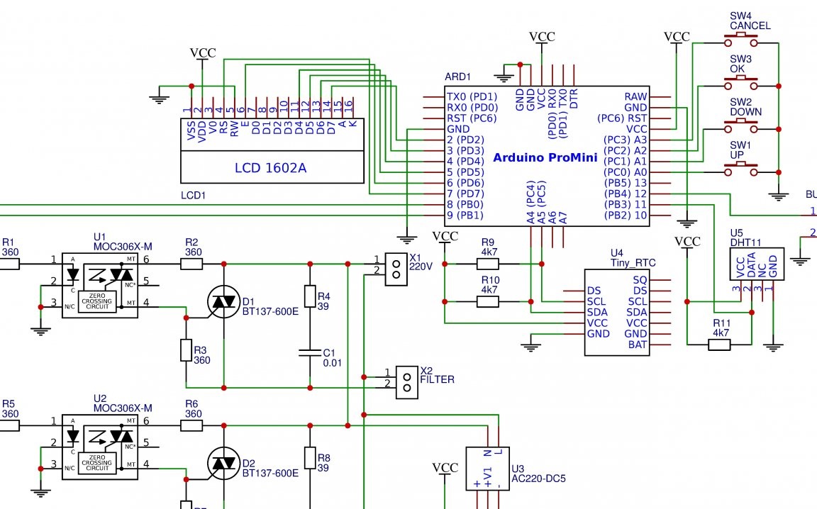
Figure 1 - Electrical diagram of the aquacontroller
The main element is the board Arduino Prominiacquired in China. As it turned out later, a controller was installed on it ATMega168 instead ATMega328. This made me tinker with the optimization of the program, since it turned out to be unbearable for this controller due to half the size of flash-memory.
A well-known 2-line 16-character LCD display was chosen for displaying information. In the project, it is connected to Arduino on a 4-wire data bus.
A digital sensor is responsible for measuring temperature and humidity. Dth11. For domestic needs it is enough. In fact, it does not have a specific purpose and is added purely as an addition to the overall picture.
To control the fluorescent lamp and the filter, I used two simistor channels made on a bunch of opto-simistor MOC3063 and power simistor BT137-600E. This allowed us to rid the circuit of mechanical relays, for which for some reason I do not feel sympathy.
Buttons of management - usual clock, without fixing.
Well, since all the settings are tied to a specific time period, the device must necessarily contain a real-time clock.In this case, I used the module Tinyrtc based on microcircuit DS1703. The module is controlled by protocol i2c and contains a connector for installing a battery, which allows you to save the date and time when the power is turned off. The external module feed is shown in photo No. 2
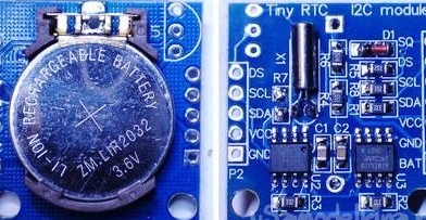
Photo No. 2 - real-time clock module
So, the requirements are defined, the scheme is drawn up - you can go to the design stage of the printed circuit board. The EasyEda online service successfully helped me cope with this task. In order not to bother with drilling holes, I decided to place all current-carrying tracks and components in the upper layer. Having twisted the details a bit in the editor, I got a PCB design with only three jumpers. The appearance of the board can be seen in figure 3.
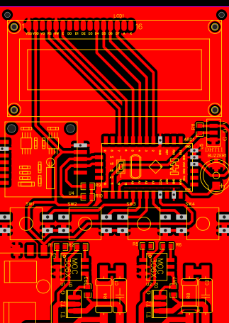
Figure 3 - The appearance of the aquacontrol circuit board
Those who want to repeat the project can download the PCB file from this link:
View online file:
View online file:
So, what points you should pay attention to. Resistance R4 and R8 - twin, all the rest are made in SMD housing 1206. Clock buttons have size 12x12. The board also has a Chinese voltage converter 220V / 5V, the appearance of which is shown in photo No. 4.
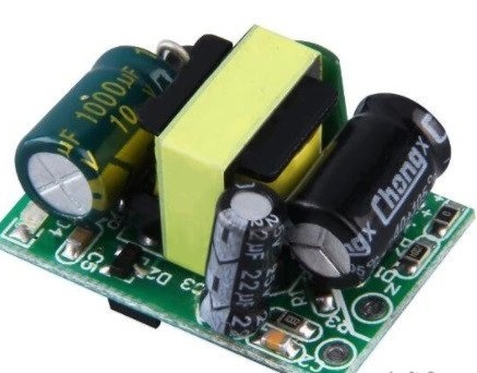
Photo No. 4 - voltage converter 220V / 5V.
The LCD screen and the real-time clock module are planned to be mounted on to-board racks, the role of which I have successfully performed by cut plastic dowels.
On this, all the features of the installation are defined and it remains only to transfer the board from the monitor screen to our physical world. A well-known method was chosen for this. LUT, implying the presence of a laser printer and iron. For those who are not familiar with this technology of the future, the process of creating a circuit board in my bathroom will be described below.
So, for starters, look for any magazine with glossy pages or a sheet of photo paper. We print the board pattern on the laser printer, without forgetting to flip it. We prepare a piece of foil-coated glass-texalite according to the size of the blank and grind the copper surface with fine-grained sandpaper to a shine. It should be something like this (photo number 5).
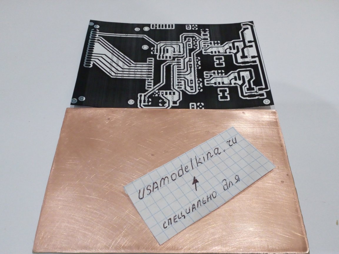
Photo No. 5 - the board is prepared for the translation of the drawing
Next, we turn the printout over to the foil and apply it to the PCB. After that, we drive the paper with a hot iron for about 3 minutes. The warm-up time here may vary depending on the temperature of the iron and the experience of the performer of this secret ritual. This visually looks something like this (photo No. 6):
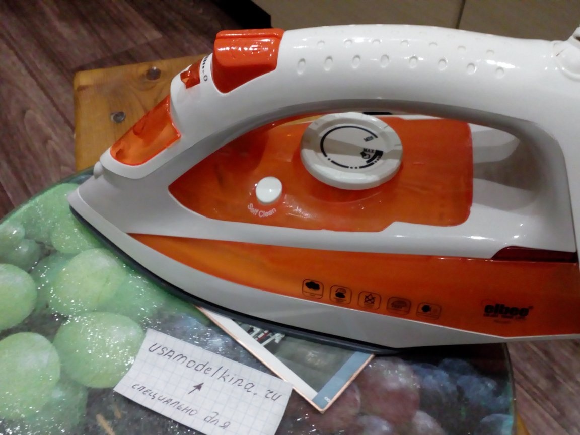
Photo No. 6 - transfer of the picture to the surface of the foil
After the paper is firmly adhered to the PCB, turn off the iron and allow the circuit board to cool. Now you need to carefully remove the paper layer and at the same time not damage the sticky toner. In order for the case to succeed, the paper must be moistened and removed by rolling with the fingertips. This process is shown more clearly in photo No. 7.
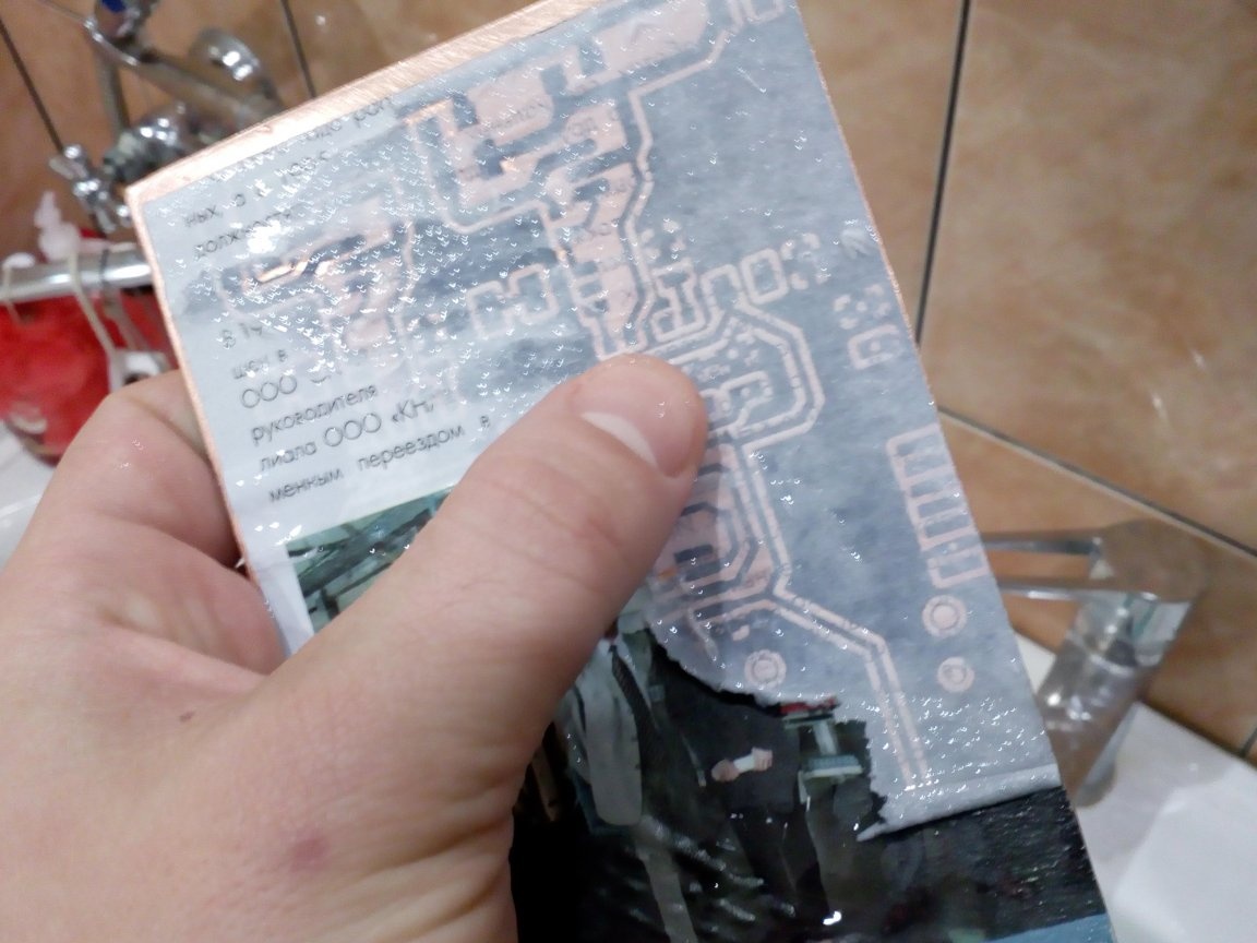
Photo No. 7 - removing paper from the circuit board
Sometimes it happens that in some places the toner simply does not stick. In this case, these areas can be completed with a permanent marker. Photo No. 8 shows the board after removing the paper. Please note that in the upper left part there is no part of the figure, which will subsequently be restored by the above method.
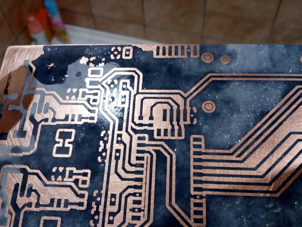
Photo No. 8 - board after removing paper
When all the unpleasant moments are eliminated, you can start etching. For this, I used a solution of ferric chloride, as one of the most affordable and safe options. After etching the board, thoroughly rinse it with a solvent to remove toner from the tracks. Then again we clean with a fine sandpaper, degrease and tin. The result is shown in photo No. 9.
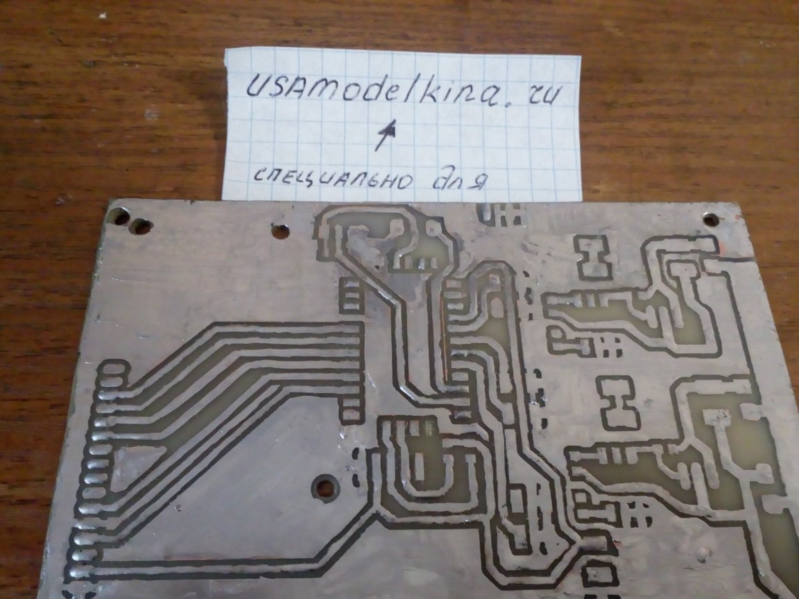
Photo No. 9 - the board is ready to install radio components
One of the main stages is completed. The next stage is the installation and soldering of radio components. This is a creative and purely individual process. If you have any questions, I’m ready to answer them in the comments, but now I’ll just show you what I got (photo 10):
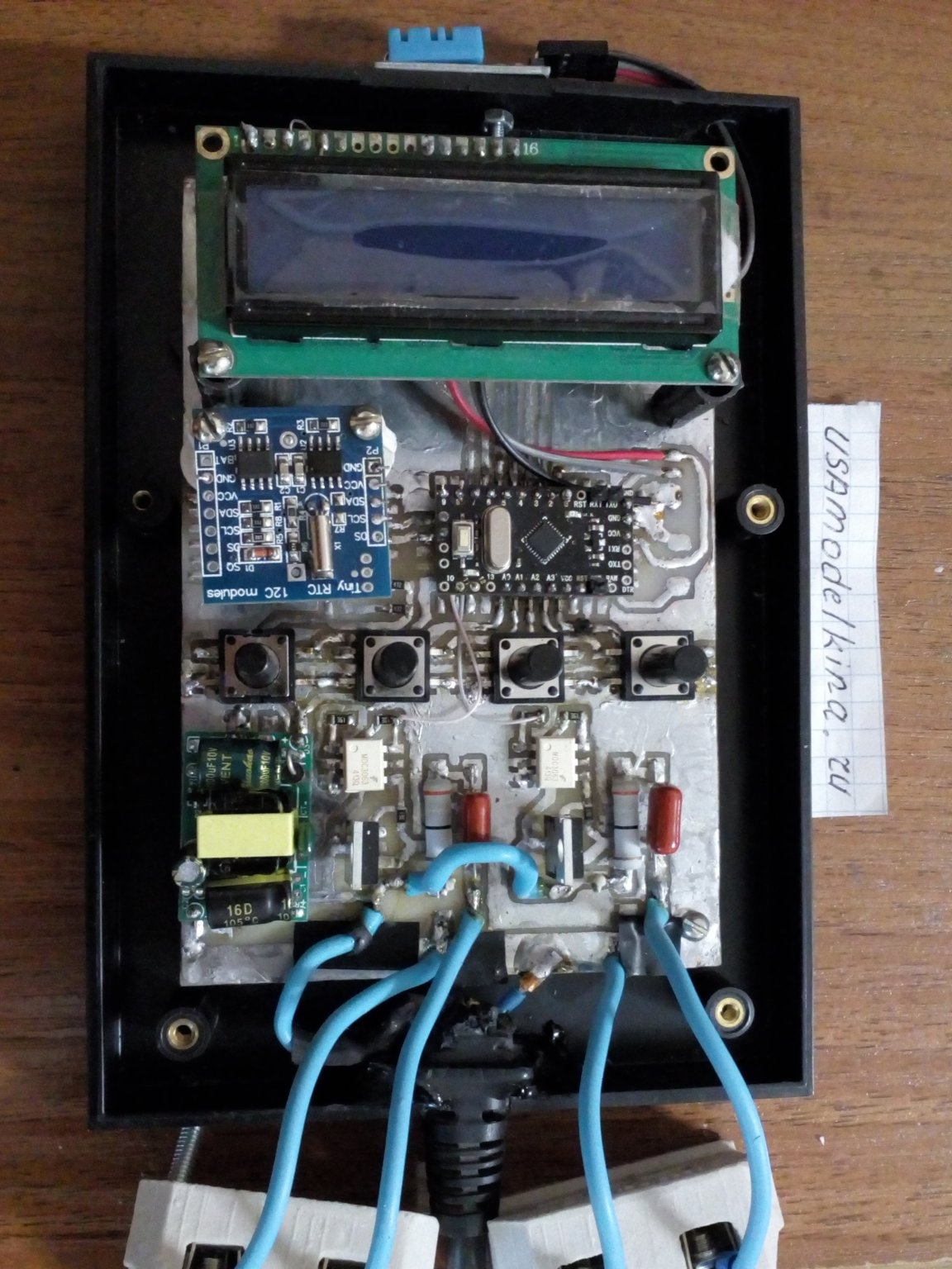
Photo No. 10 - a board with sealed components
As I wrote above, the display and the clock module are raised above the board with plastic racks made of dowels for quick installation, and their contacts are soldered to the board with thin wires.The temperature and humidity sensor is displayed separately on top of the device. In my opinion, with this arrangement, the readings will be more accurate. For the lighting channels and the filter, two external outlets are displayed at the bottom of the board. Also, the height of the buttons was insufficient, so I plan to increase them with plastic bushings. After some manipulations, the device takes on an almost finished appearance, shown in photo No. 11.
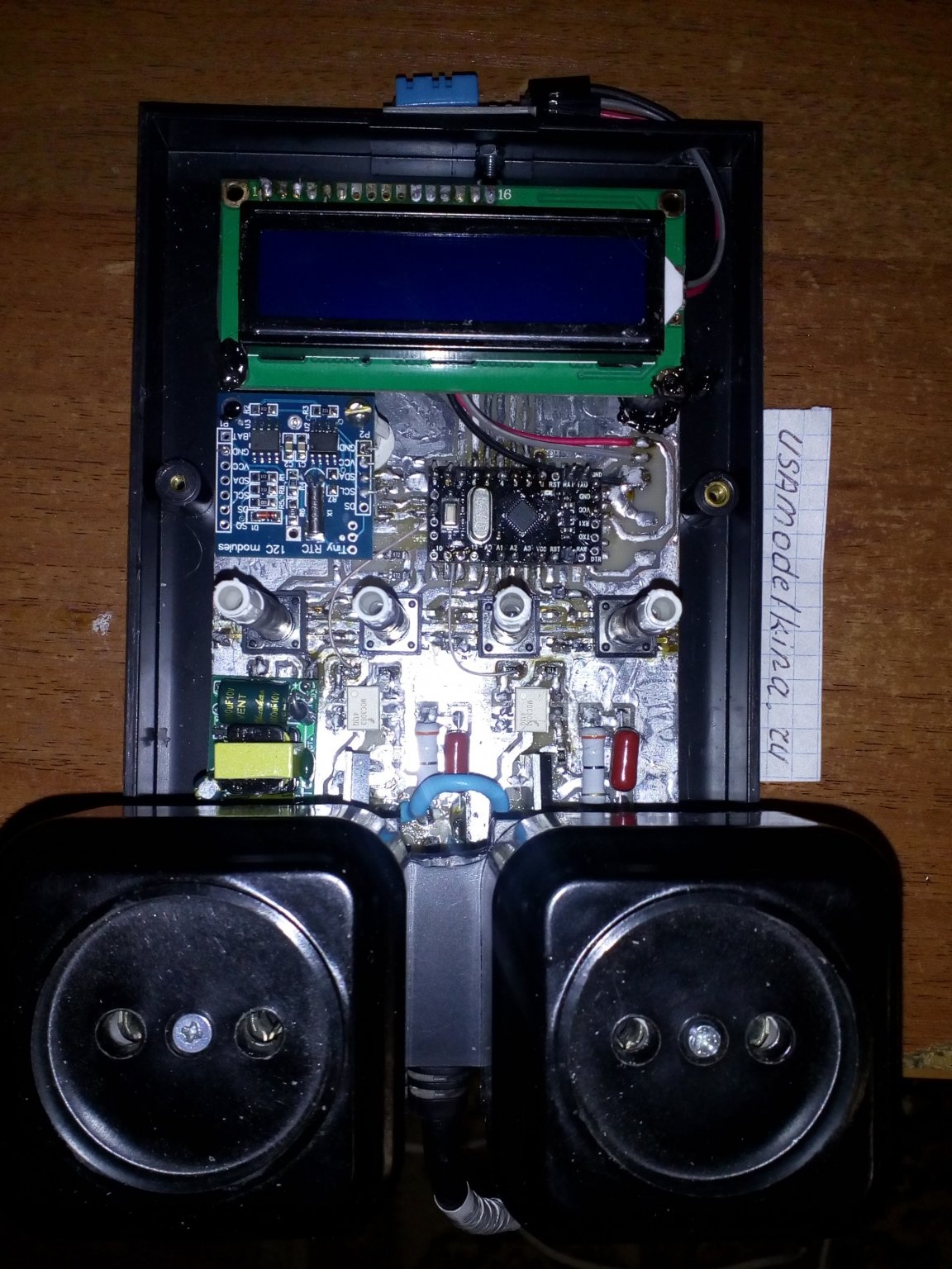
Photo No. 11 - aquacontroller without housing
Before you seal the top of the case, you must write the firmware in Arduino ProMini. To do this, I put pins on the board connected to the contacts Vcc, GND, Rx and TX. To program Arduino ProMini easiest using USB programmer, but this was not available. His role was successfully performed by another board Arduino uno with the controller removed. I will not go into the details of this process, since there are many articles on this subject on the Internet. I will give only photo No. 12 for clarity.
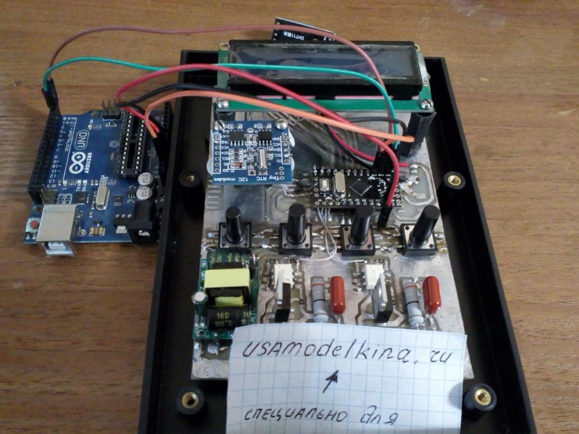
Photo No. 12 - preparation for firmware
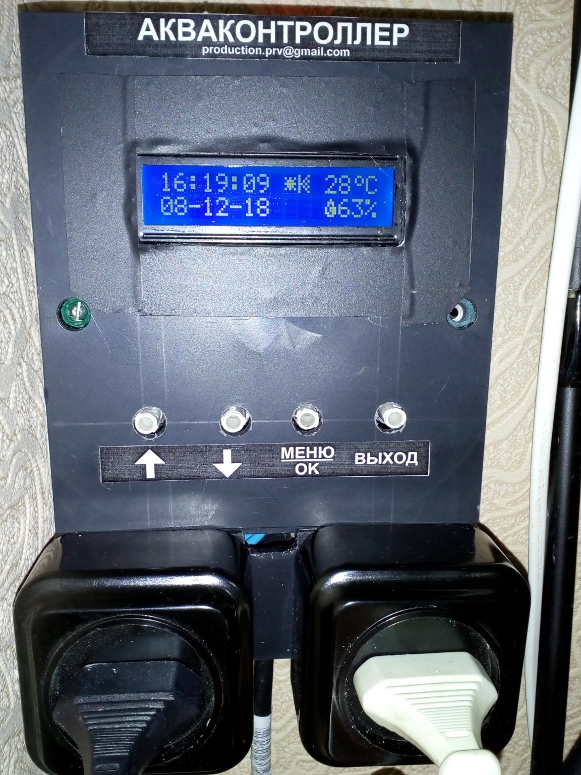
Now let's talk about the program itself. When you turn on the power, the main screen is displayed. It displays information about the current date, time, temperature and humidity. Also, several special characters are displayed depending on the current state of the system, namely: the light is on - the sun icon; light off - moon icon; filter on - filter icon; feeding is in progress - fish icon. When you click OK, the user enters a menu where it is possible to configure parameters such as:
- lighting control mode. In this section, you can turn the light on and off manually by selecting the corresponding menu item, and also set the time for turning on and off according to the schedule.
- filter control mode. Allows you to turn the filter on and off manually, select the “feeding” function (fedding), and set the feeding schedule. In feeding mode, the filter stops and restores automatically after 15 minutes.
- setting the current date.
- setting the current time. Date and time data are recorded in the clock module and when the power is turned off, they are not reset if a battery is installed on it.
For a better understanding, figure 13 shows the menu structure.
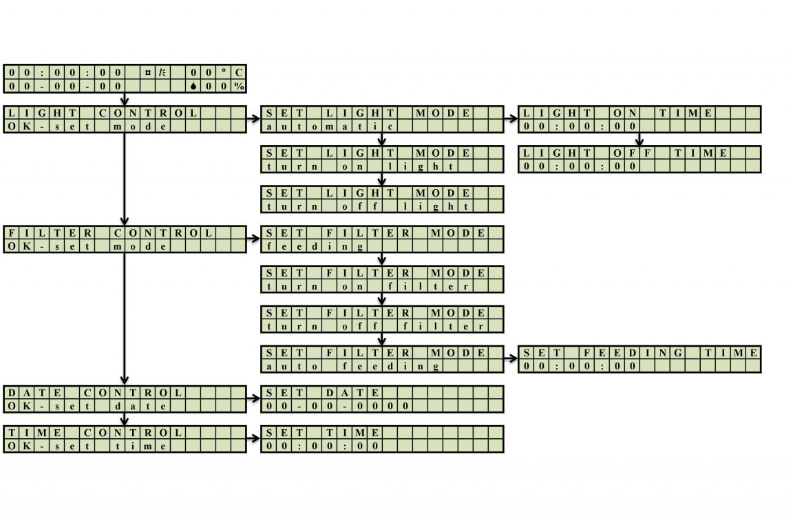
Figure №15 - menu structure of the aquacontroller.
Download firmware for Arduino Pro Mini and all the necessary libraries can be this link
After writing the program to the microcontroller, you can close the case and proceed to the tests in real conditions. About a week of operation passed before writing this article. The aquacontroller worked perfectly without any malfunctioning, saving me from constantly pulling the forks if necessary to feed the fish or turn off the lights. The result of my efforts is shown in photo No. 16.
Photo No. 16 - aquacontroller in operation