
Greetings the inhabitants of our site!
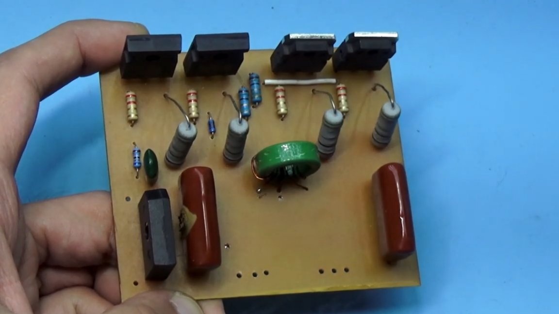
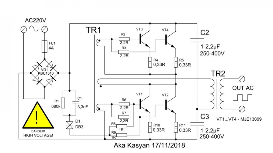
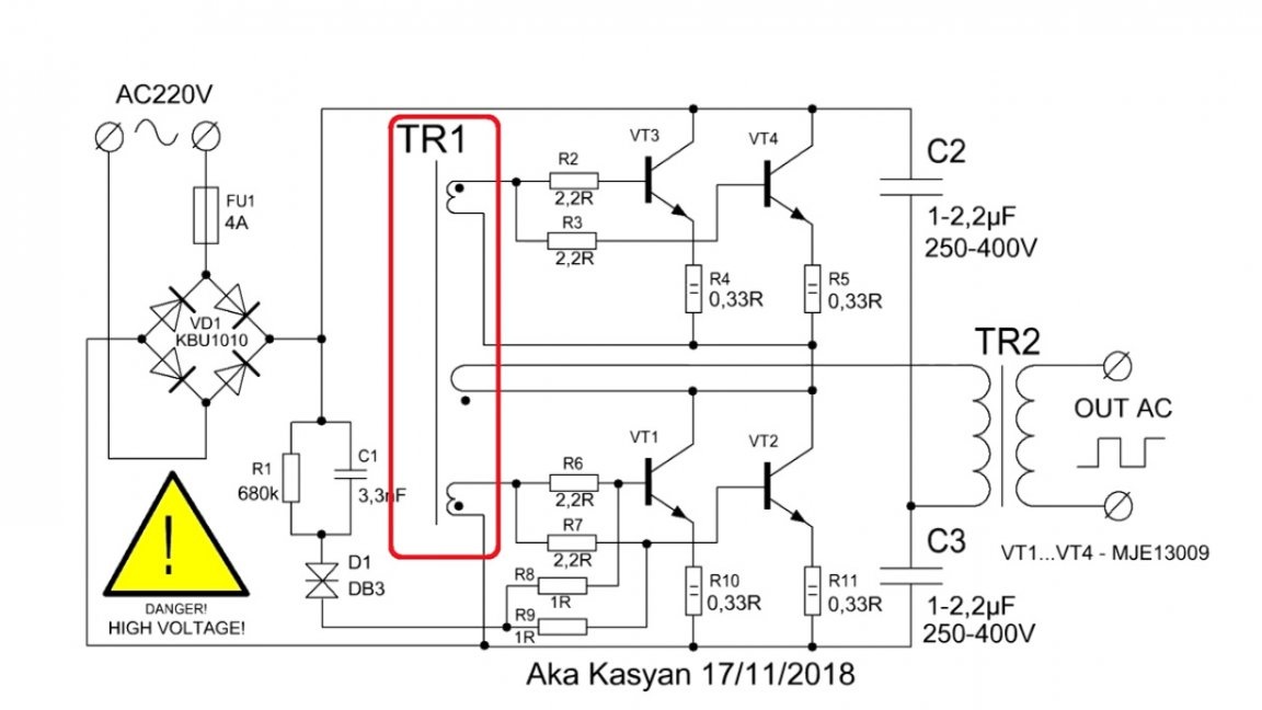
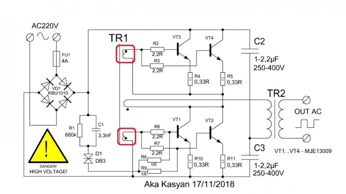
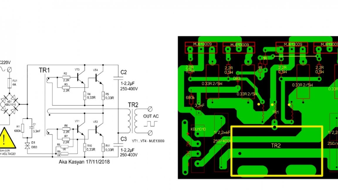
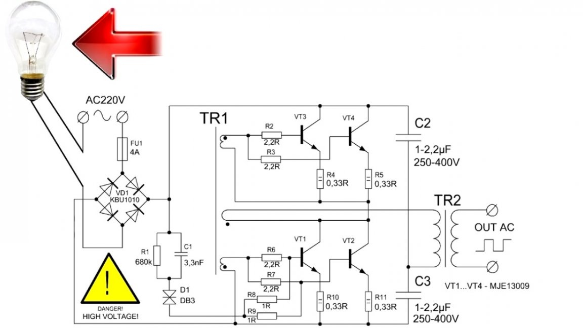
Today we will squeeze half a kilowatt of pure power from this simple scheme:
Attention! This material is intended for informational purposes only. The author does not recommend repeating what he saw, especially if you are just starting to get involved in electronics. When working with high voltage always follow the safety rules. Do not touch the device (board) during operation. When carrying out adjustment work, make sure that the device is disconnected from the network.
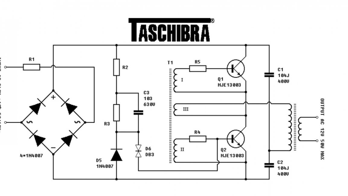
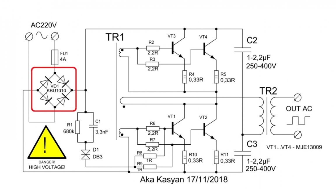
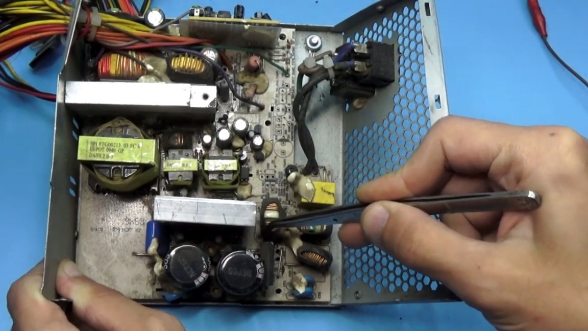
The author of this homemade product is AKA KASYAN. Here is a classic scheme electronic transformer for office low-voltage halogen lamps - half-bridge self-generating switching power supply. We have 2 transformers: power and feedback transformer.
The power of the circuit depends on some components: input rectifier, power switches, capacities of the floor of the bridge and power pulse transformer.
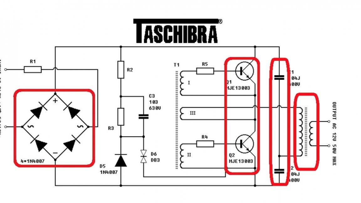
If we replace them, roughly speaking, with more powerful ones, we will be able to achieve greater output power in general. The active components of our circuit are transistors - these are high voltage reverse conductivity switches.
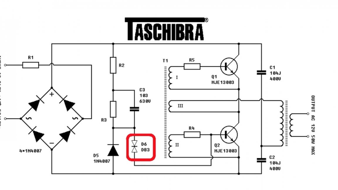
The circuit is triggered by a DB3 symmetrical dinistor.
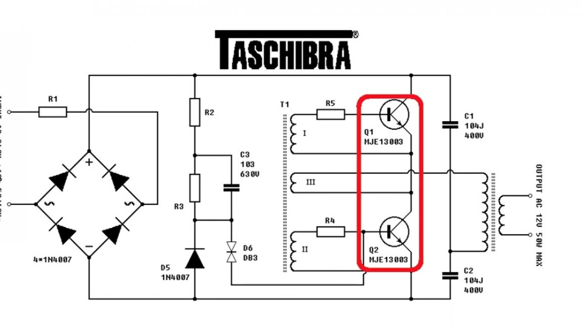
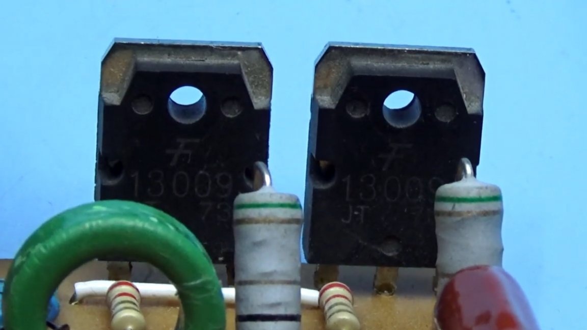
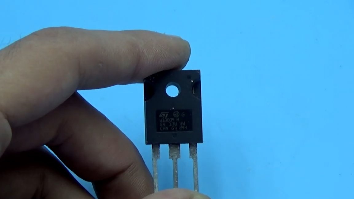
The most popular budget and powerful high-voltage transistors that the author knows are MJE13009, which he will use.
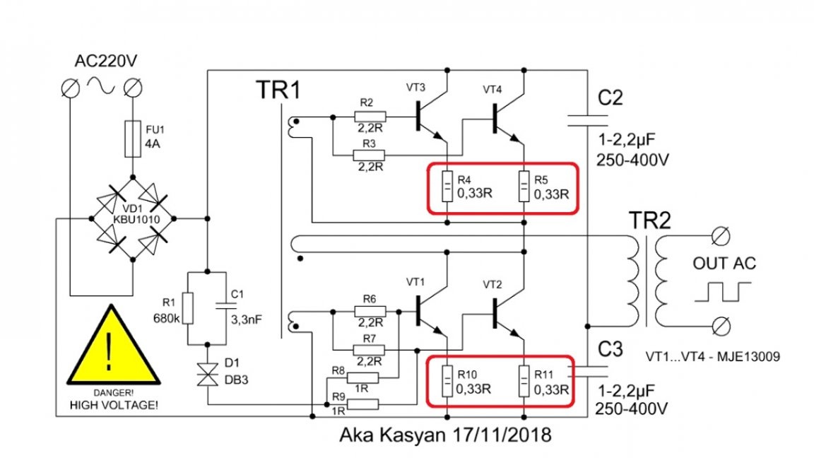
But the circuit does not shine with high efficiency. One key pair for our purposes may not be enough, so a second pair is added to the scheme. The result is this:
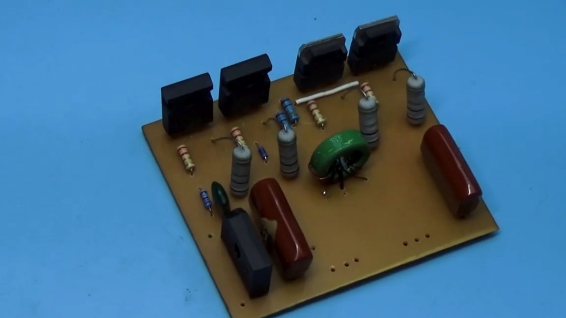
Powerful low-resistance resistors in the emitter circuits of the transistors are equalizing, helping to uniformly load all transistors.
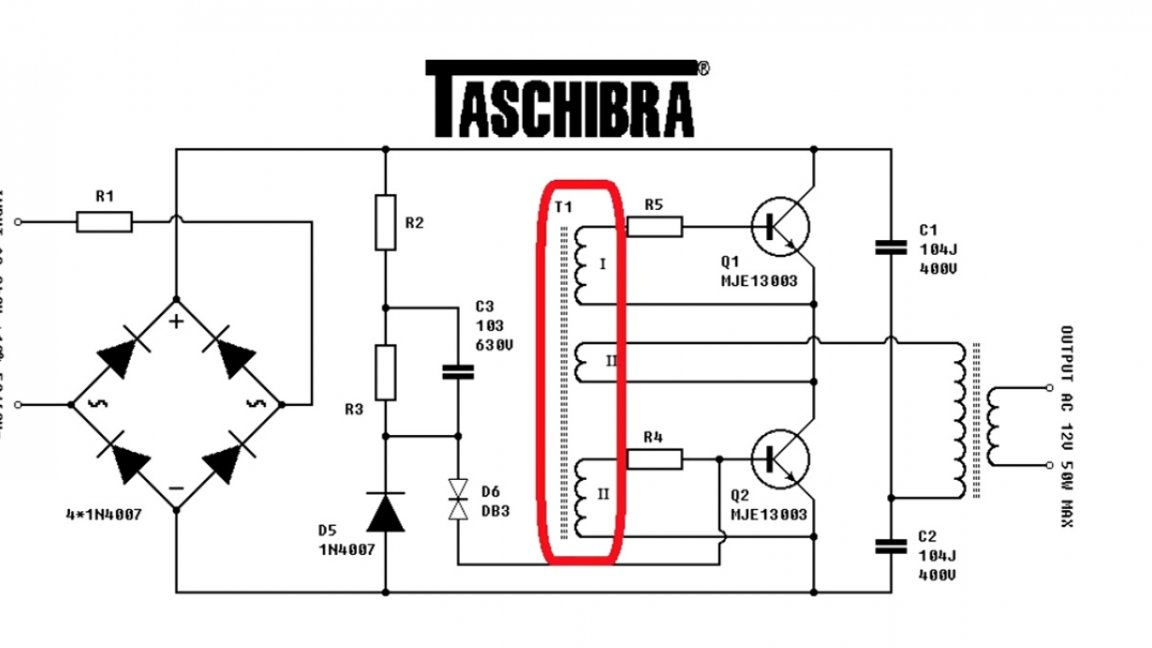
Power transformer toroidal, was wound a very long time for some kind of project. The overall power of such a transformer is more than 1 kW.
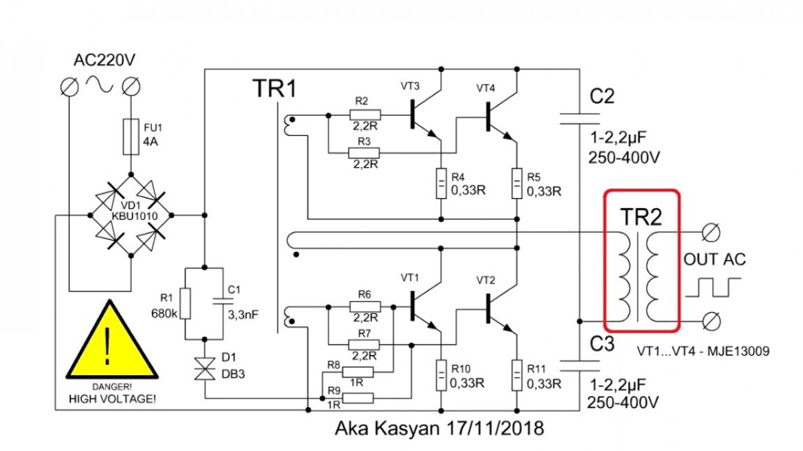
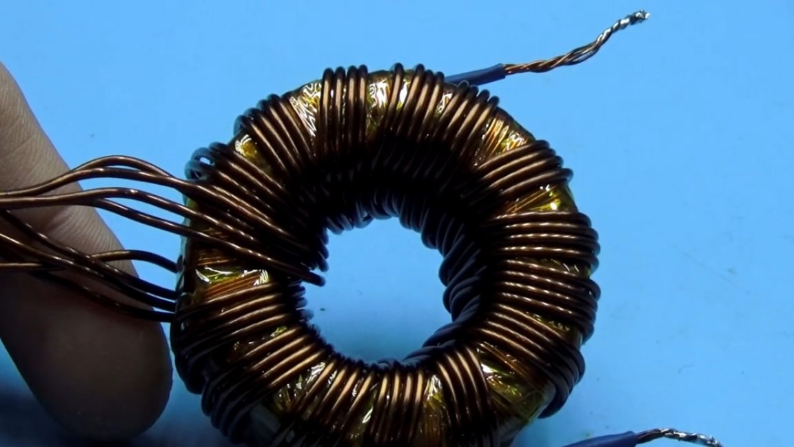
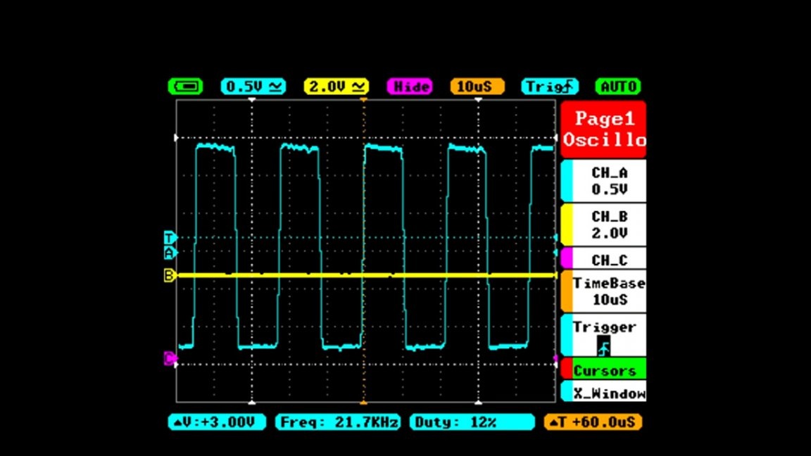
Since the converter is a self-generating type, and the operating frequency depends heavily on some parameters and is extremely unstable, it is not easy to accurately calculate the power transformer, but approximate calculation can be done using specialized programs knowing the initial frequency of the converter with a small load, in this case 22 kHz.
In the calculation program, select the half-bridge topology and indicate the remaining data.


The author did not cite the winding data of his transformer. You understand, you will probably have a different core, and the winding parameters will be different.
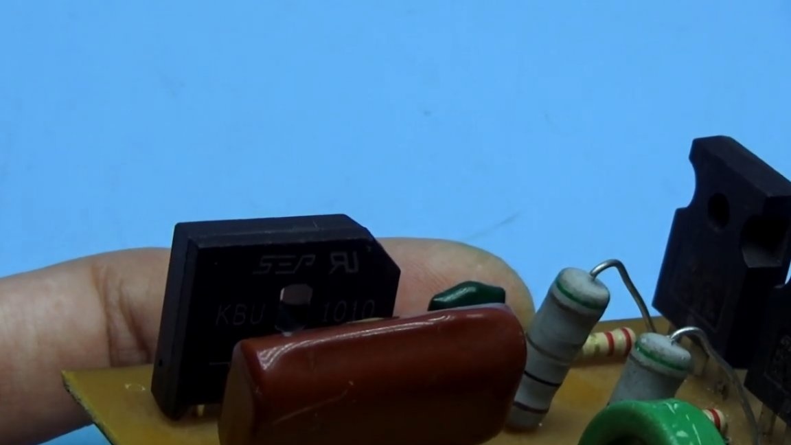
Diode bridge.
This is our 10-amp assembly with a reverse voltage of 1000V, it is heated, but not very much. For long-term work, it is worth installing it on a radiator.
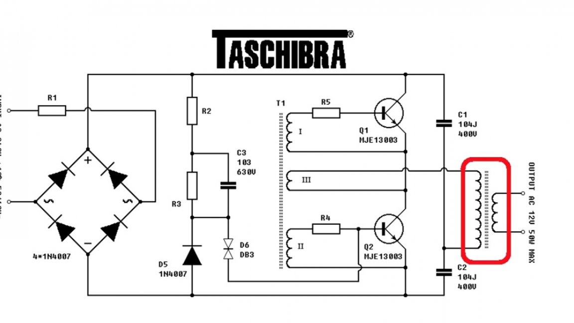
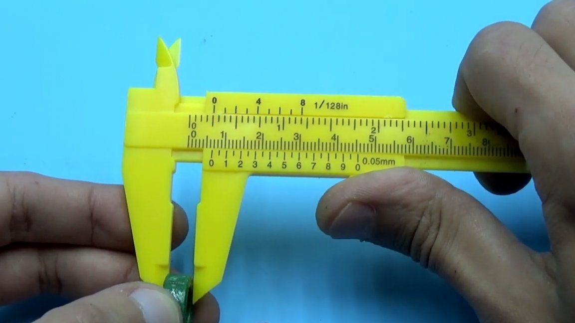
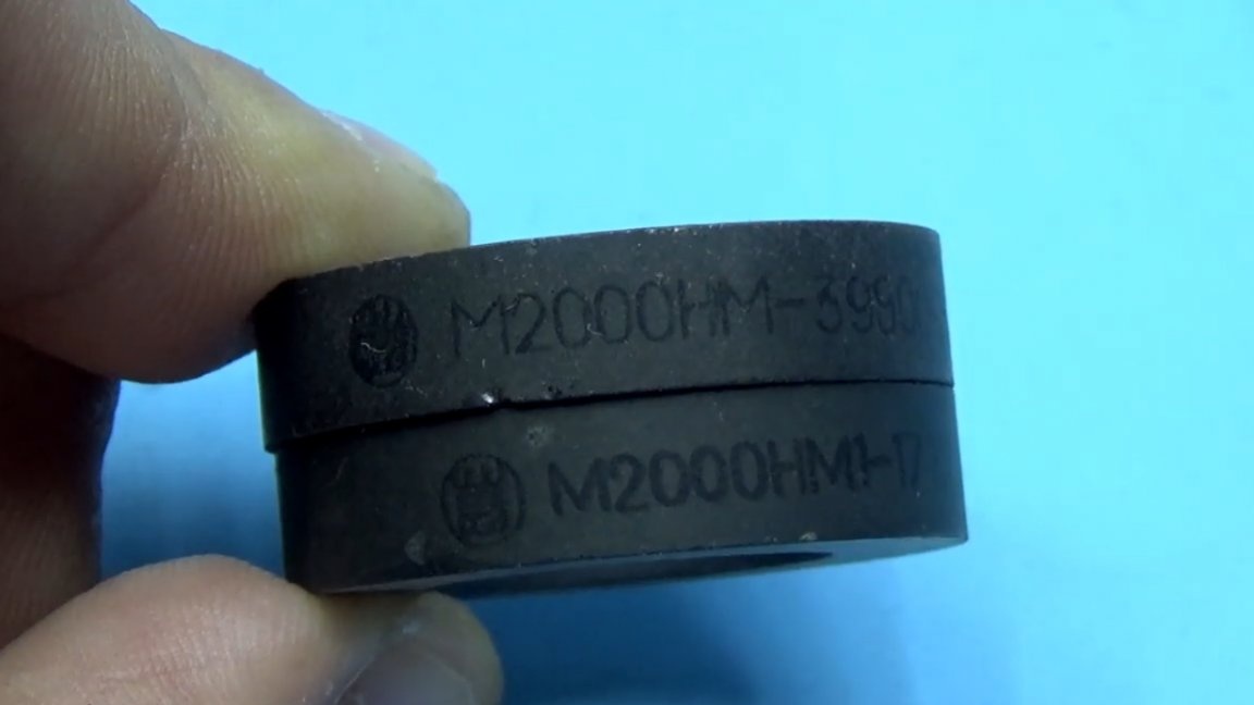
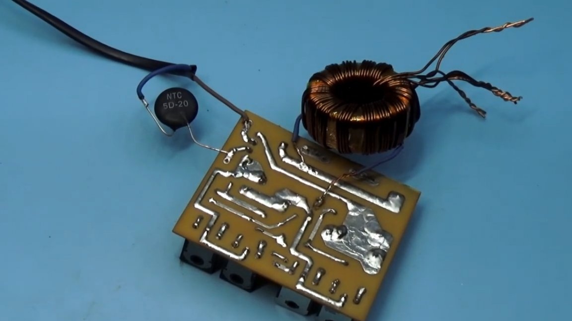
Feedback transformerferrite ring, dimensions included:
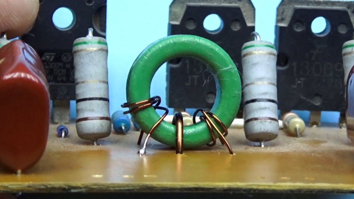

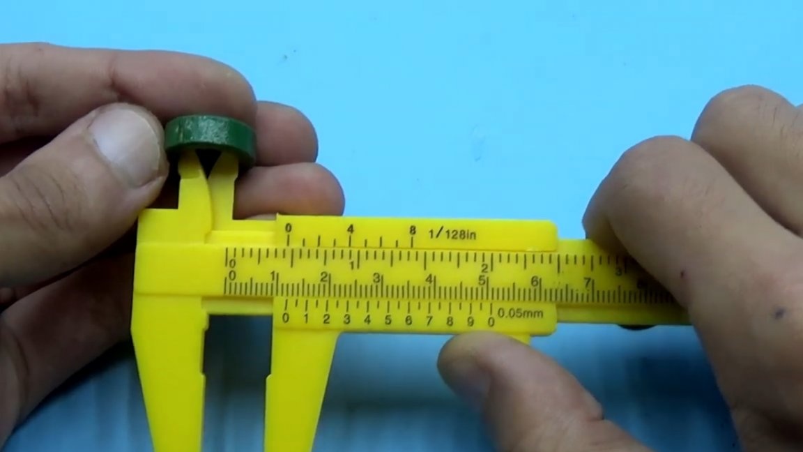
The author tore this ring from the computer’s power supply, but here please be more careful, such rings are on the input side of the power supply on the 220V line, and not on the output. Yellow-white, green-blue and other rings that are on the output of the power supply are made of powder iron and will not work for our purposes. We need a ferrite ring.
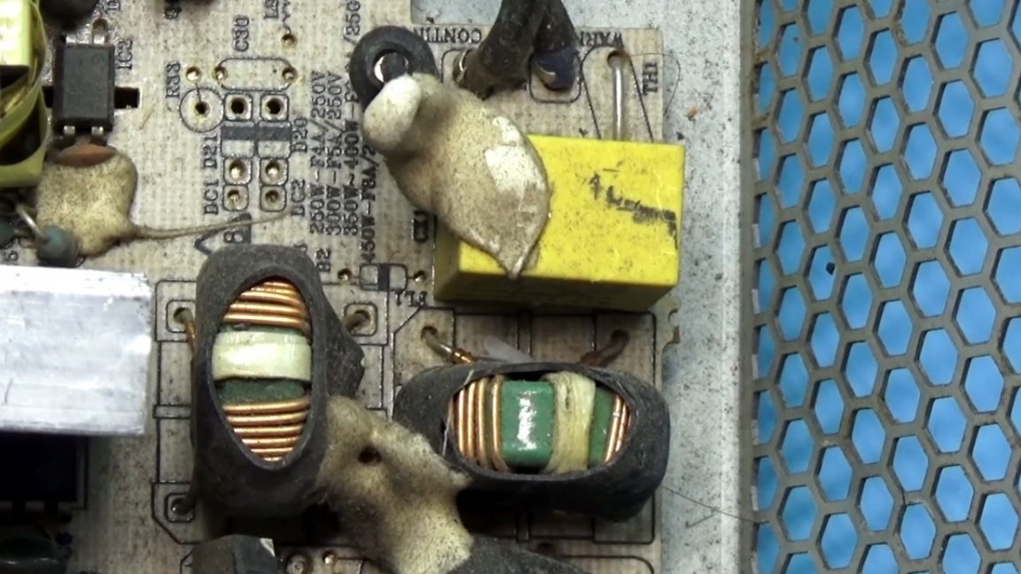
The author also used other ferrite rings with permeabilities from 1500 to 3000, worked flawlessly.

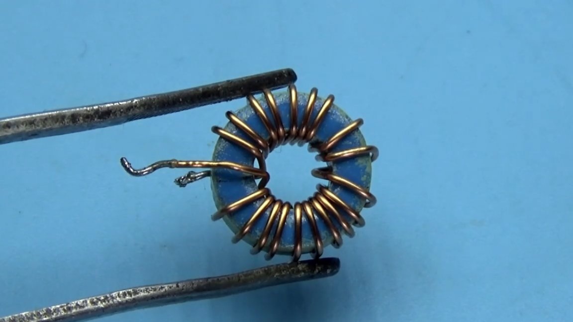
The base windings are identical and contain 3 turns of 0.5 mm wire. Feedback winding only 1 not a complete turn with a wire of 1.25 mm.
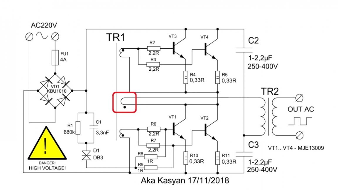
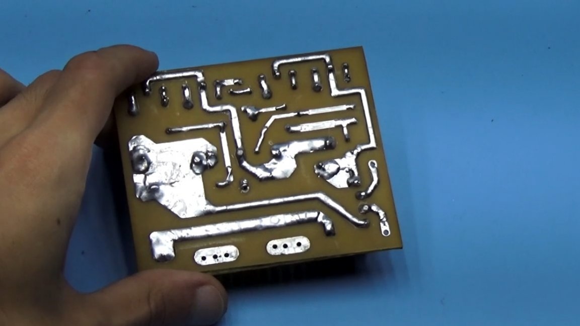
Many people have questions related to the phasing of the windings of a feedback transformer. If the beginning and end of the windings are mixed up, then nothing will work. The author repeatedly told and showed in his previous projects how everything connects, but questions still arise, so if anyone decides to repeat it, just collect everything from the board.
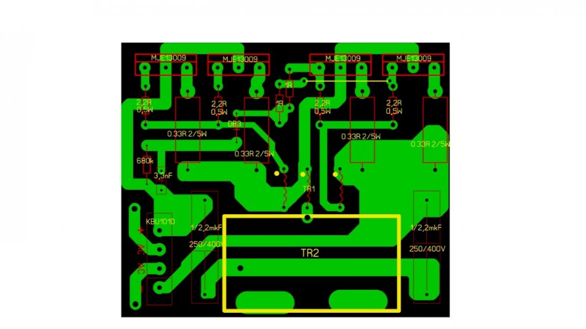
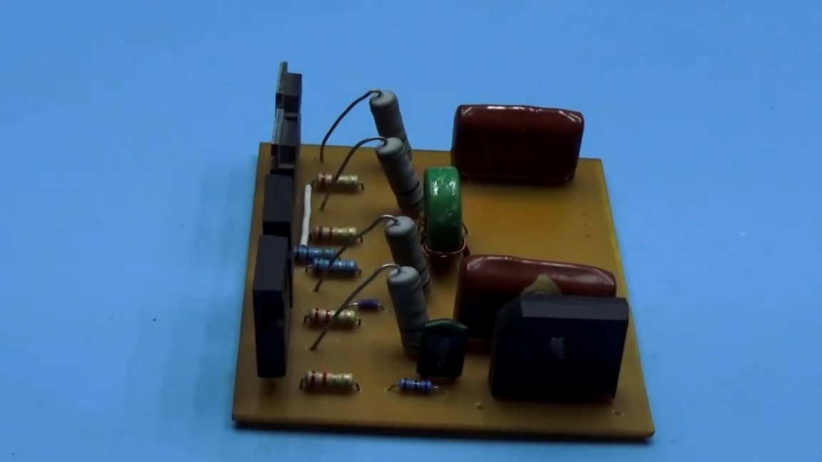
Well, look carefully at these photos:
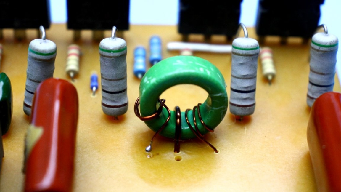
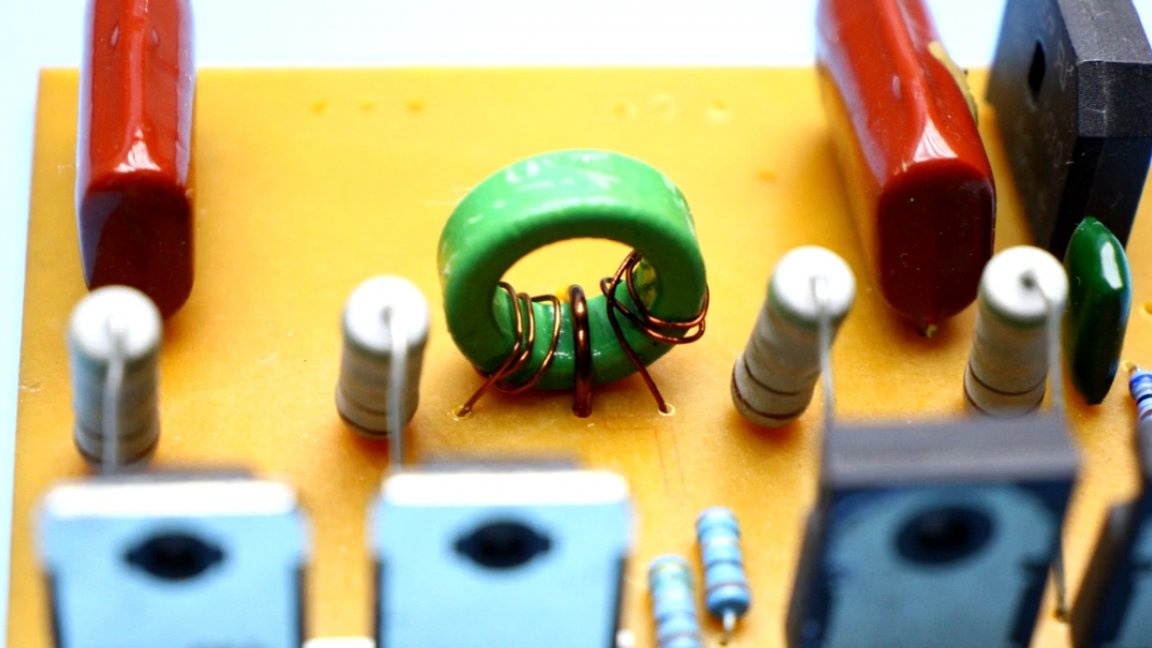
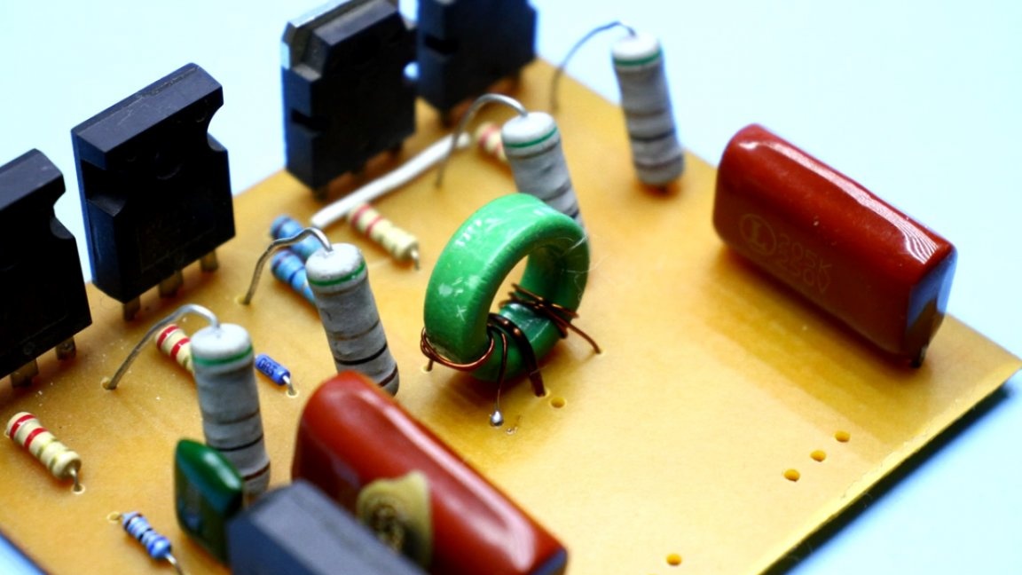
Naturally, on the diagram and on the board, the dots mark the beginning of all windings.
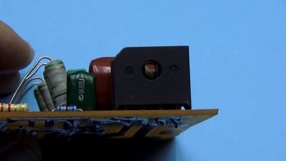
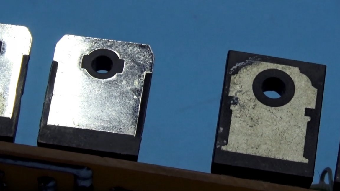
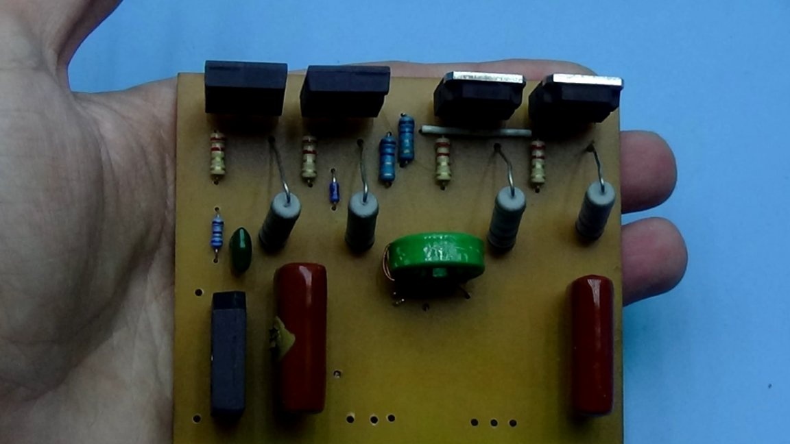
Power transistors are installed on a common heat sink. Their substrates are insulated, for example, with mica gasket or with more modern heat-conducting insulating material.
Well, as if everything is ready, you can test. Such experiments are best done in the courtyard, since it is impossible to predict when the circuit withers. And in general, in our business you can never be sure that the assembled and established design will work as it should, because no one canceled the Chinese dirty tricks in the form of fake transistors or a diode bridge.
Precautionary measures. The first start-up is always done through a safety lamp for 40-60W, 220V.
Never, under any circumstances, touch the board during operation! Never close the output of an electronic transformer, it will simply explode, since the circuit has no protections besides the input fuse, but it burns out in spite only after the power transistors burst.
The voltage at the output of our transformer is variable. The author straightened to an unclean constant for more or less adequate measurements, but naturally we will have additional losses in the rectifier. The rectifier itself is STTH6003. Under the case there are 2 powerful diodes of 30A each connected to a common cathode. Such are used in welding inverters.
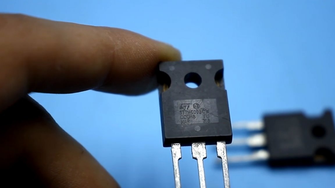
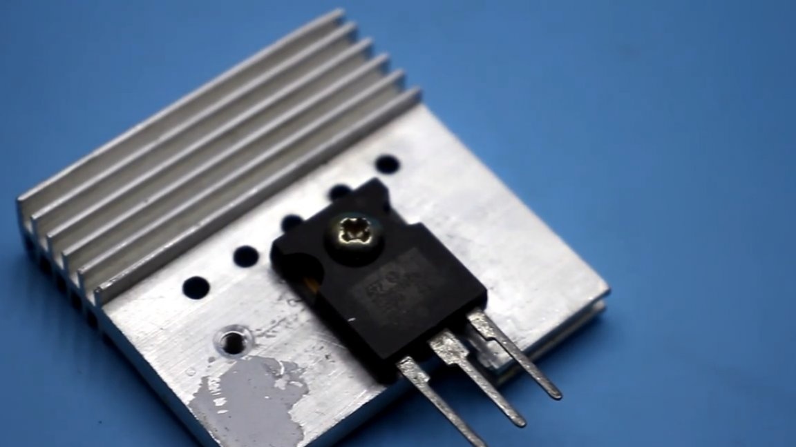
Install the rectifier on the radiator and in a good way.
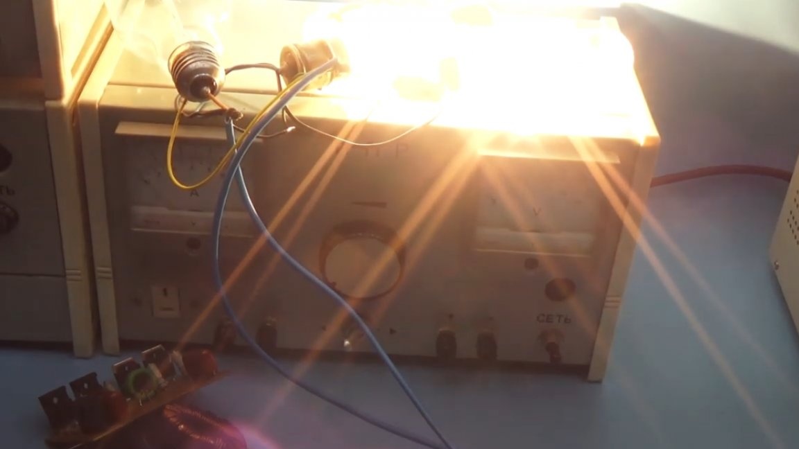
We will load the transformer with the good old and damn powerful lamps from the movie projector and something else.
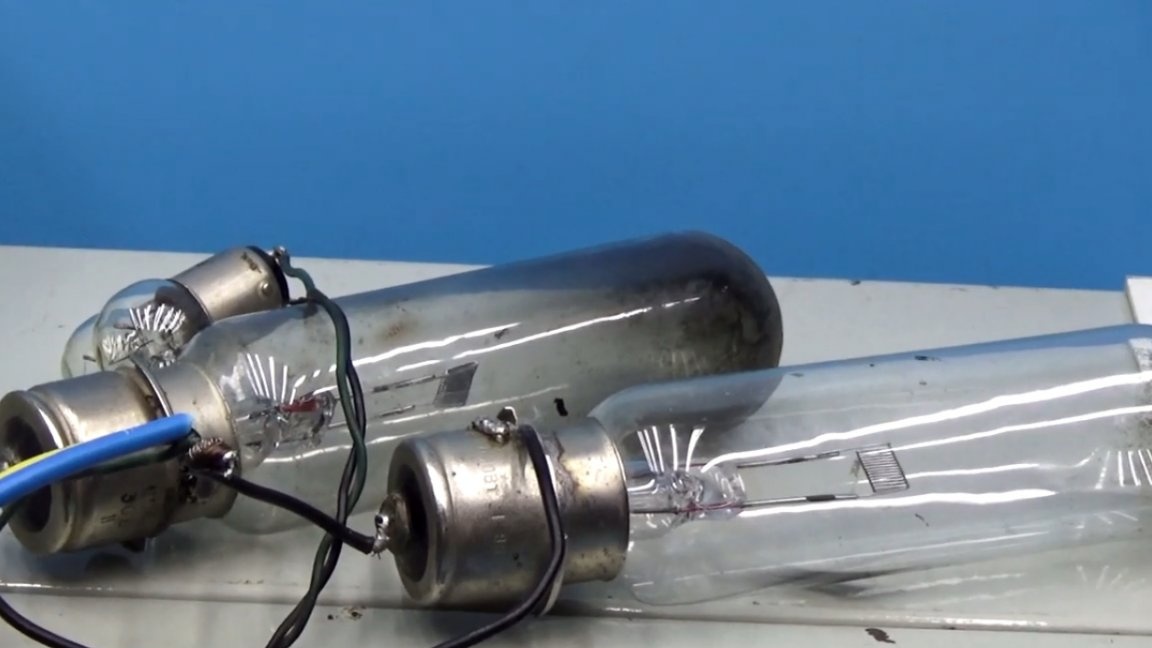
Since these lamps in cold state have very low resistance of the filament, and therefore, at the initial moment they will consume much more current from our power supply unit, we attach a powerful thermistor to the input of the circuit, it will limit the current until the lamps warm up.
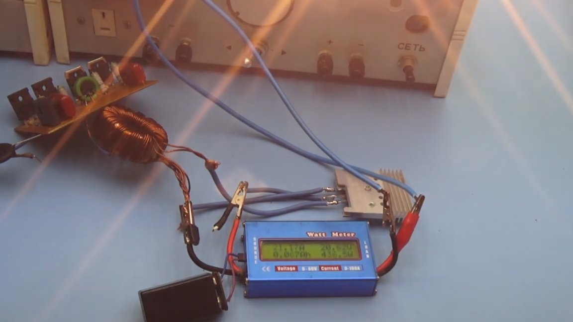
We will not turn on the power supply for a long time, since the power transistors are completely without cooling. The maximum that could be obtained with such a load is 460-470W of net output power.
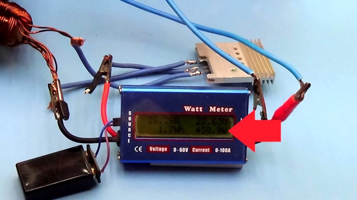
Given the losses in the wattmeter, as well as in the rectifier and on the wires, I think that no one will doubt that the circuit will give out 0.5 kW. The circuit itself is very simple, not the most capricious, but the load capacity, one might say, is at its best. But repeating it, especially for beginner hams, is not recommended, despite the fact that such schematic solutions are used in industrial power supplies for office low-voltage halogen lamps.
Is it possible to increase the circuit power even more? In theory, you can. But it is not in vain that this circuit is not used in power supplies with a power of more than 250-300W. For such a simple half-bridge circuit, this is the limit.
That's all. Thank you for attention. See you soon!
Video: