
This homemade, which was invented by the author of Instructables under the nickname thatguyer, will be useful to parents of children who have not yet learned the numbers. How can I explain to them that “we leave in ten minutes” or “in five minutes give the toy to your brother” if they do not understand the readings of either an analogue or digital clock, and also do not know how long the minute is? The master tried the kitchen timer, but it turned out that the linear scale is more visible than angles and sectors. The design replaces a whole set of hourglass, as the shutter speed can be changed.
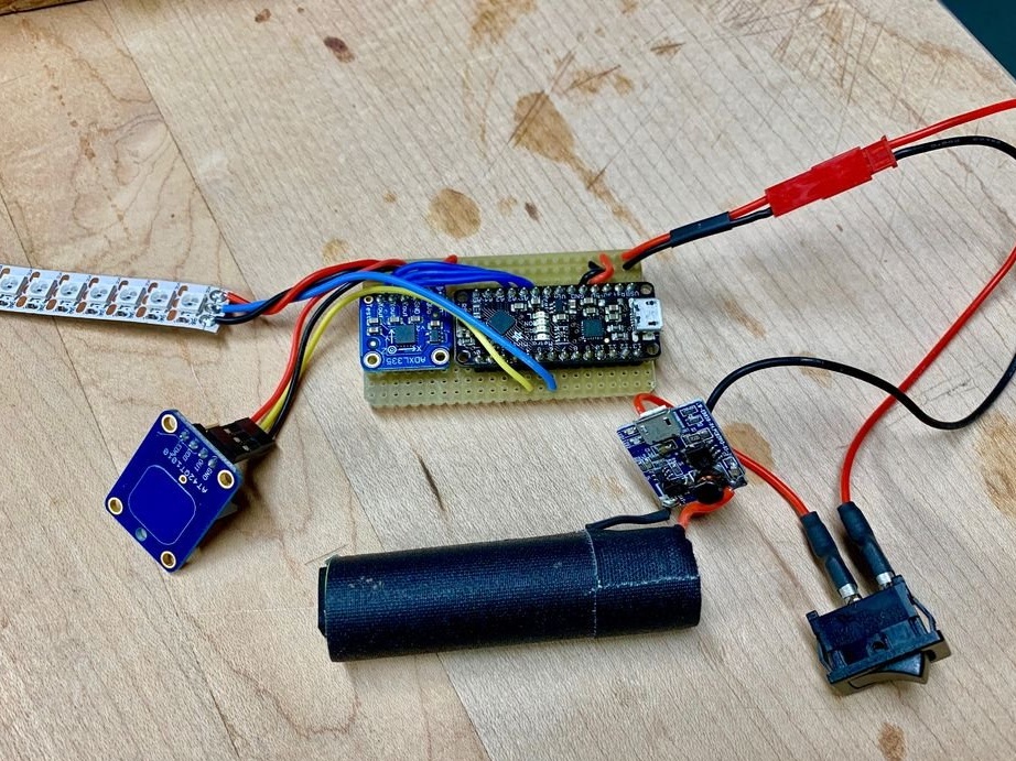
Applied to device Arduino- compatible Adafruit Metro board, if you use another, it is important to have at least three analog inputs. Information is output to a piece of tape with addressable WS2812 LEDs with a density of 144 LEDs per meter. Two ready-made boards by Adafruit were also used for control - one with a touch button, the other with a three-axis accelerometer. The power source is the inside of the power bank - the battery along with the board, but it is better not to remove this device from their case at all, since the homemade product is fed from it in the usual way - through a five-volt output.
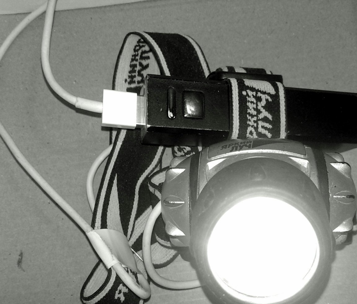
By disassembling the powerbank, the master dispenses with the USB cable, soldering the wires parallel to the output connector. In vain: so what, and finding a cord with a large USB plug today is not a problem. You need to take a damaged cord, on which the Micro USB or Lightning plug “fell off” on the opposite side, remove it and pull the wires out of the cord. Here, for example, how the translator applied such a cord:
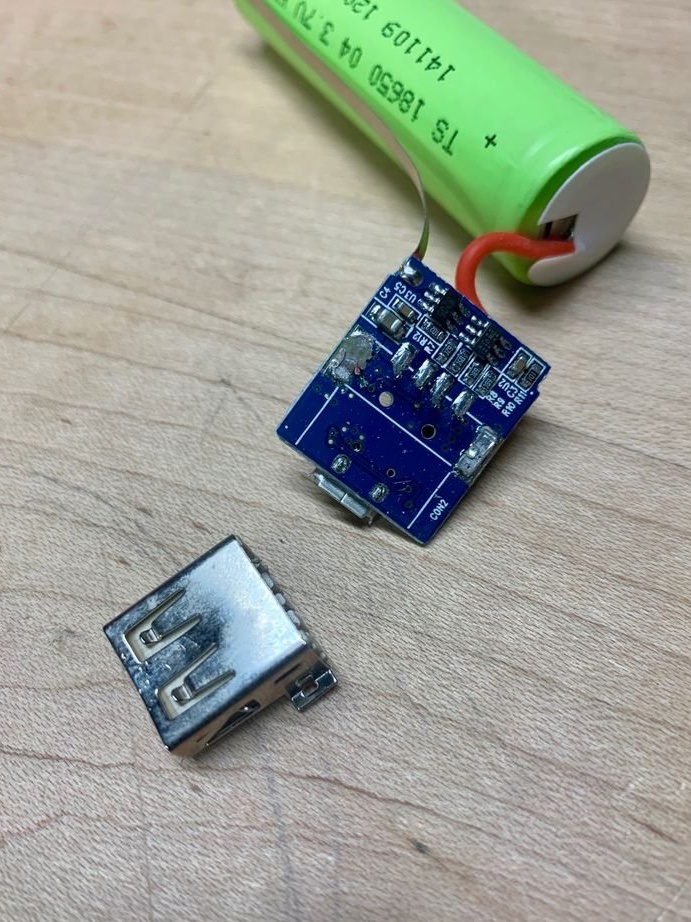
But thatguyer artificially creates difficulties for himself. In every possible way trying not to tear anything and not to close, he slightly modifies the powerbark. First removes the output connector from his board:
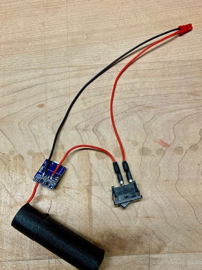
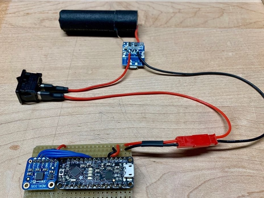
Then, instead of it, it connects the JST connector via wires through a switch, which, in turn, is connected not by soldering, but by RPPI connectors. The counterpart of the JST-connector is lying still and waiting for connection to the circuit.
The optional option is ready, the next steps are the same regardless of whether you remade the power bank or left it in the case together with the cord mentioned above.
Thatguyer installs an Arduino-compatible board and accelerometer module on the breadboard:
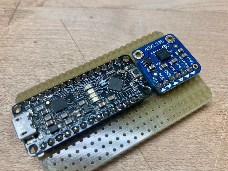
How to solder them will not work. In order for everything to work, two conditions must be met. The first is that the USB connector is on the edge of the breadboard, so it’s more convenient to connect a cable to it. The second is to correctly orient the accelerometer. This is easier than flipping the planet’s gravity.
The master selects on the breadboard the buses that will be the plus and the common wire, and connects the corresponding conclusions of the accelerometer and the Arduino-compatible board to them. Then it connects one to another like this: the output of the X axis - to the analog input A2, Y - to A1, Z - to A0:
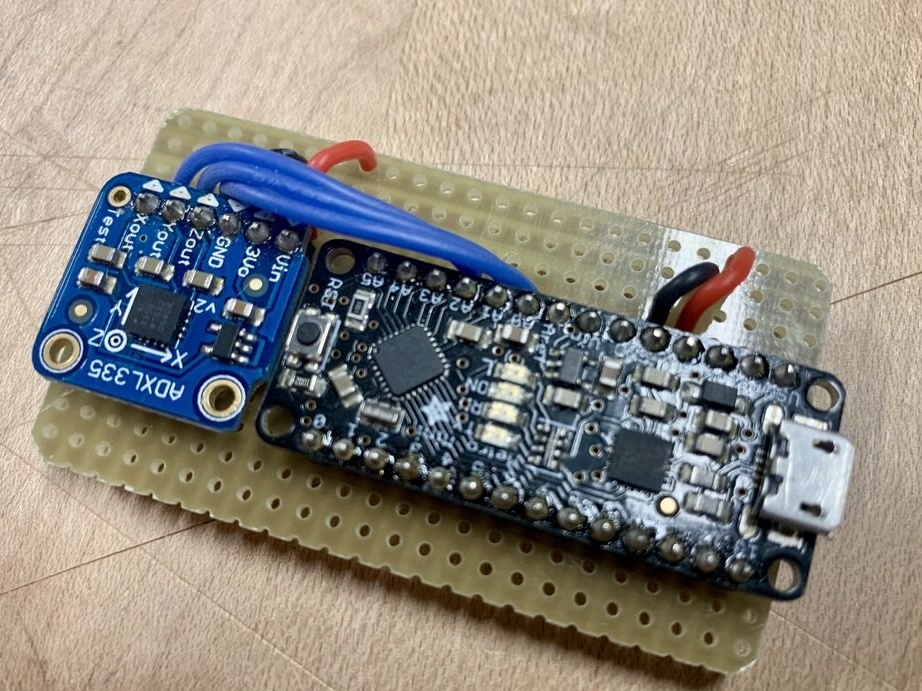
Observing the polarity, it connects the reciprocal part of the JST connector with the plus and common tires of the breadboard:
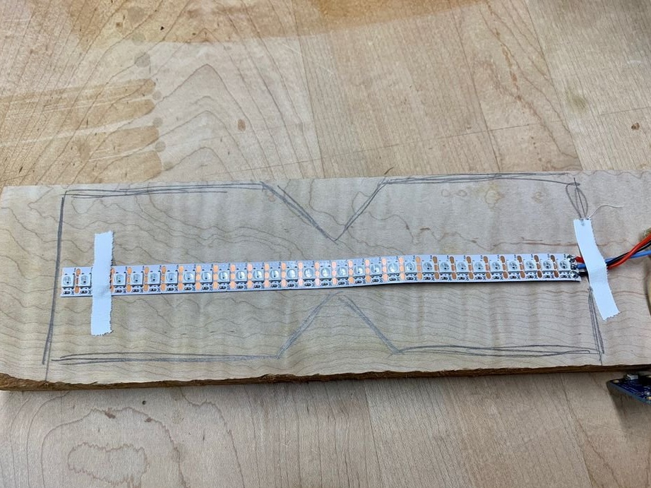
Performs further soldering with the circuit breaker open or the connector disconnected. Connects a piece of tape with addressable LEDs that holds 30 of these diodes. Tape can only be separated in areas specially designed for this purpose. The power wires are connected in the correct polarity to the corresponding layout buses, and the serial data input is connected to the digital output of the Arduino-compatible board selected in the program:
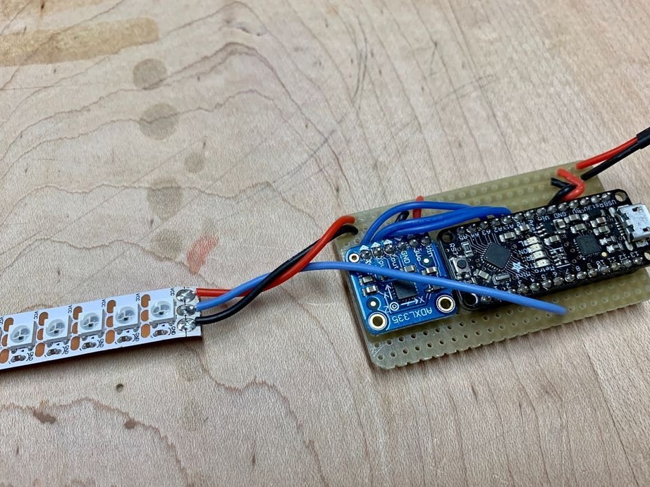
There are arrows on the tape (sending greetings to one of the participants of the resource, which one he will guess), indicating the direction of data transfer from each previous address LED to each subsequent one. Connect a piece of tape so that the data goes away from the board.
After the tape, the wizard takes charge of the touch button. There are three wires again: plus, common and output. How to connect the first two, of course, and the third - to the digital input of the Arduino-compatible board selected in the program. When touched, the button gives a logical unit. Electronics ready:
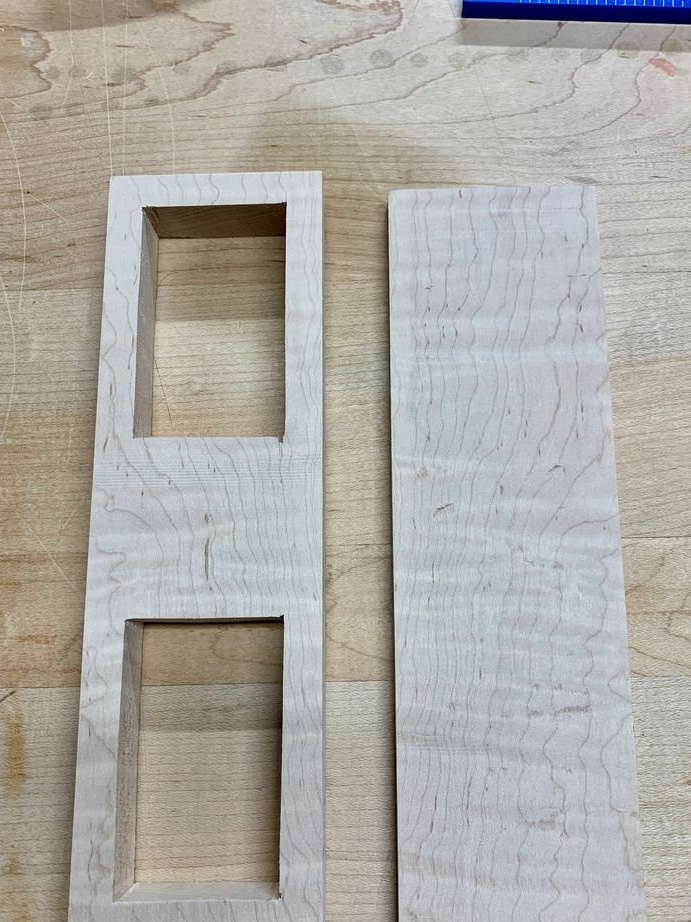
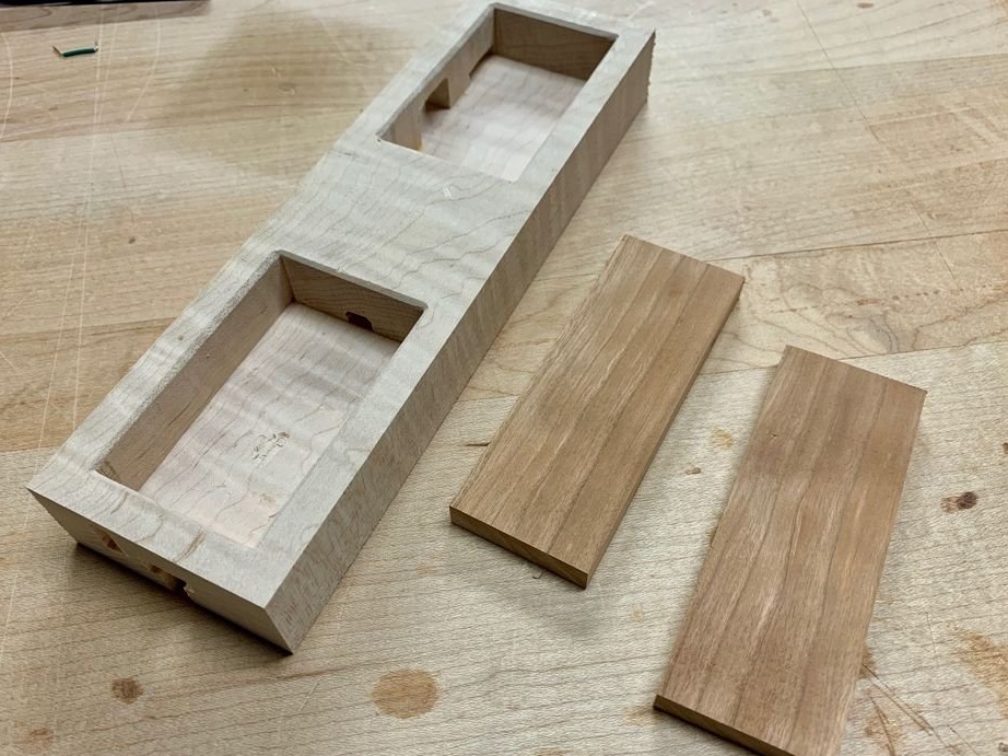
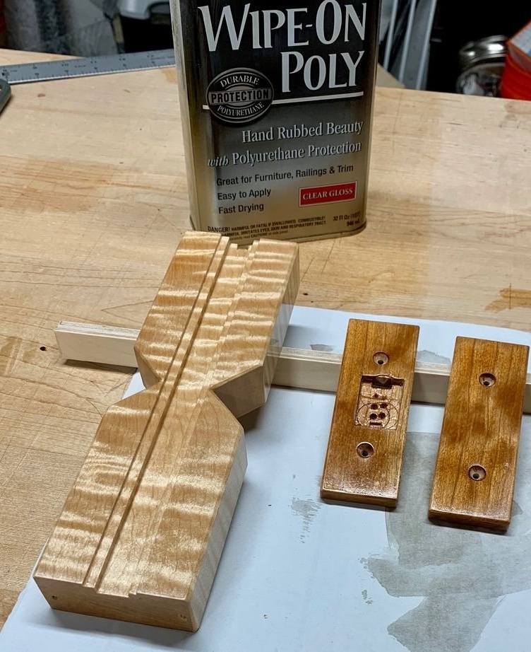
The soldering iron will rest, the jigsaw will work. Immediately after estimating and transferring the hourglass outline to a maple board:
The same thing can be glued from several layers of thin plywood.
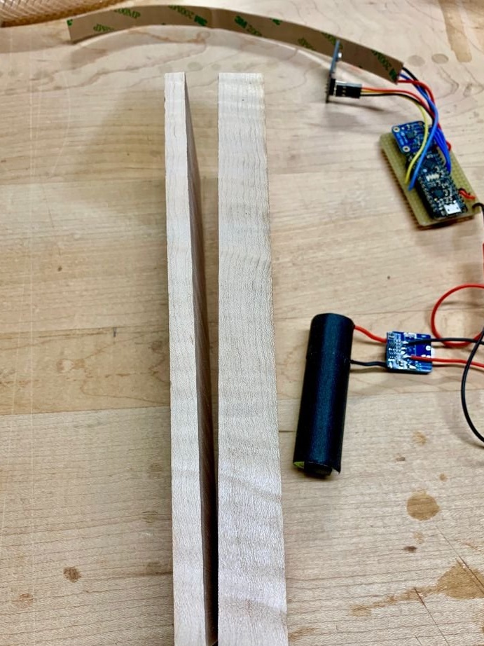
The master takes another plank of the same shape, but thinner, compare from the side:
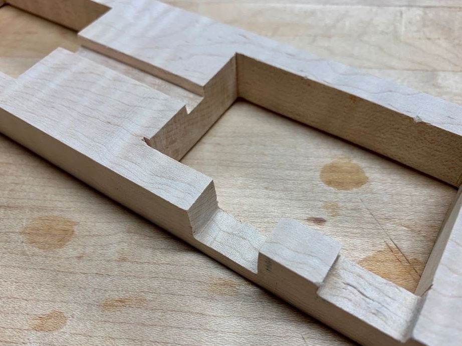
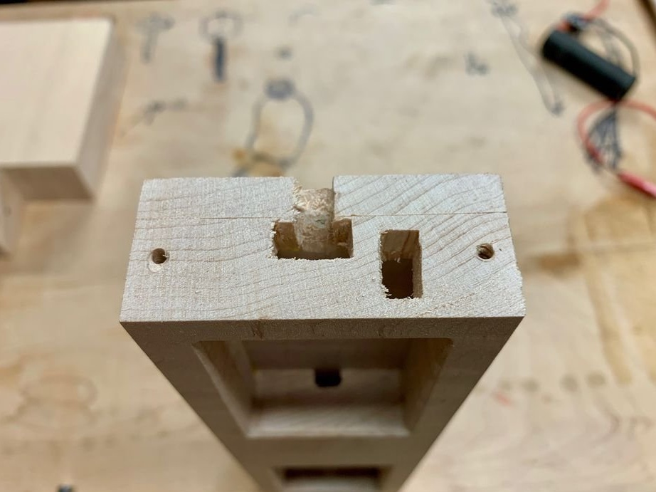
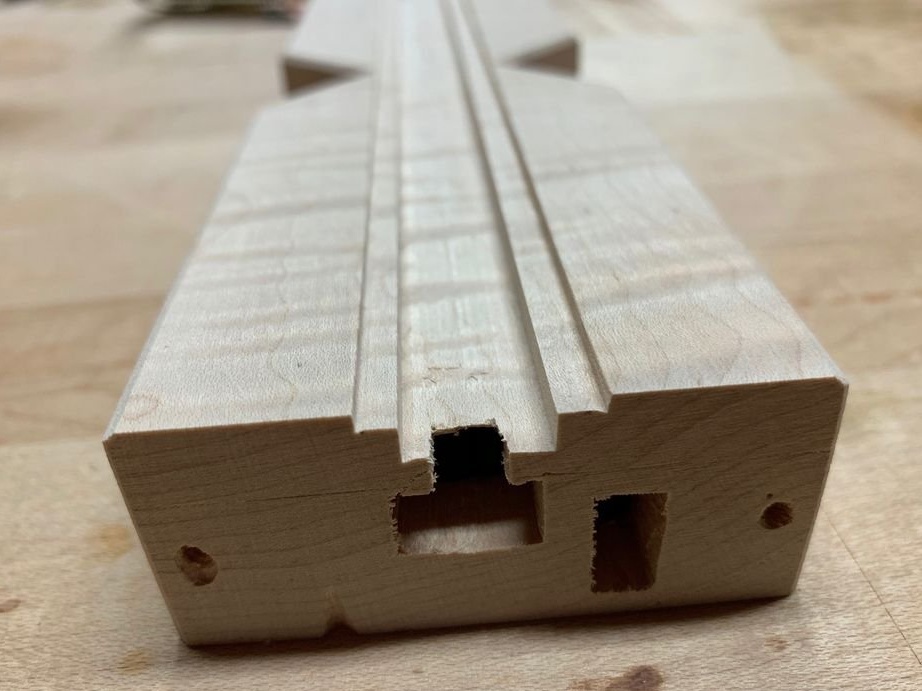
In the plaque, which is thicker, drills holes for the jigsaw blade and makes compartments:
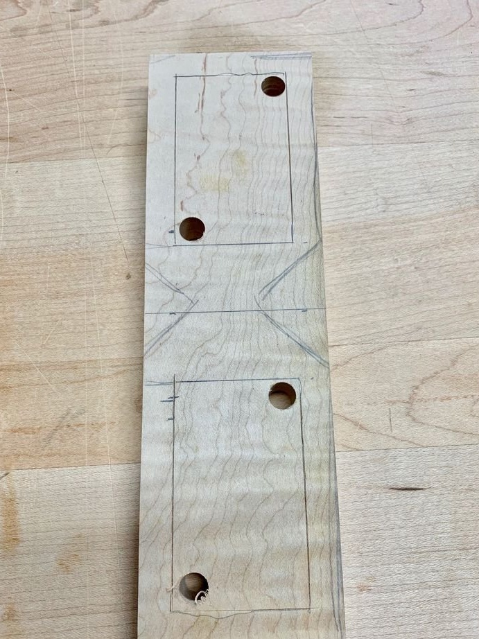
Everything fits:
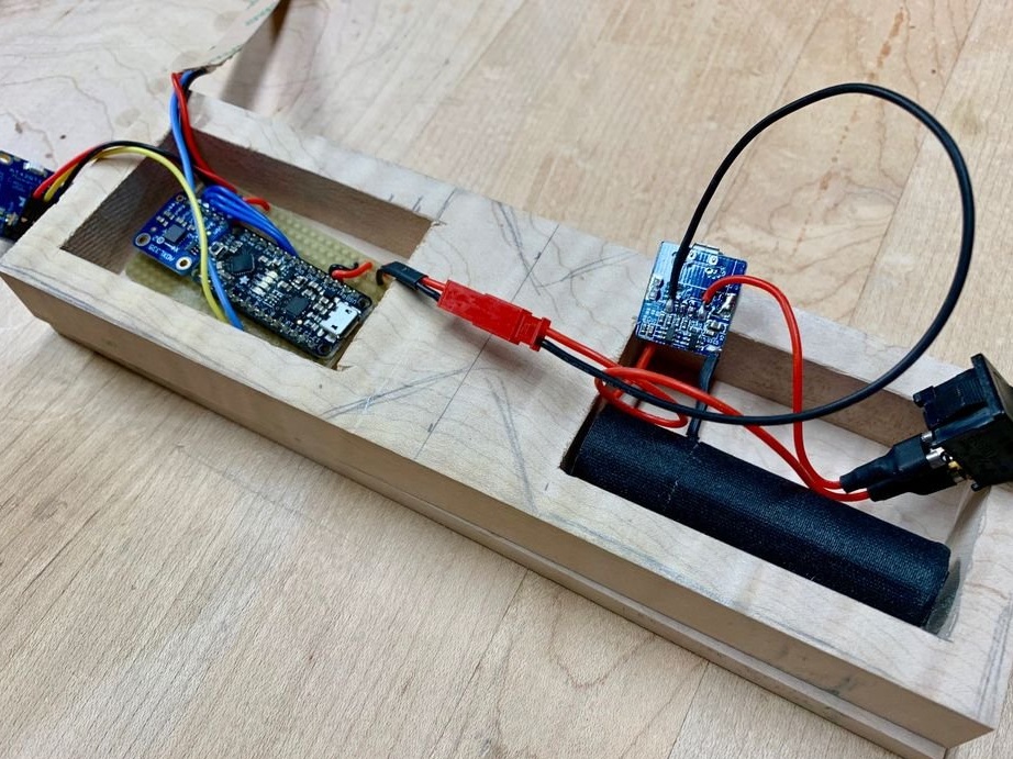
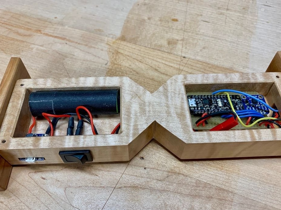
And in these recesses will fit a switch, connector and wires connecting the compartments to each other:
Like this:
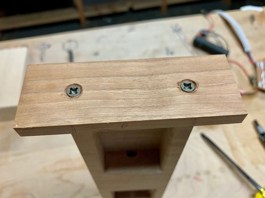
Glues the boards, and the bottom appears at the compartments, next to it are ready, but not yet installed stands:
You can stick it, you can screw it with screws, as you like:
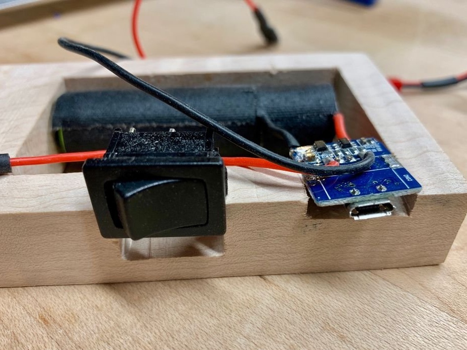
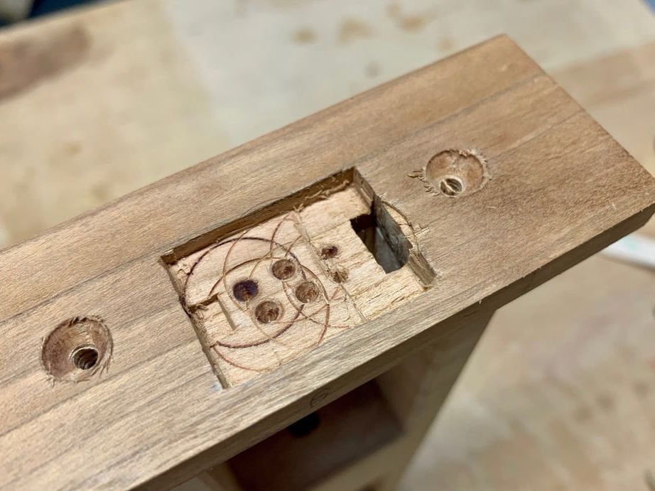
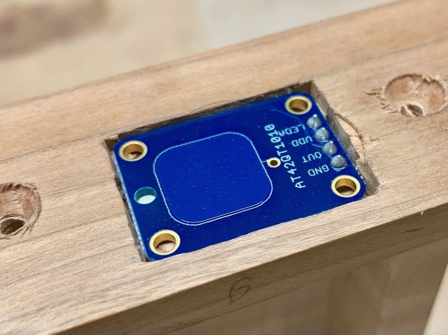
In this recess, a touch button will fit in the stand:
Here it is in place:
In the case itself, thatguyer makes recesses and holes for the wires to the tape and touch button:
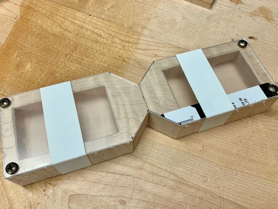
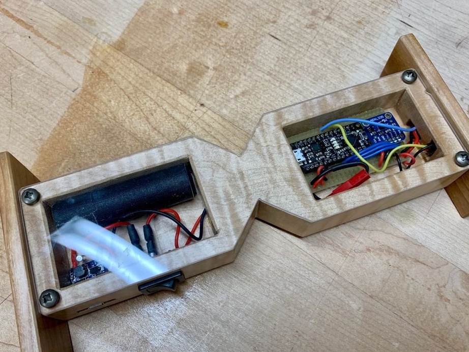
The plexiglass covers the compartments at the back so that the electronic part does not fall out:
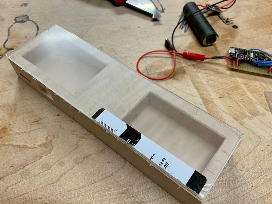
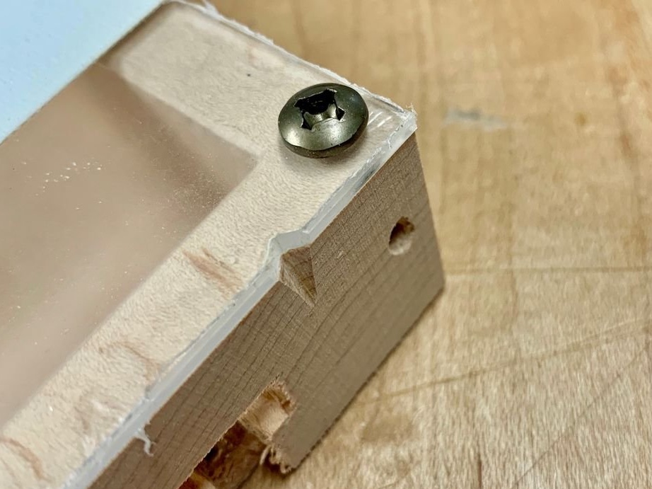
Having fixed the plexiglass with tape so that it does not move, drill and fix it like this:
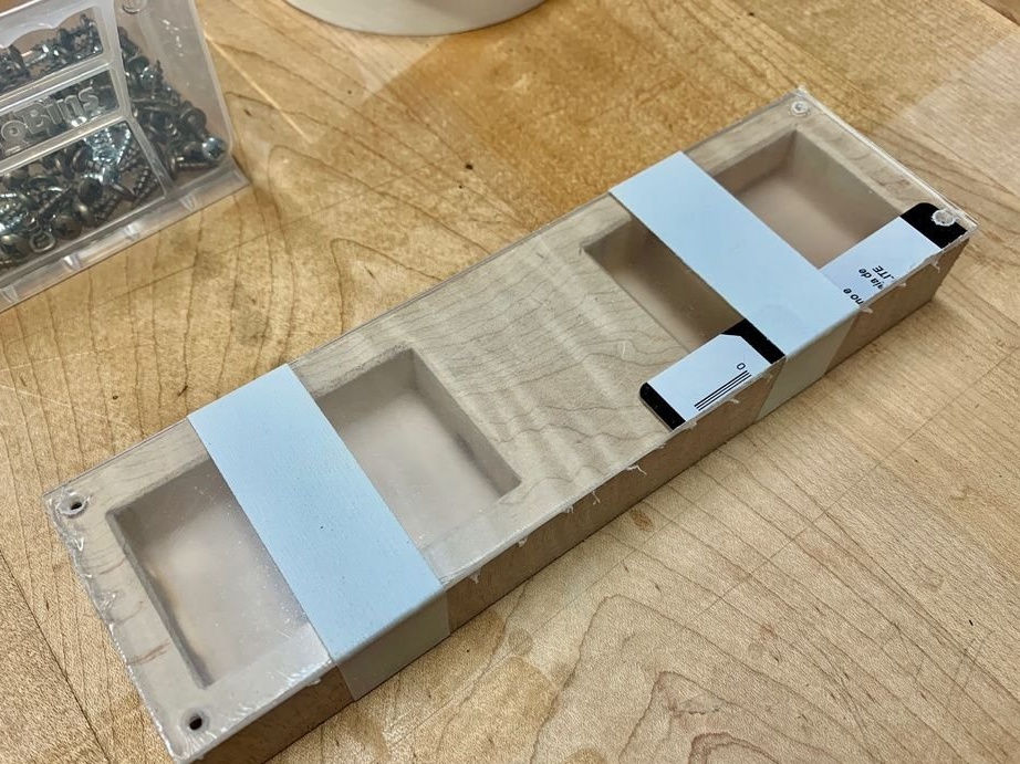
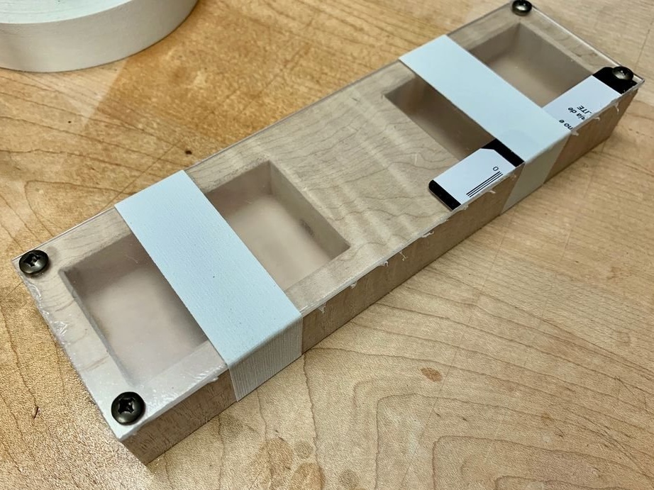
Makes marks for the convenience of combining plexiglass with a tree so that there is no situation: damn it, the holes do not match, but you just need to turn the lid over:
Joining everything together, sawing along a marked outline, getting the shape of an hourglass:
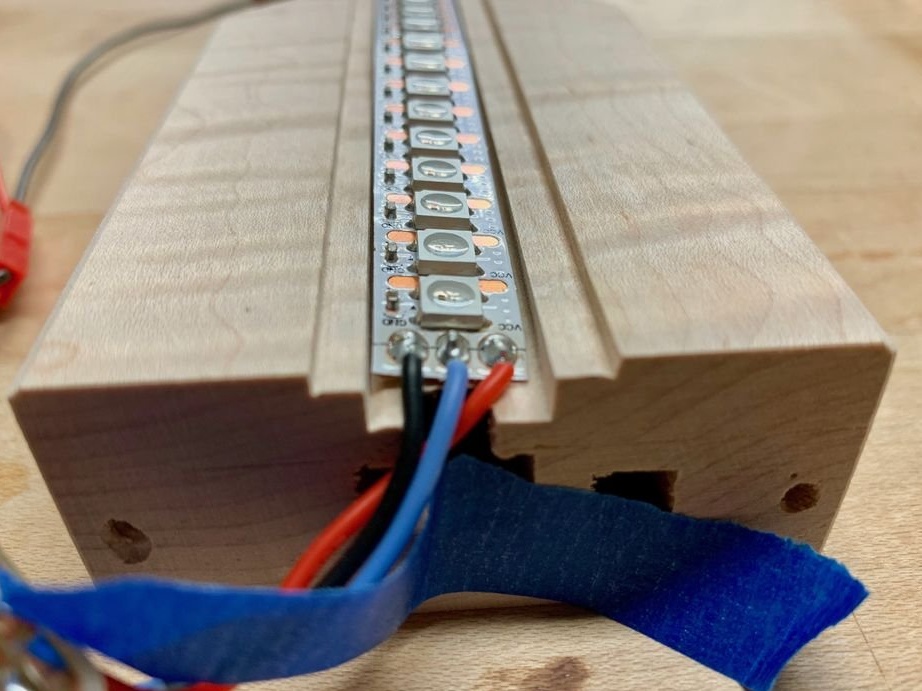
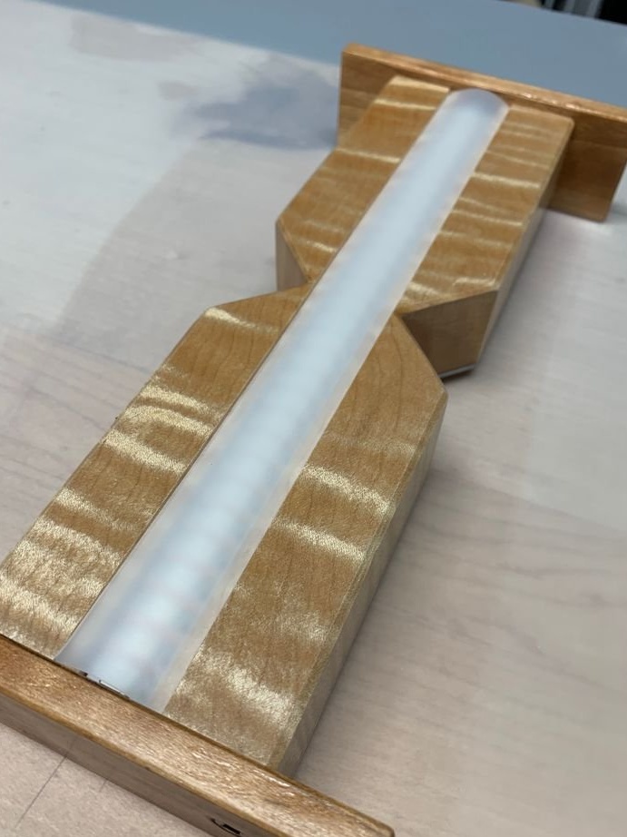
On the side where there are no compartments and plexiglass, it makes a recess for the LED strip:
What you need!
It disassembles the case, polishes it and covers everything wooden with two layers of shellac. Again, it polishes slightly, covers it with polyurethane varnish, processes it a little with steel wool, and it turns out ...
Returns electronics back:
Then plexiglass:
It covers the LEDs with a matte filter:
Floods firmware, she will need a library Fastled. In the text before filling in, it is necessary to indicate which of the conclusions what is connected, as well as how many LEDs in a piece of tape.
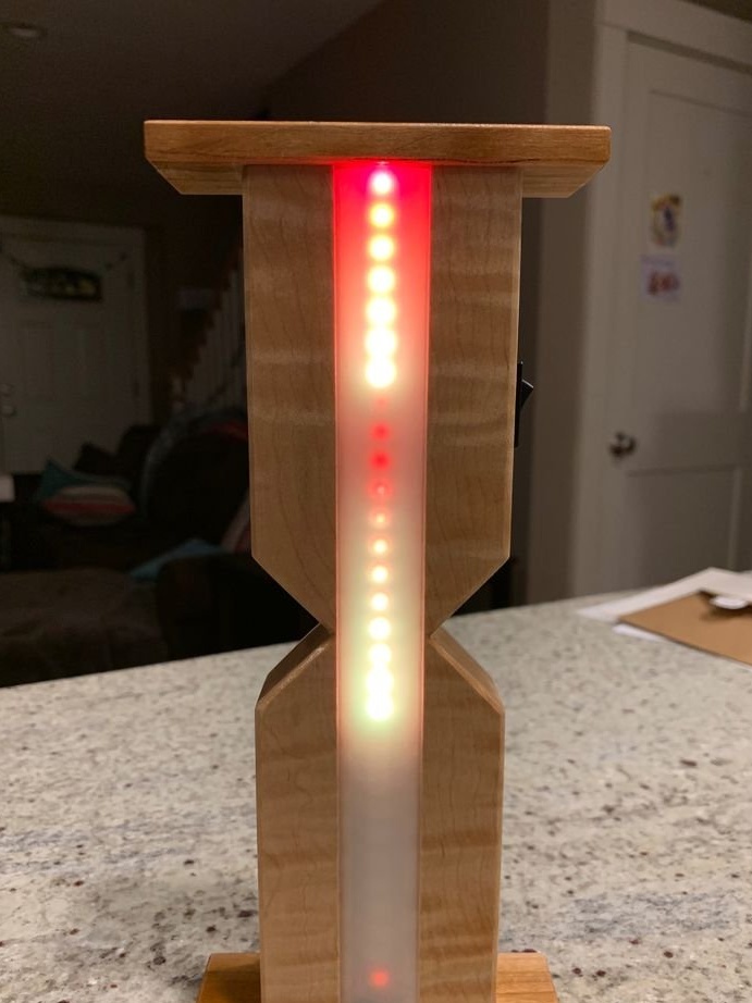
Switching the operating modes of the watch occurs when their position changes. With the sensor up - setting, with the sensor down - counting down, sideways - pause. When entering the setup mode, a yellow flashing cursor appears, each touch of the sensor adds one lilac division corresponding to 15 seconds. If you dial 60 seconds, subsequent divisions will be blue and the corresponding minutes. Every fifth minute division is marked with a different color for convenience. In the countdown and pause modes, the clock behaves similarly to a real sand.
Repeating homemade work, you can connect a piezoelectric or dynamic head (one through an amplifier) to one of the digital inputs and add sound effects to the firmware.