
Today, together with the author of the YouTube channel AlexGyver, we will try to make a cool LED lamp that is as simple as possible, but very effective.
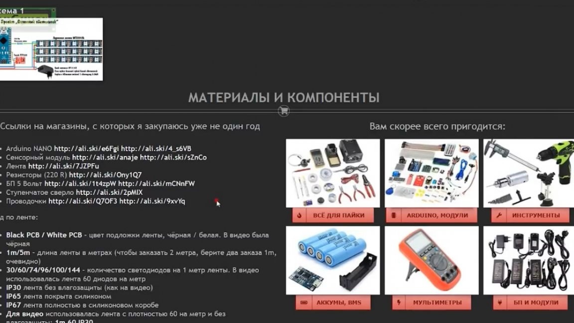
In general, the idea is very simple. We take the address LED strip, arduino, which will control it and the touch button.
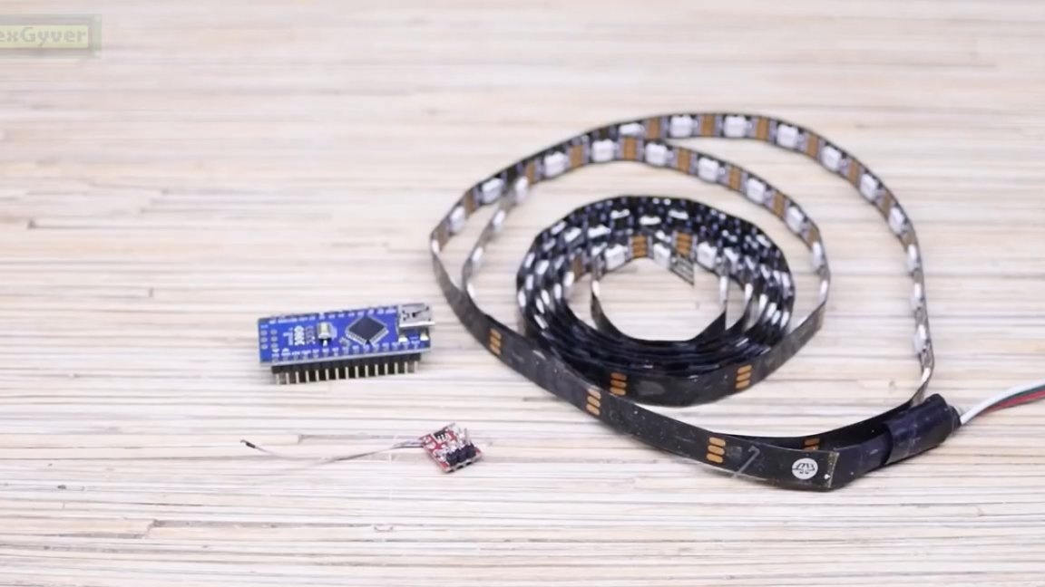
Saw it all according to an extremely simple connection scheme and get a tape with effects and control with one button.

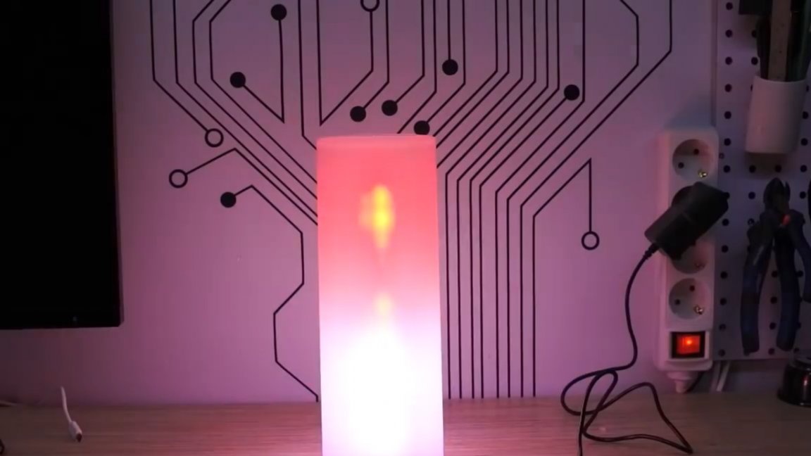
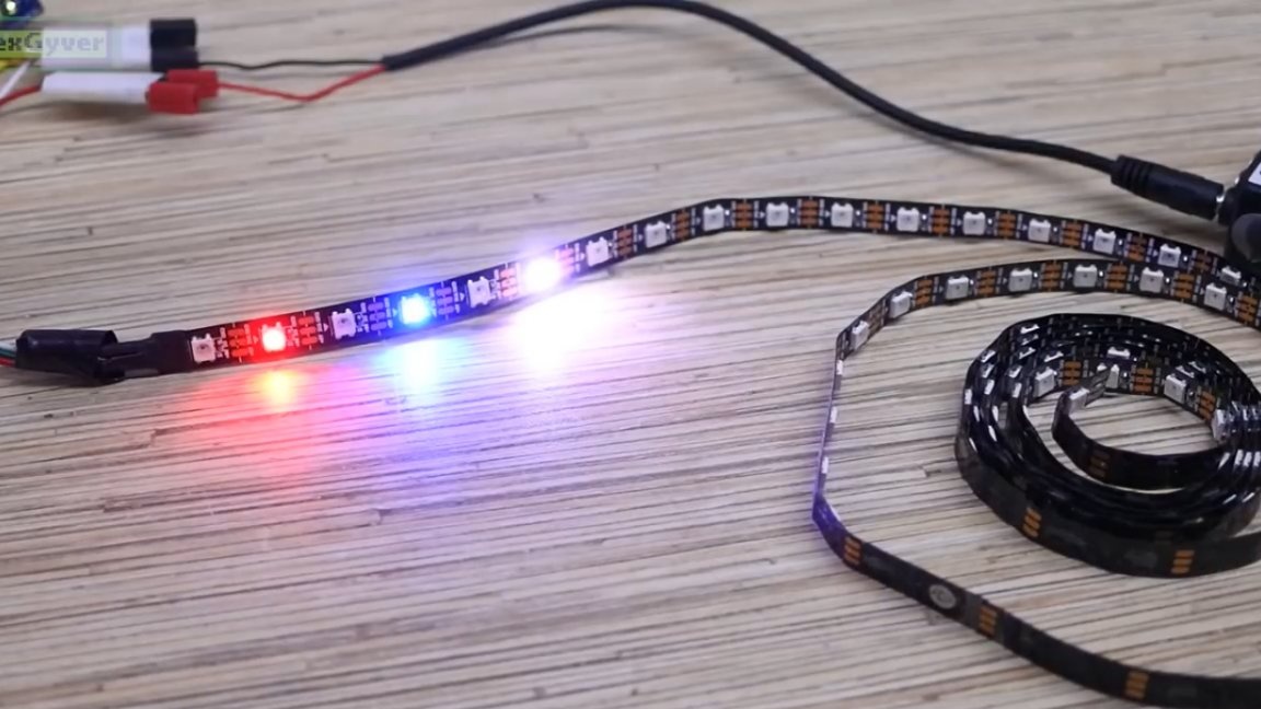
We put all this into a translucent vase and get a night lamp, an element of the interior and just a very entertaining thing. The fact is that we will use address LEDs that can be turned on in any color independently of each other.
The thing is complex, controlled by a microcontroller. All components for this homemade product can be bought on aliexpress, you will find links to.
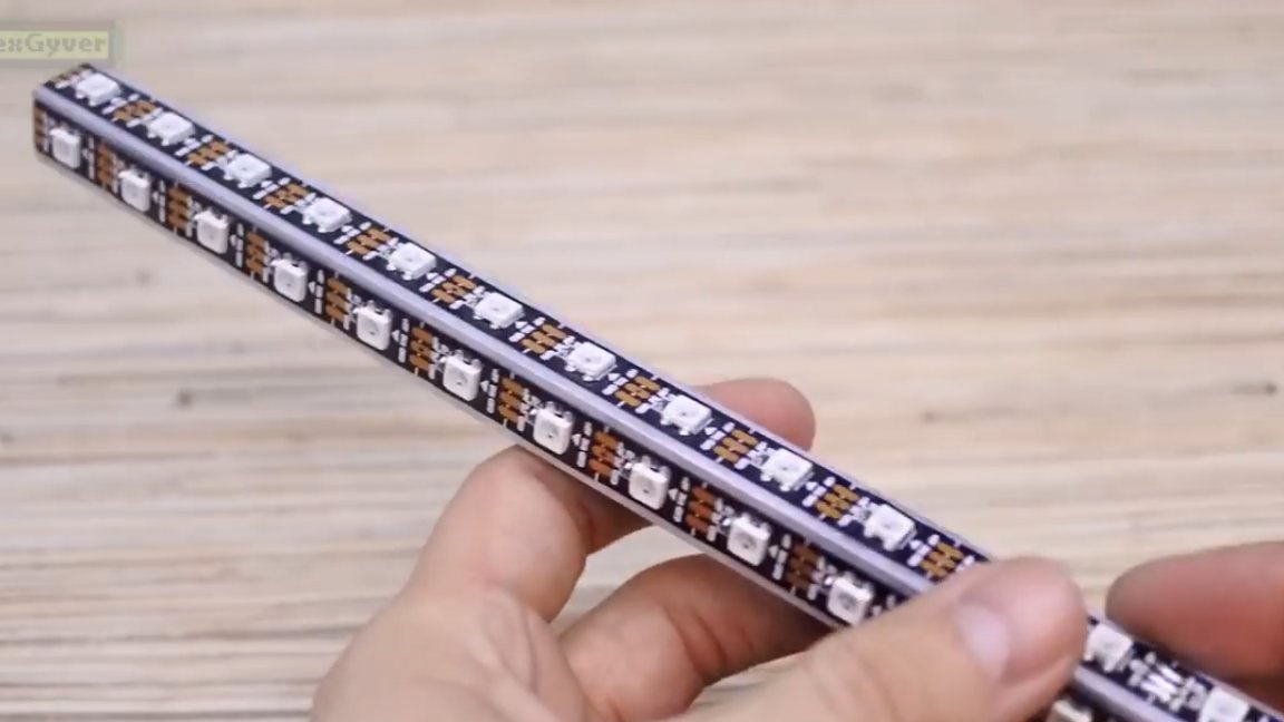
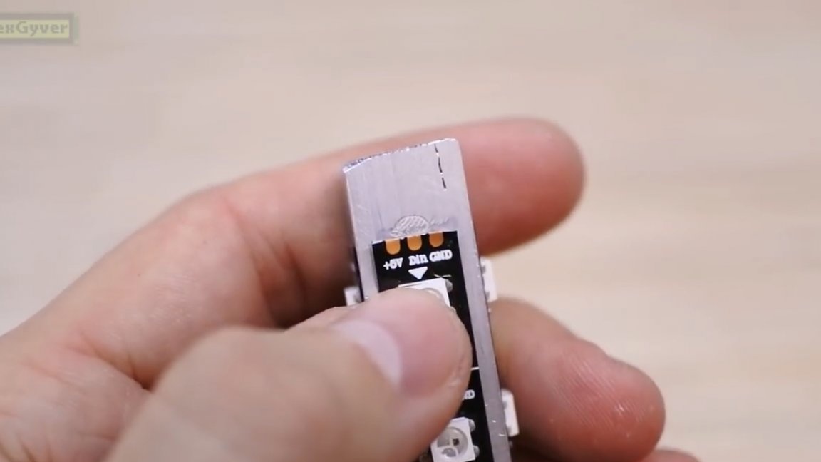
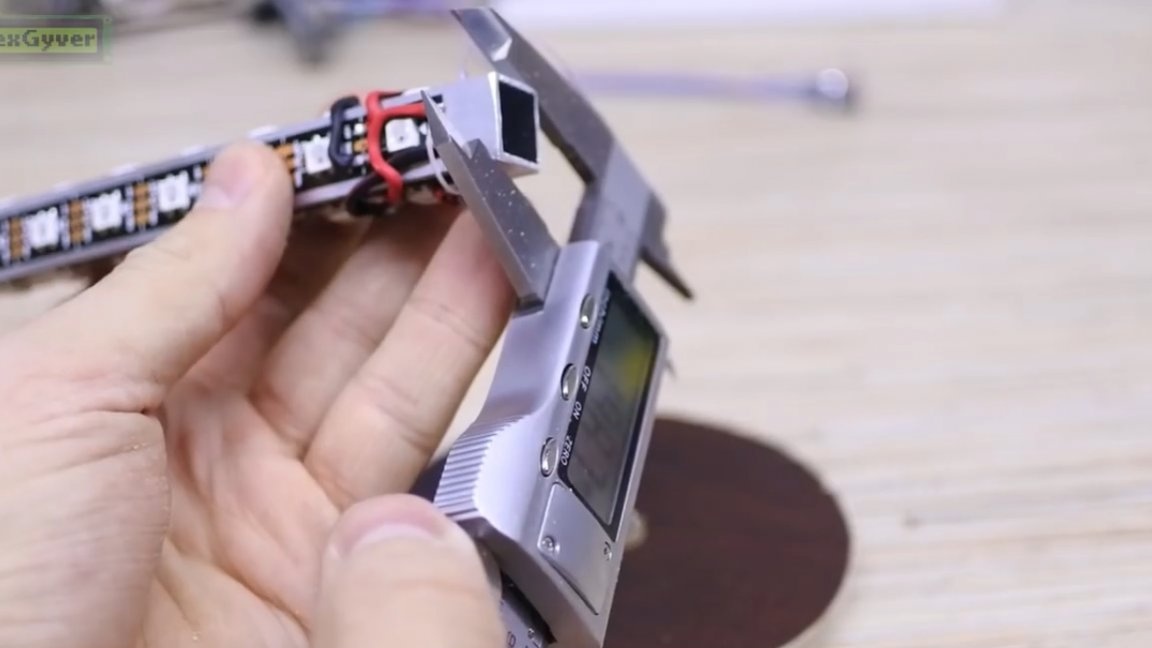
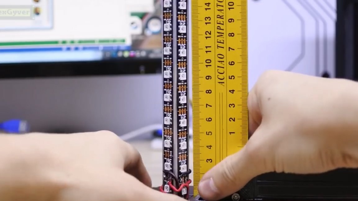
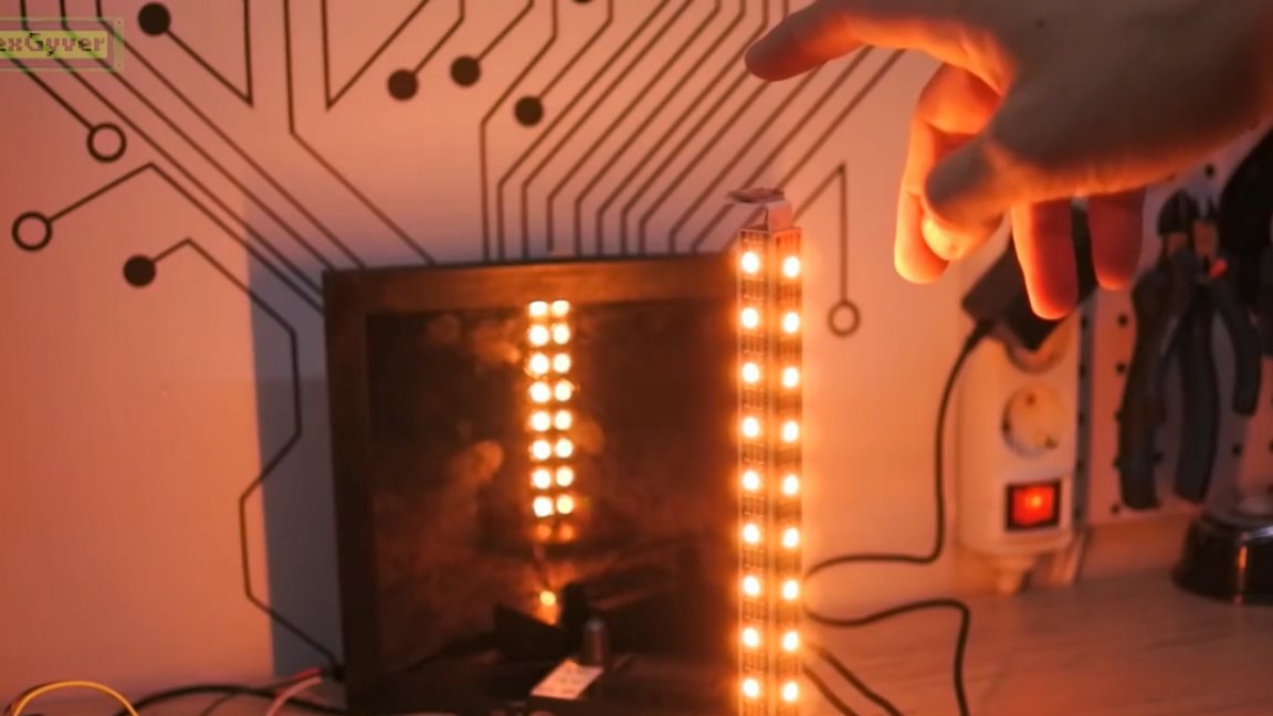
There will be several segments of tape in the lamp so that it shines in all directions. We take 4 segments, because they are remarkably mounted on a square aluminum profile, which at the same time will remove heat, since the tape is heated.
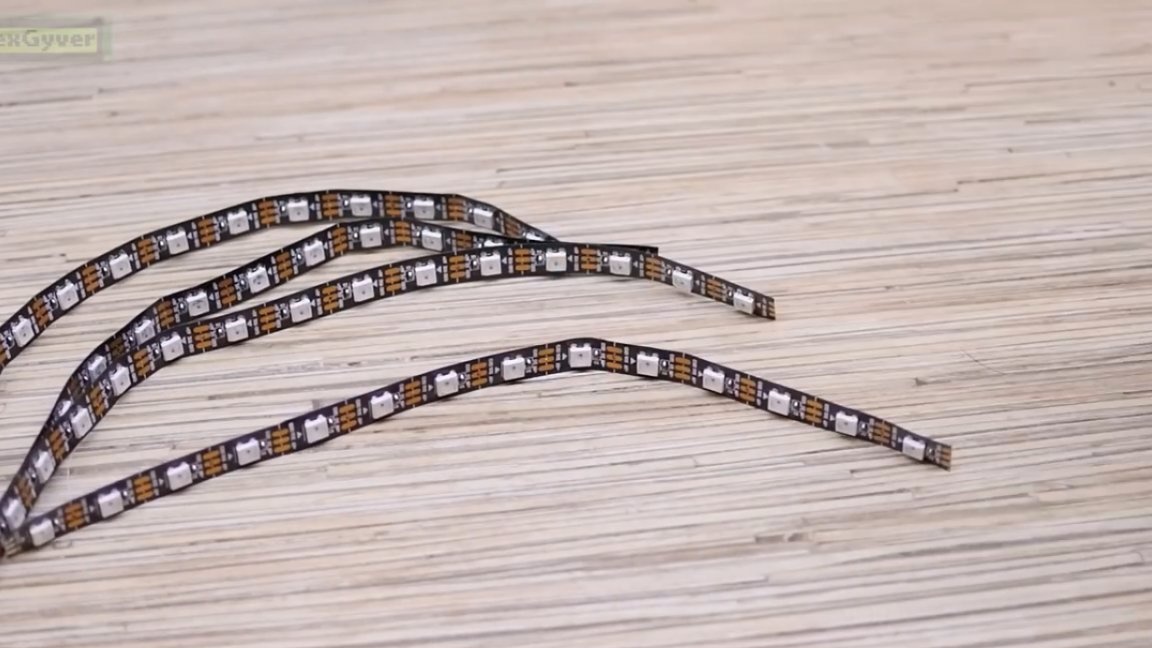
In this design, the heat sink is certainly doubtful, but it is still better than gluing the tape to another material. Here's the thing:
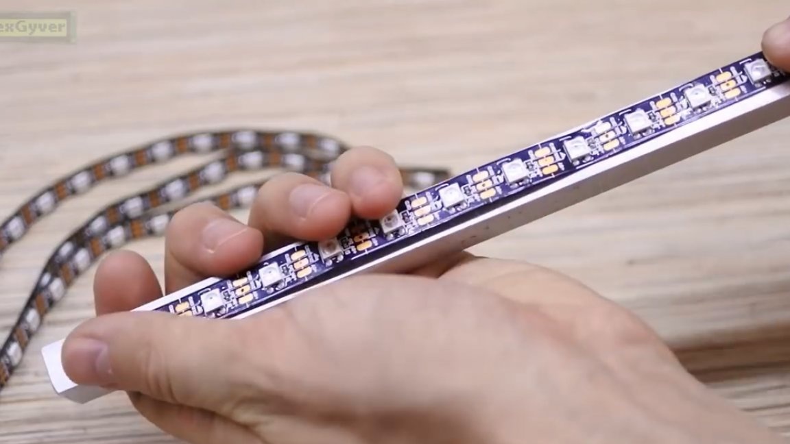
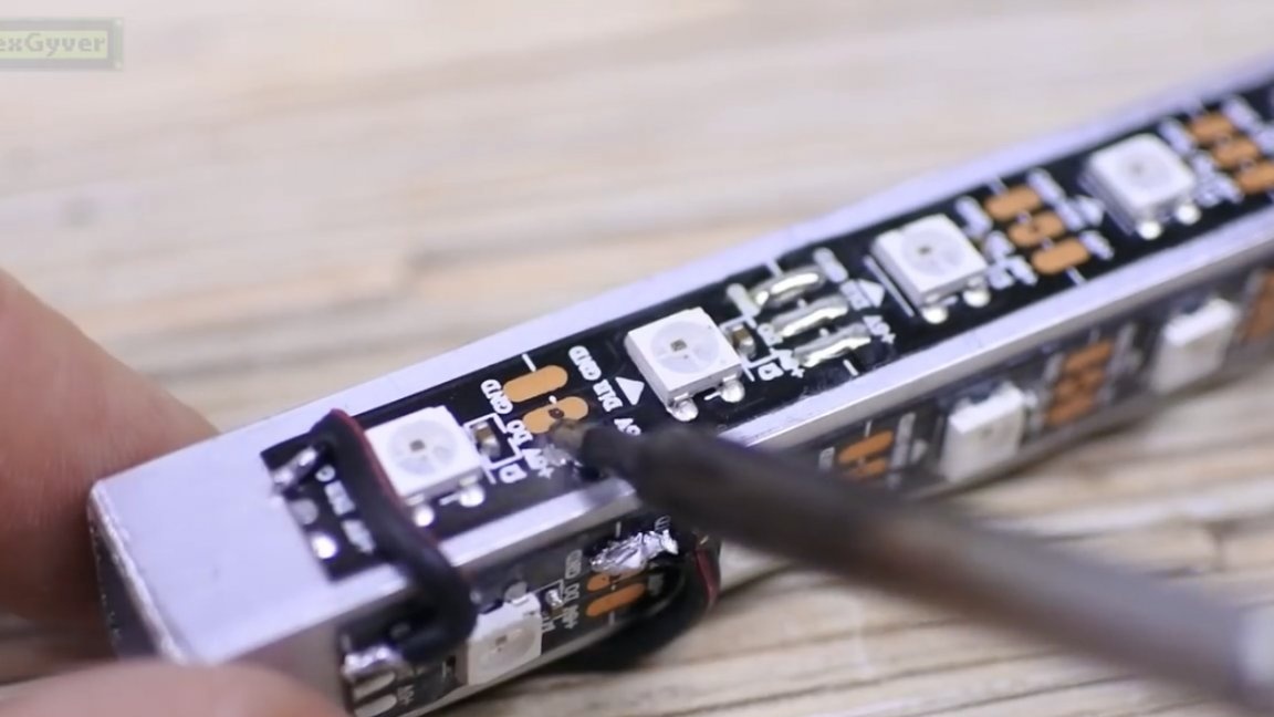
An important point! All pieces must be glued so that the Din contact is on one edge of the profile, and from the one that we leave 1 cm without tape for fastening.
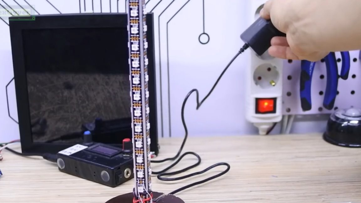
You need to power the system from a powerful 5V power supply.
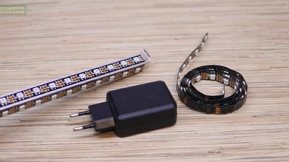
The more LEDs there are, the more current margin needs to be made. 1 LED in maximum bright white mode consumes 60 mA. If you need such a bright white mode, then calculate the power supply you need, if not, then enough for the smartphone charger 2A. For all color modes, this will be more than enough.
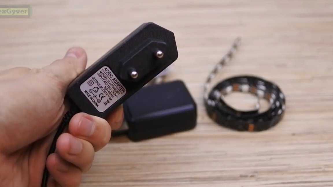
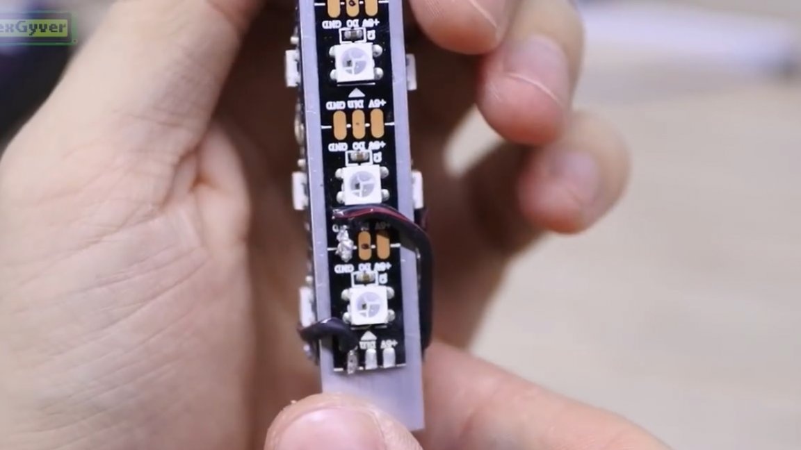
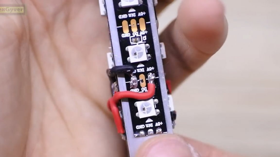
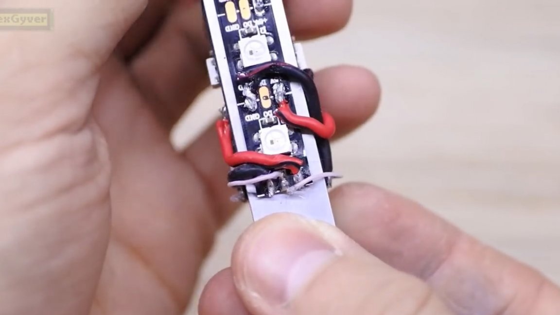
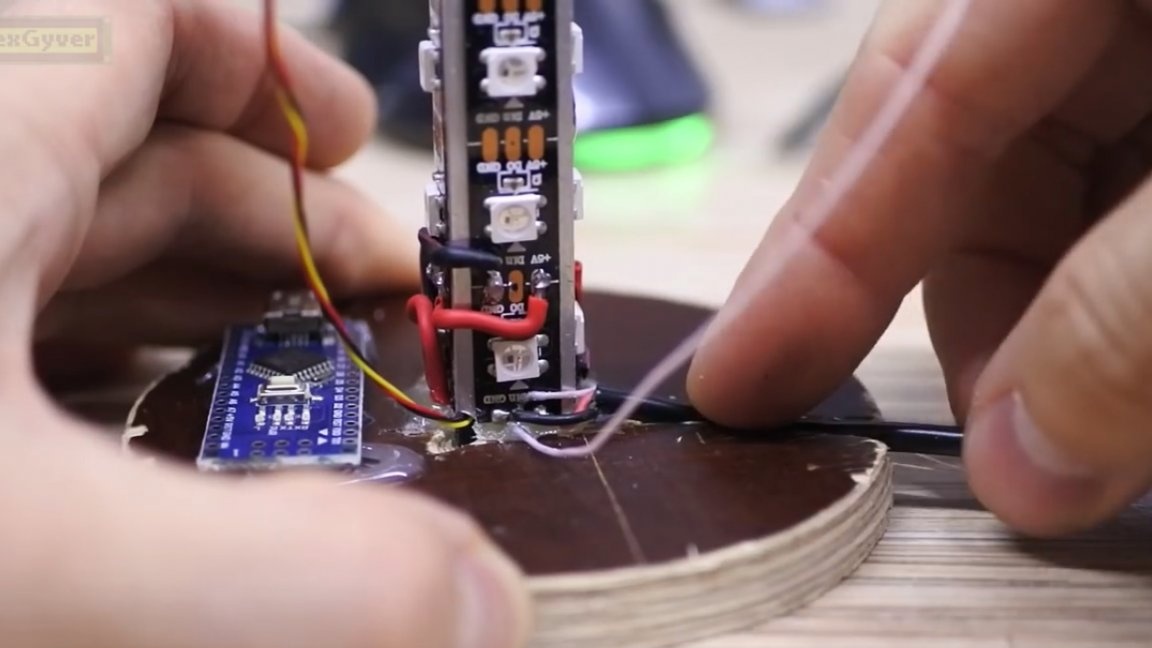
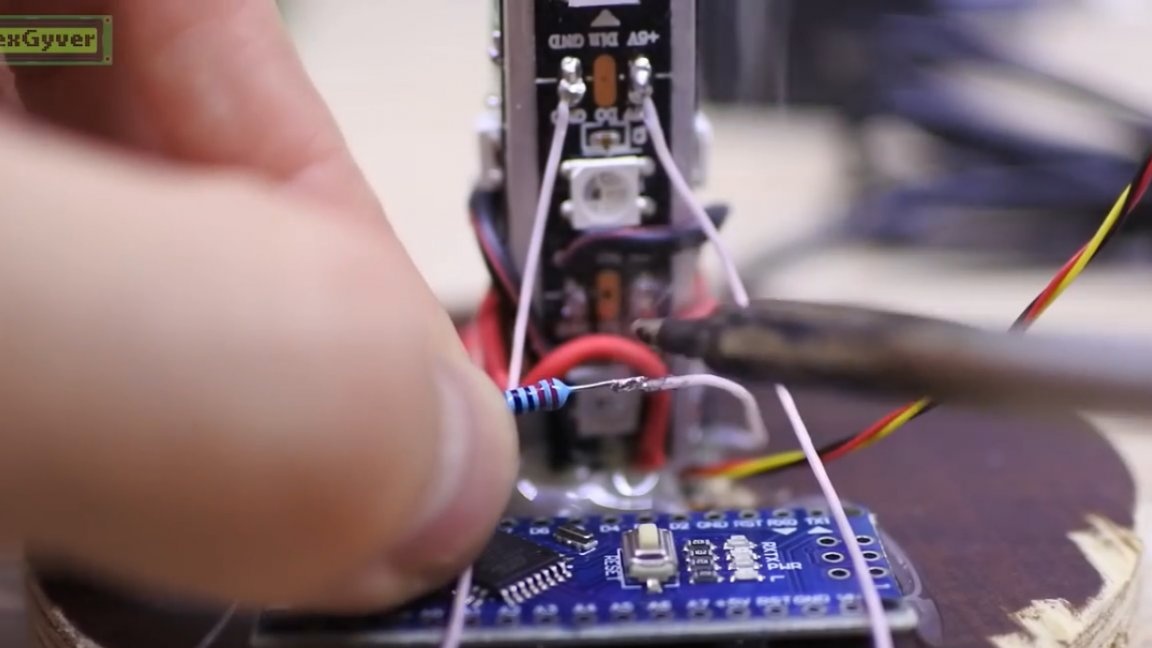
Well, we will use a 2-ampere power supply for 4 pieces of tape with 14 LEDs each. We begin to connect pieces of tape parallel to each other. We connect the GND contacts with thick wires first. Where to solder is not important, because the tape is parallel to itself. We do the same with the 5V pin.
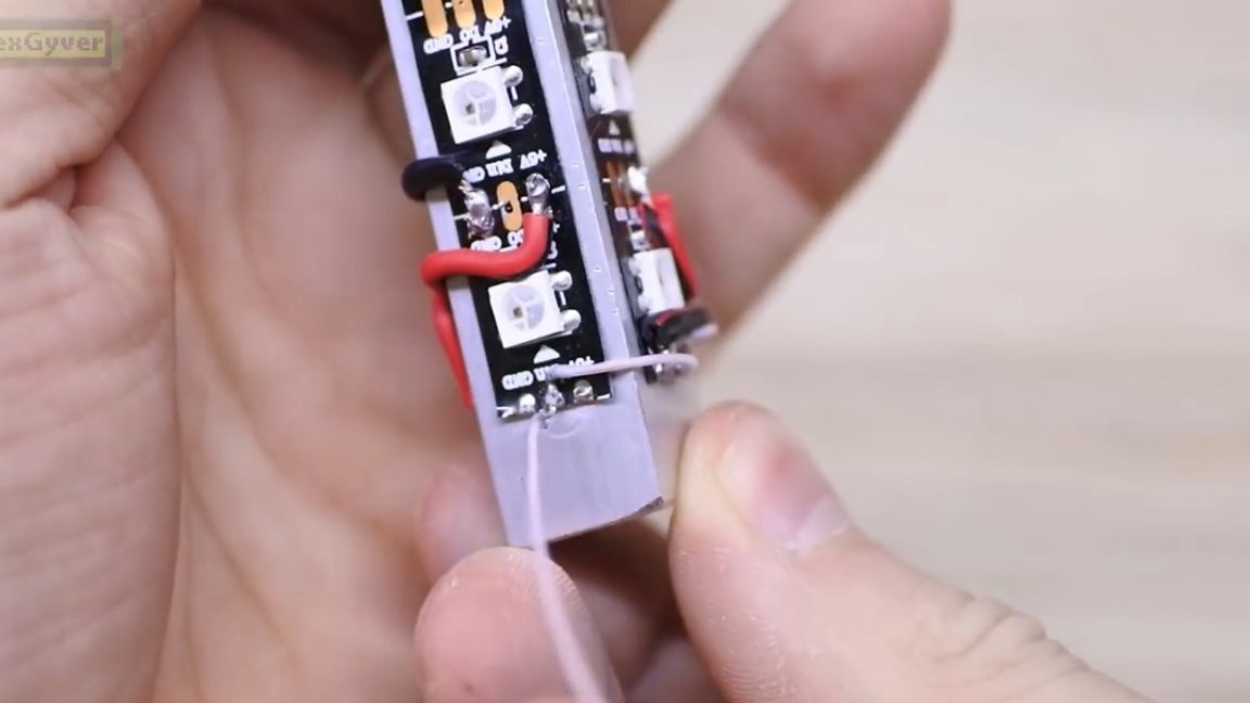
And it is no longer necessary to connect the Din contacts with a thick wire.
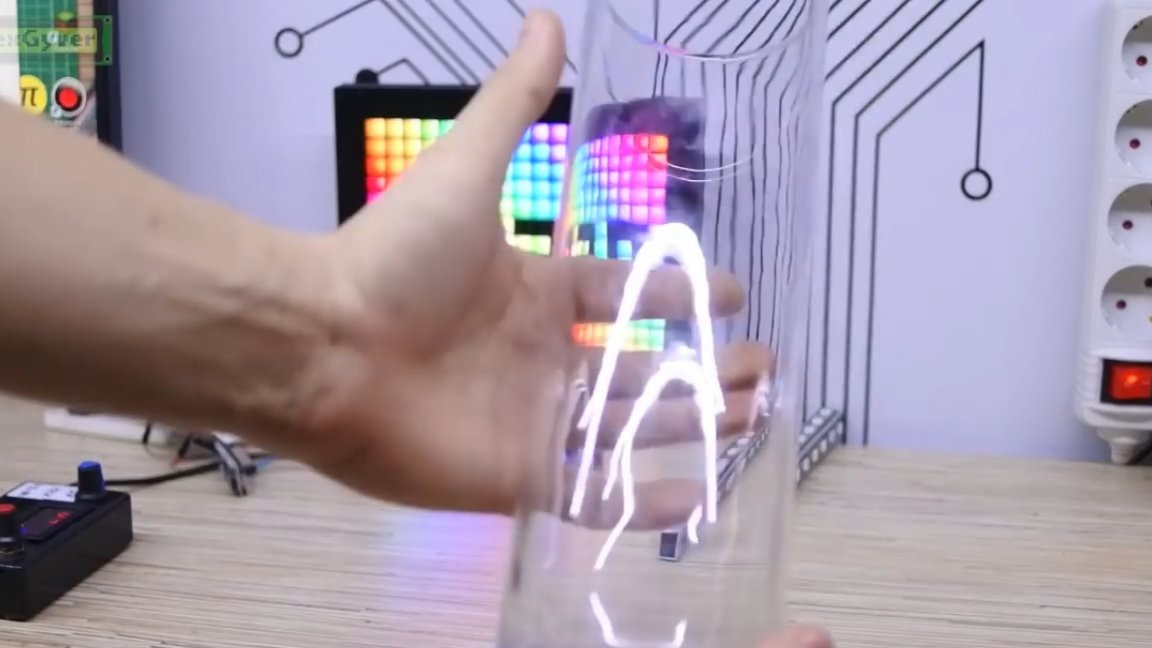
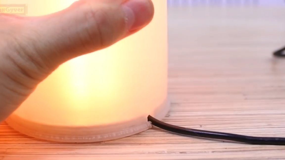
Now the most difficult thing is to find the case. Today we need a matte cylinder, for example, a matte flower vase.

The author went around all the local shops and, unfortunately, found only a transparent vase, with a matte it would be generally cool.
Well, in general, the author decided to use just such a plastic matte vase for a toilet brush, nothing could be better found.
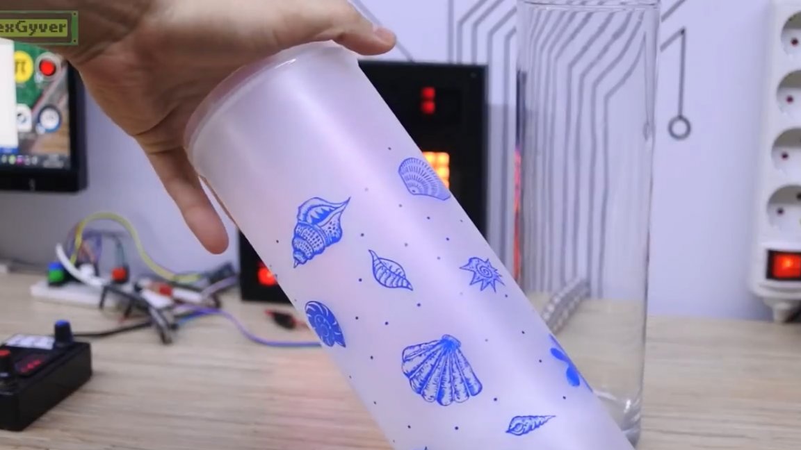
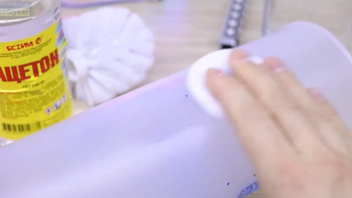
Fortunately, these pictures are erased with acetone.
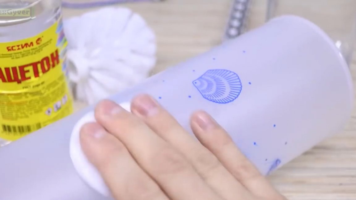
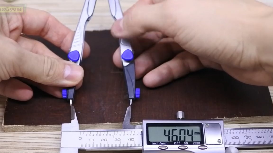
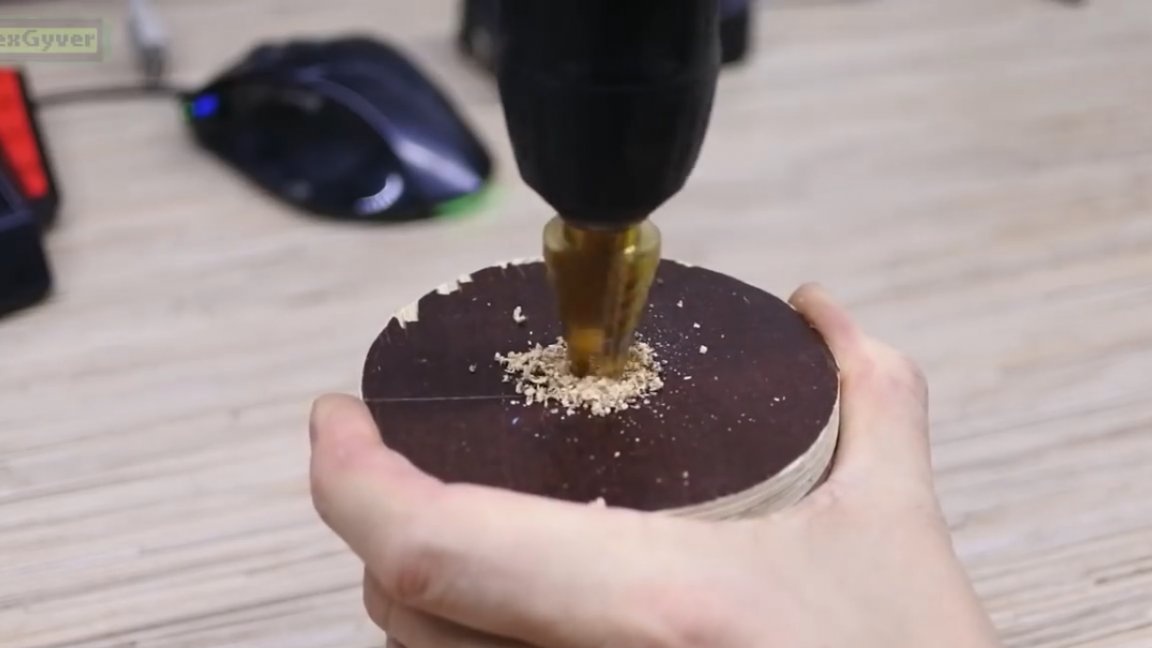
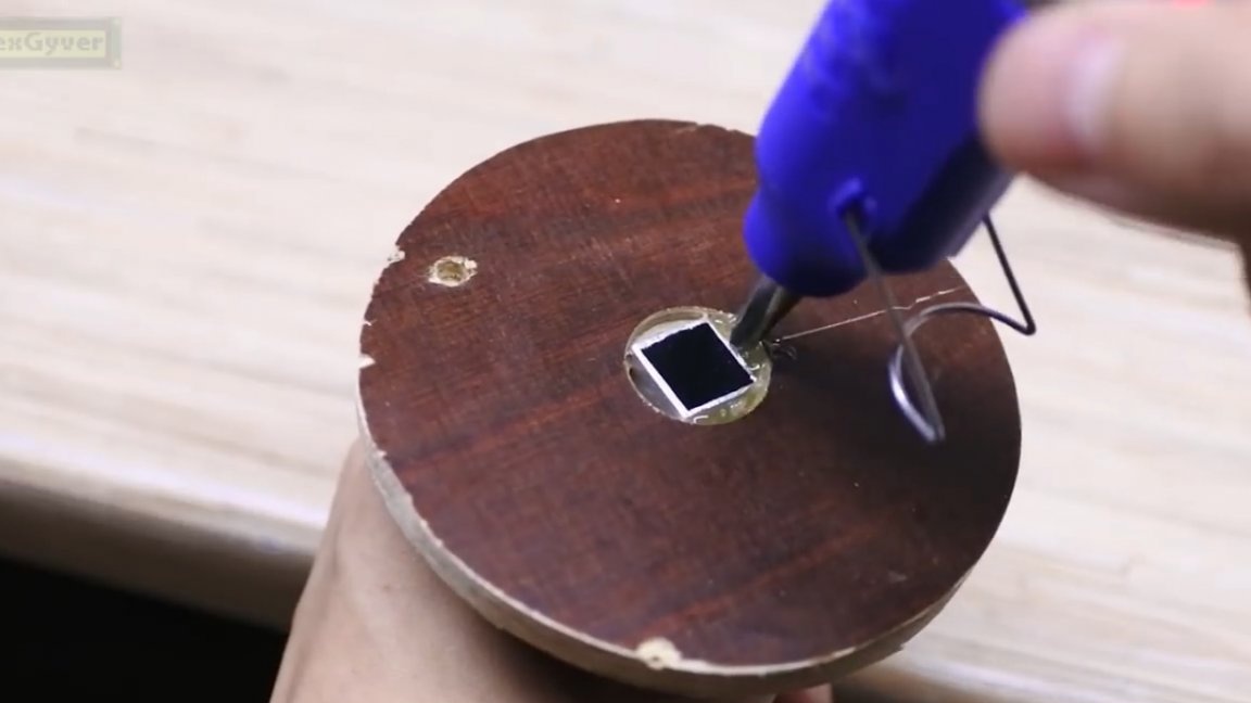
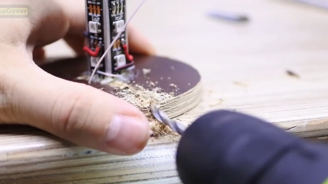
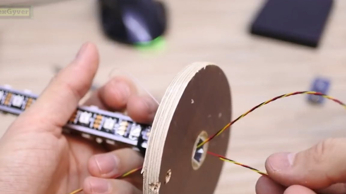
Also, for better dispersion, I had to work a little with the skin from the inside. To fix the diode column inside the vase, we use a piece of plywood. You will need to cut a circle with a diameter like the top of the vase.

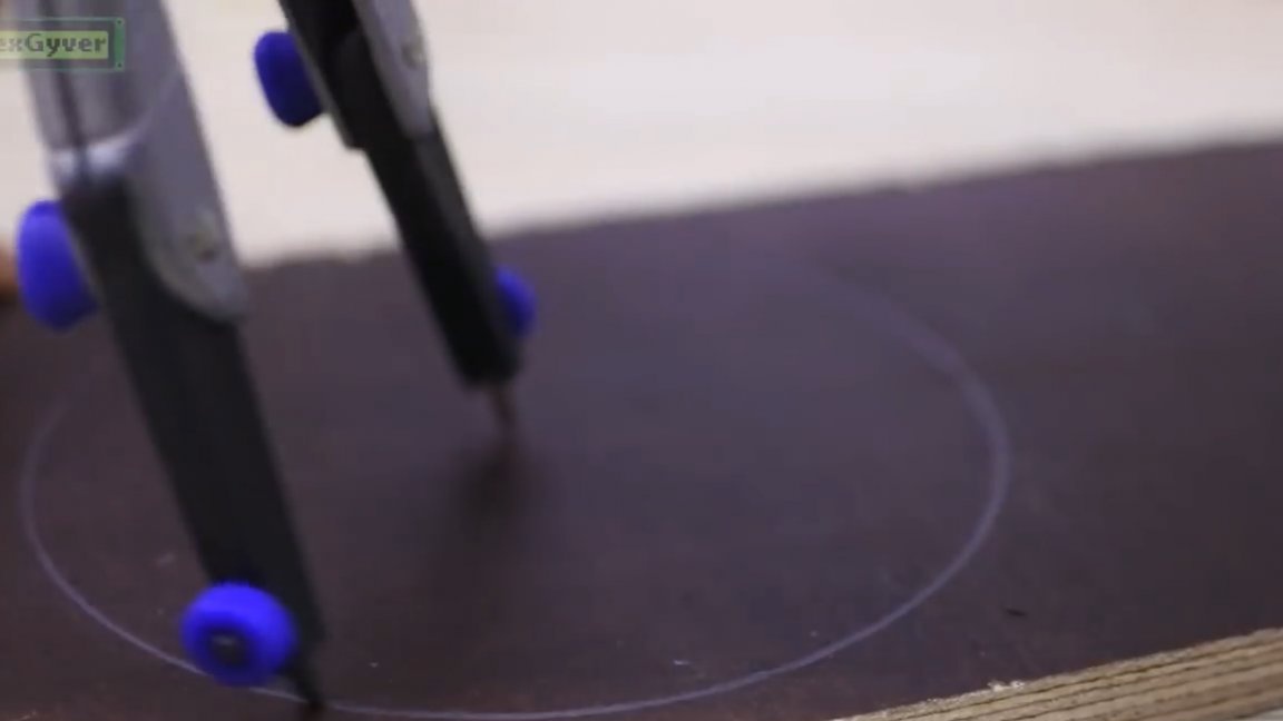

Next, we clamp this thing into a drill and make a circle as coaxial as possible with the hole.
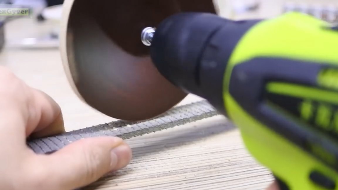
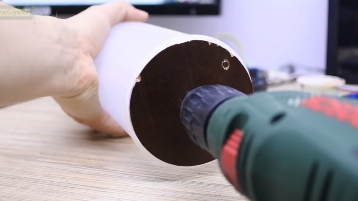
The profile doesn’t fit into the hole, you’ll have to make a bigger hole, for this a Chinese step drill will do.
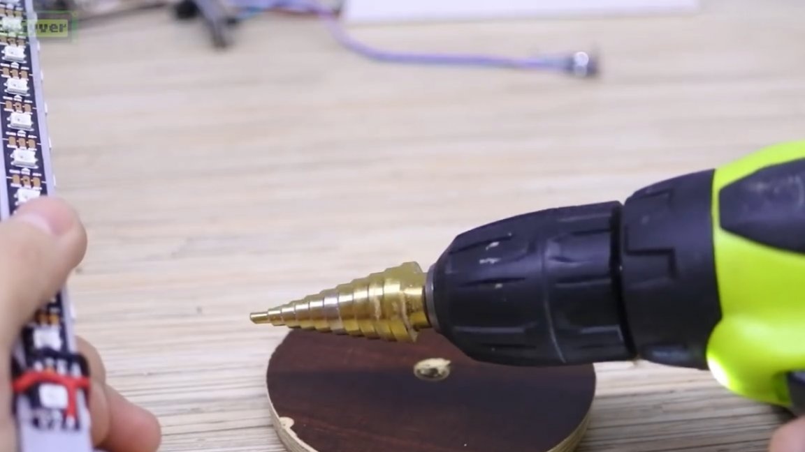
We make the hole a little smaller than the diagonal of the profile so that this profile can be pounded there.
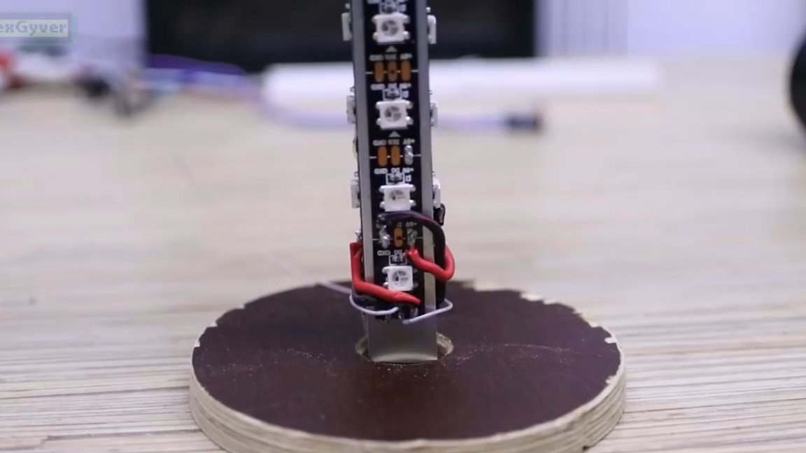
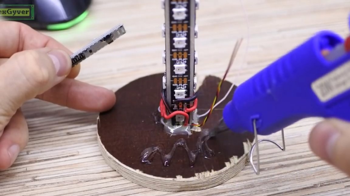
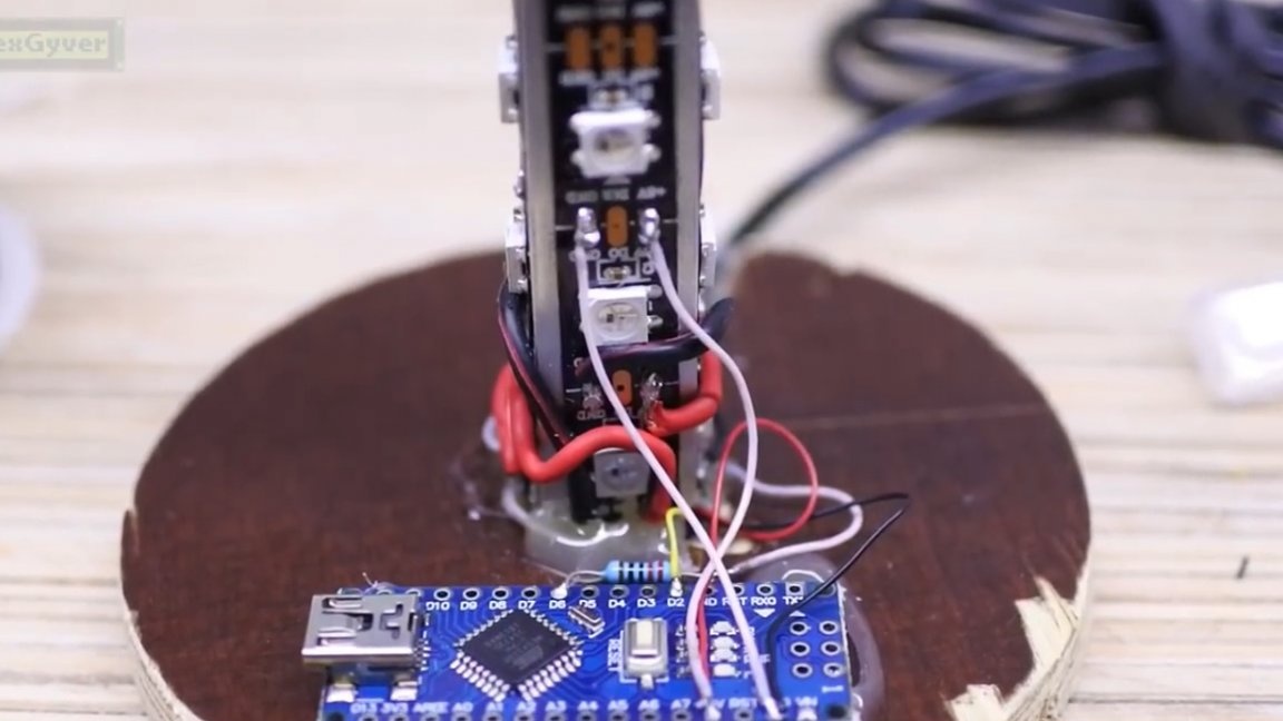
Next, carefully align and fill with cold welding or hot glue, it will be more than enough.
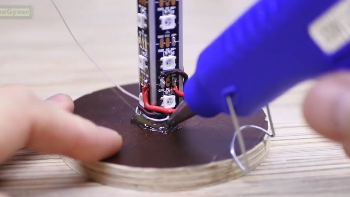
The sensor wire can be run inside the pipe, but this is not necessary. The wire for the power supply will also be set diagonally.
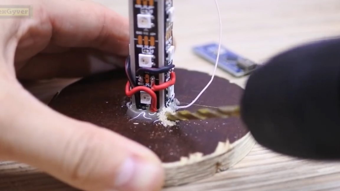
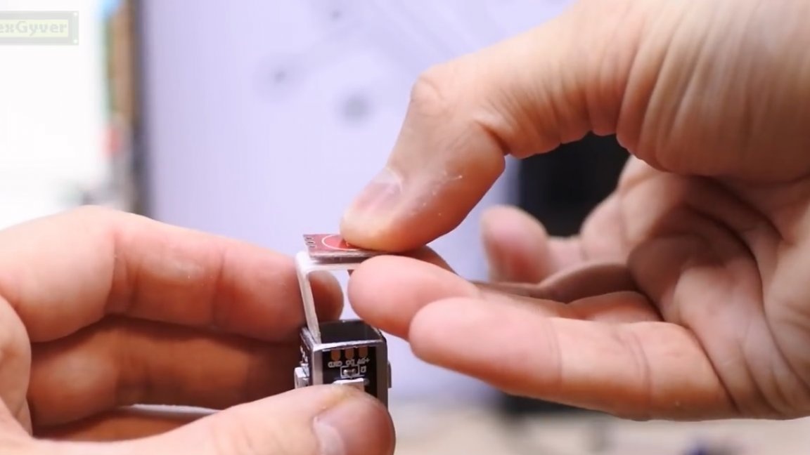
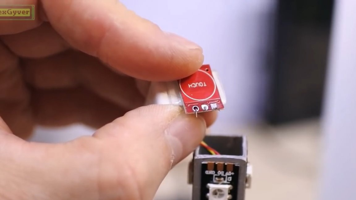
The sensor itself will be mounted on a piece of plastic from the box for laying wires. The sensor must be raised above the profile, otherwise it will not even work on your finger. Glue on double-sided tape.
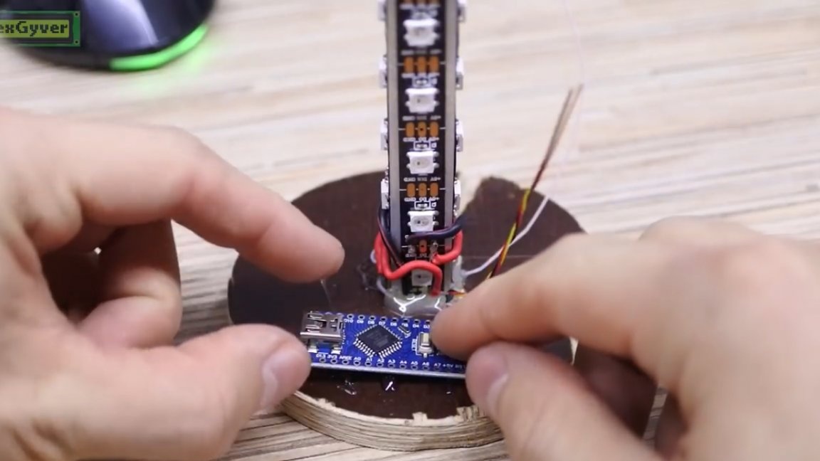
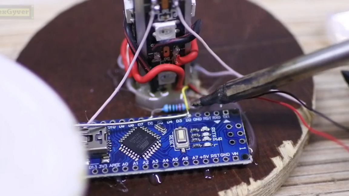
In the base we fasten the arduino. Solder the wires from the power supply directly to the tape, and fix the wire itself to hot glue.
Well, it remains to combine everything else.
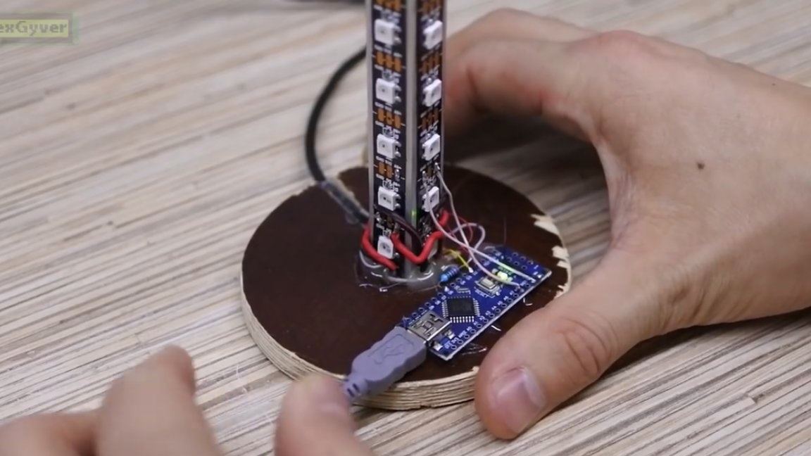
We connect arduino to the computer, with project pages download the archive.
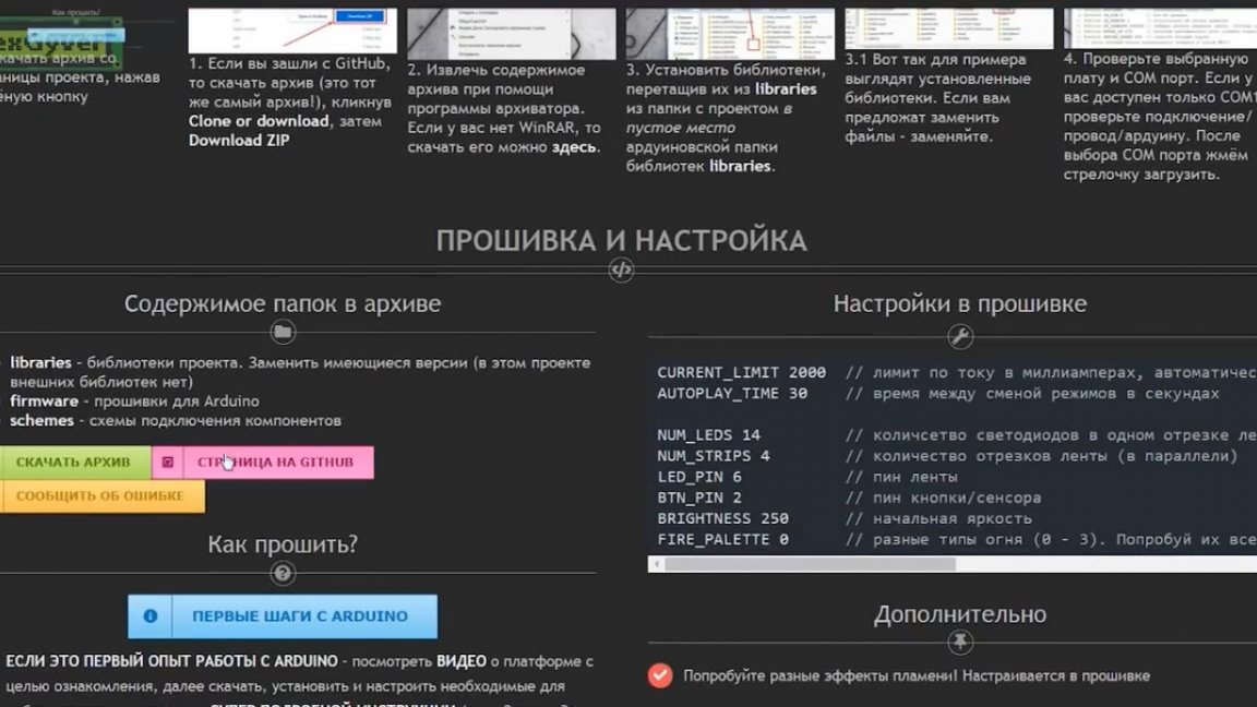
In the downloaded archive we find and open the firmware and configure it for ourselves in the settings, everything is signed there and click download.


Well, actually everything, it remains to cover the tape with a cap and you can use it.
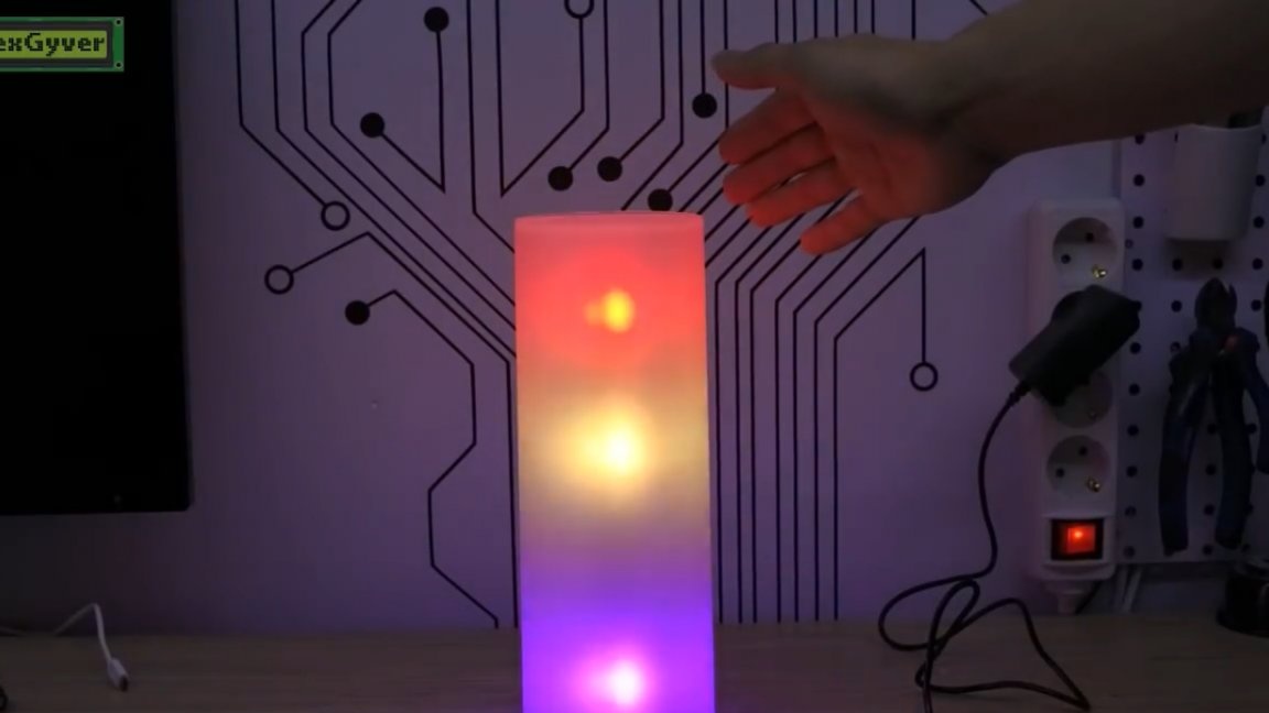
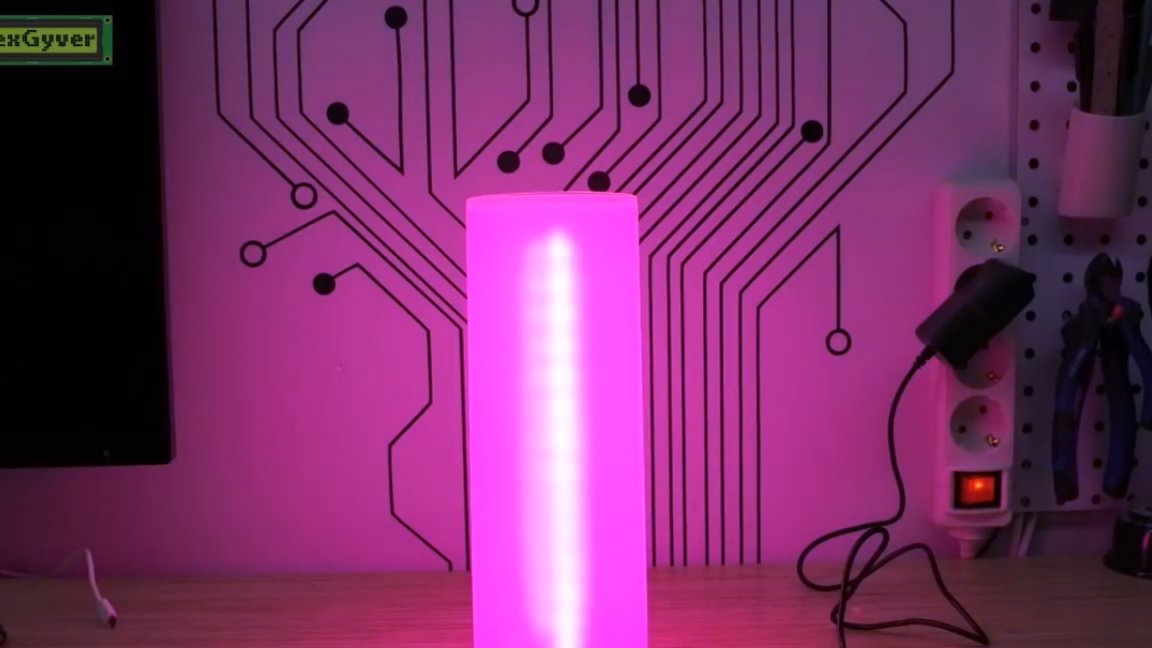
Let’s now figure out how to manage it and what it can do. The first effect is a wandering light.
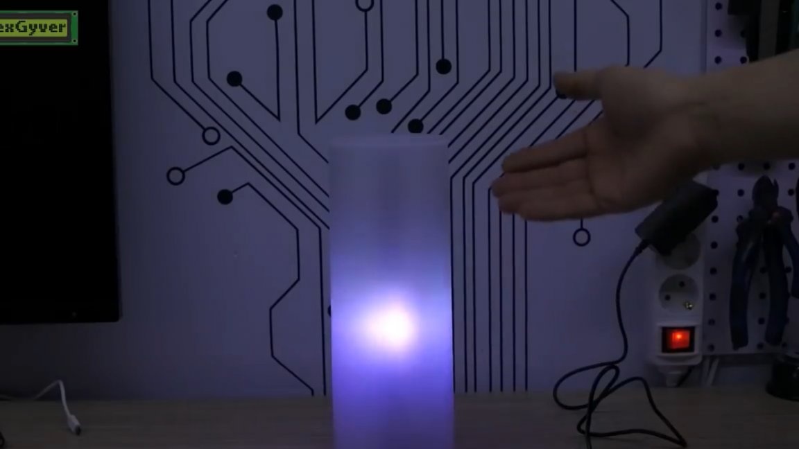
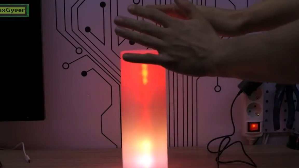
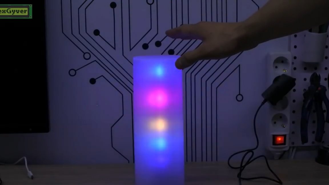
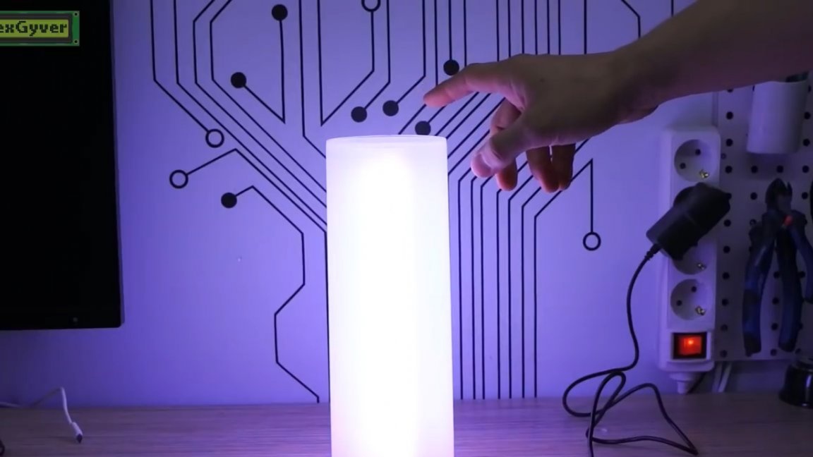
One slap on the sensor in any mode turns the system on and off. Pressing and holding controls brightness. The system remembers the previous direction and changes, and the next time you hold it, it will change the brightness in the other direction, just like in Chinese dimmers for LED strips. Double slap switches the effect to the next. We have fireflies that randomly fly inside the lamp.
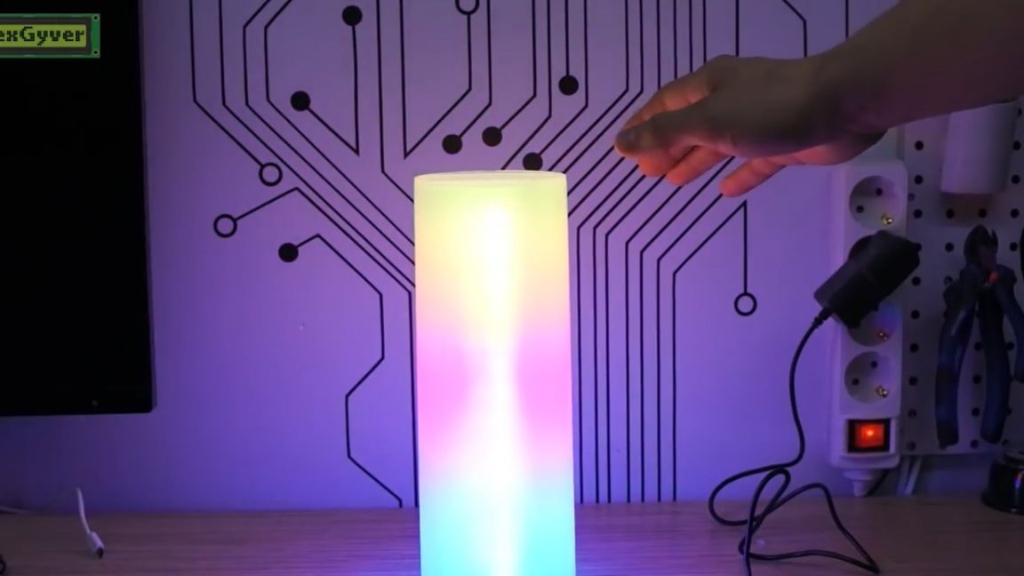
And this is a smooth color change in a circle.
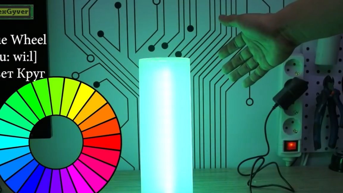
The speed of effects, by the way, can be adjusted in the firmware.
And this is a running rainbow.
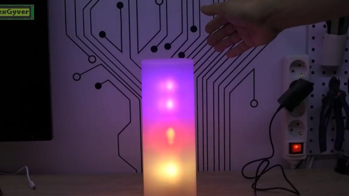
In life, it looks much more saturated, for some reason the camera does not convey the entire color. Perhaps because it is very bright. Further confetti effect, random color flashes:
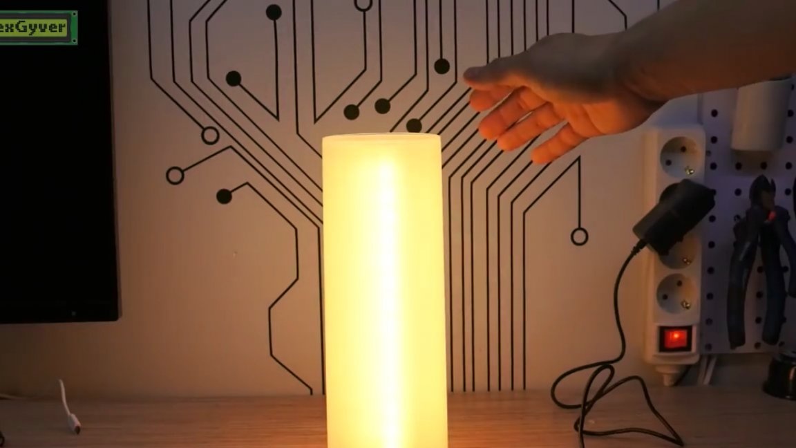
And the last mode is fire:
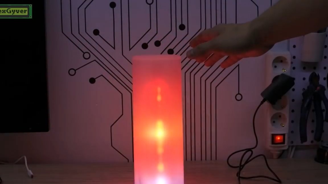
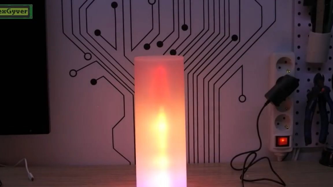
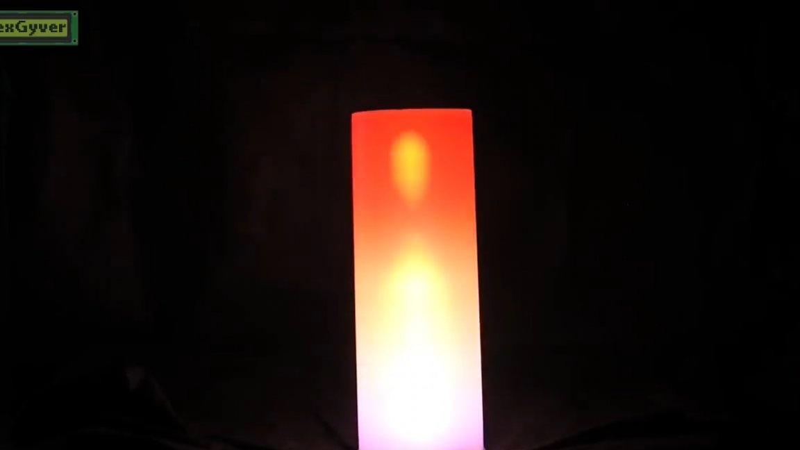
In principle, for the sake of him we made this lamp. In the firmware, you can configure 4 different flame options. Gather yourself such a lamp to see them all. Triple slap turns on the white light mode, the brightness can be adjusted.
That's just this mode is the most eating, if you need maximum brightness, take a powerful power supply. And finally, the quadruple slap on the sensor turns on and off the automatic change of modes, the time between which can also be configured in the firmware. When the lamp is turned on, the automatic change of modes is the default.
Well, actually here we have such a lamp today. And that's all for today. Thank you for attention. See you soon!
Video: