
Greetings the inhabitants of our site!
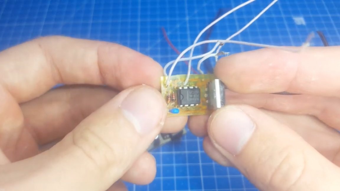
More recently, Roman, the author of YouTube channel "Open Frime TV", needed a powerful PWM controller. The search and verification of various schemes began. As a result, he settled on this option:
The author has already shot videos about PWM controllers more than once, but at the time of their creation he didn’t really understand circuitry, and there was no equipment to fully test the resulting devices.
Now, the author has an oscilloscope, with which you can see all the jambs.

Let's look at the errors so that in the future they are not allowed. The most important mistake is a misunderstanding of the principle of the field effect transistor. Those who have been engaged in electronics for more than a year know that not only voltage, but some current is needed to open a fieldwork.
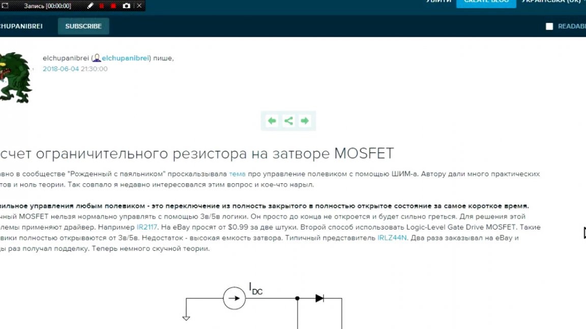
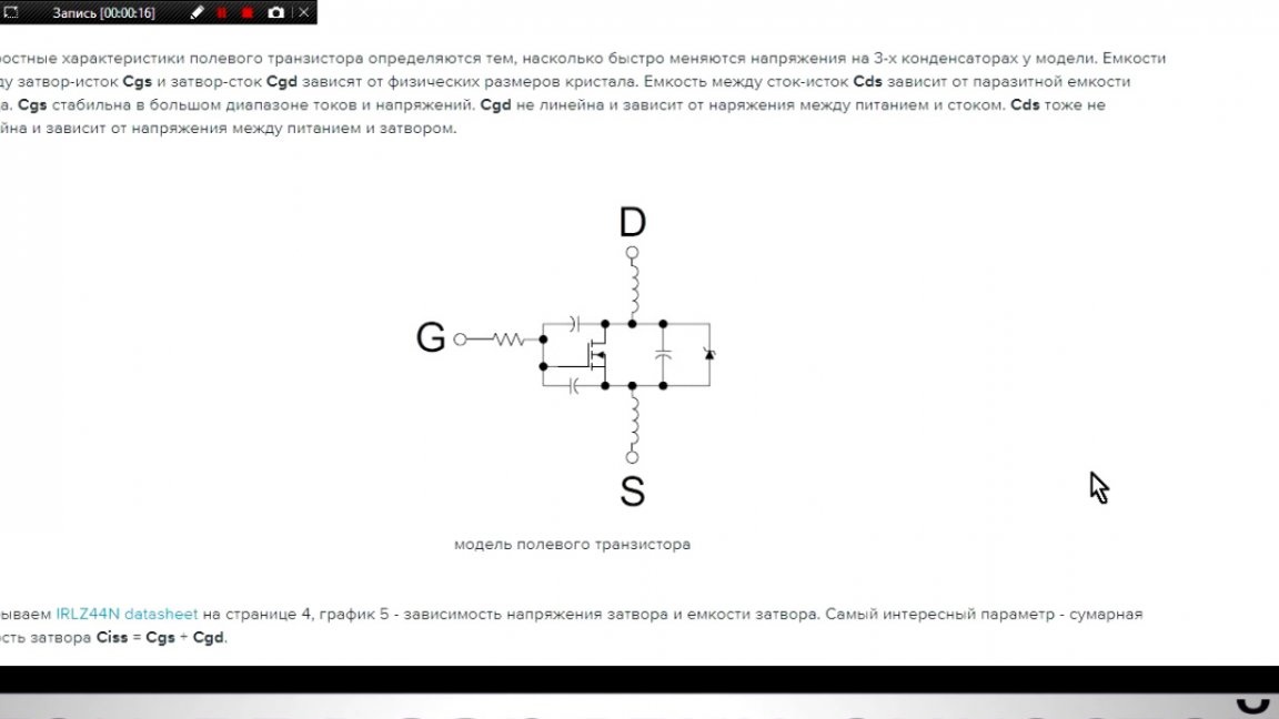
The same applies to closure. If this current is not enough, then the transistor will open more slowly and, therefore, heat up harder.
The heating of mosfets in the key mode appears precisely at the moments of switching, and the faster we switch the transistor, the less it will heat up. Most beginners do not know this and therefore, in some circuits, the power transistor heats up quite a lot. The author had exactly the same, and at that time he did not understand why this was happening.
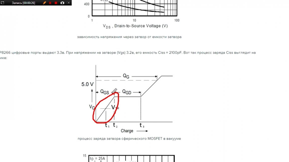
I think everyone who was looking for a PWM controller circuit came across an option with a ne555 chip and a bunch of transistors, but it's worth a look in its datasheet and we will see a maximum output current of 200 mA.
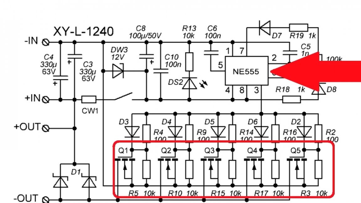
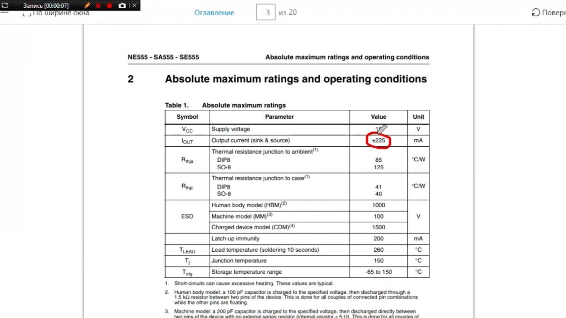
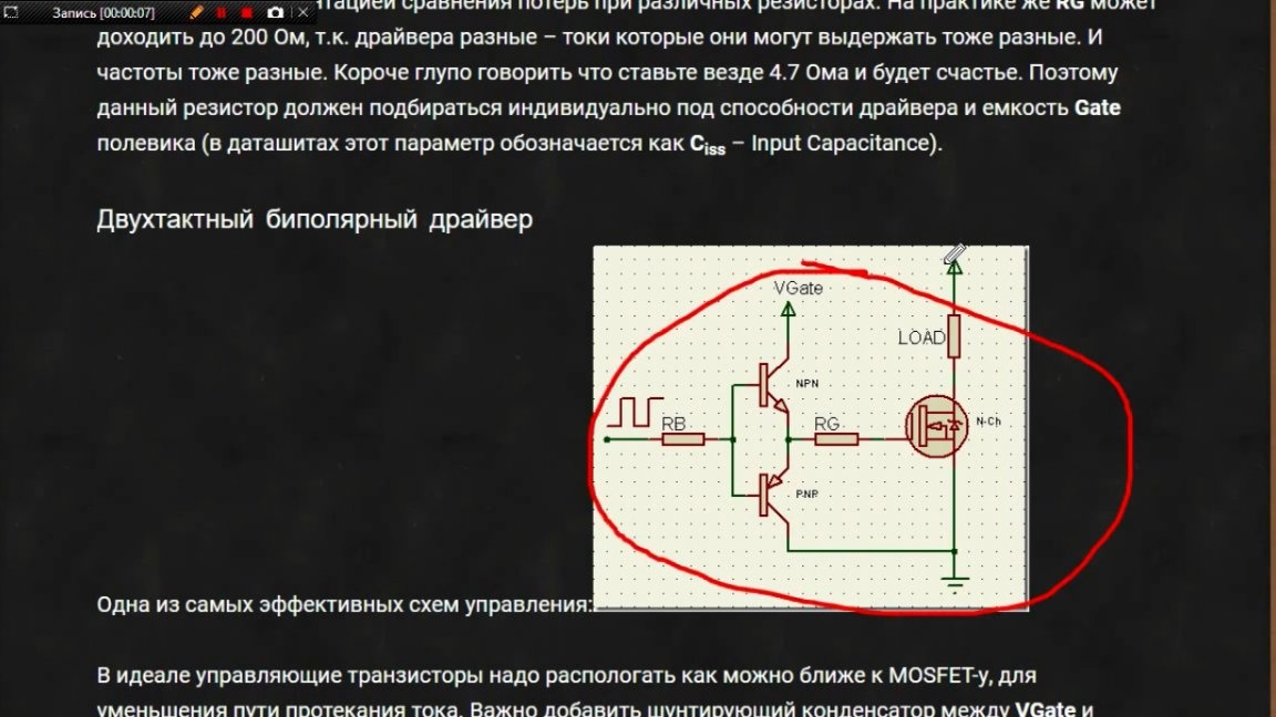
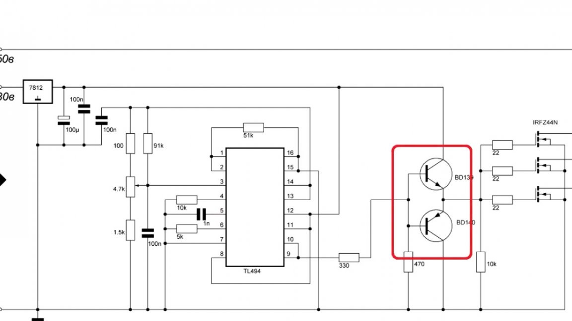
This current is clearly not enough for the correct operation of the device. How then to assemble an excellent PWM controller and reduce its heating? Everything is very simple, it is necessary to put a driver at the output of the control microcircuit, which can provide sufficient current for opening and closing mosfets.
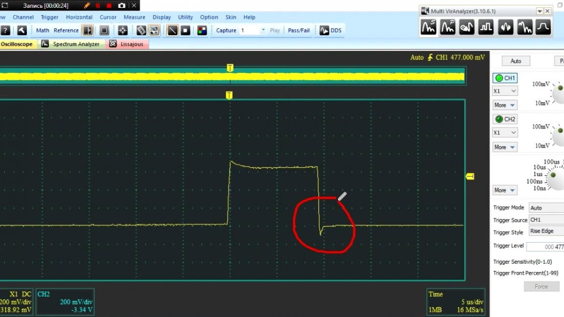
The oscillograms clearly show how the transistor switches without a driver and when it is. Here you can even see with the naked eye the advantages of the driver.

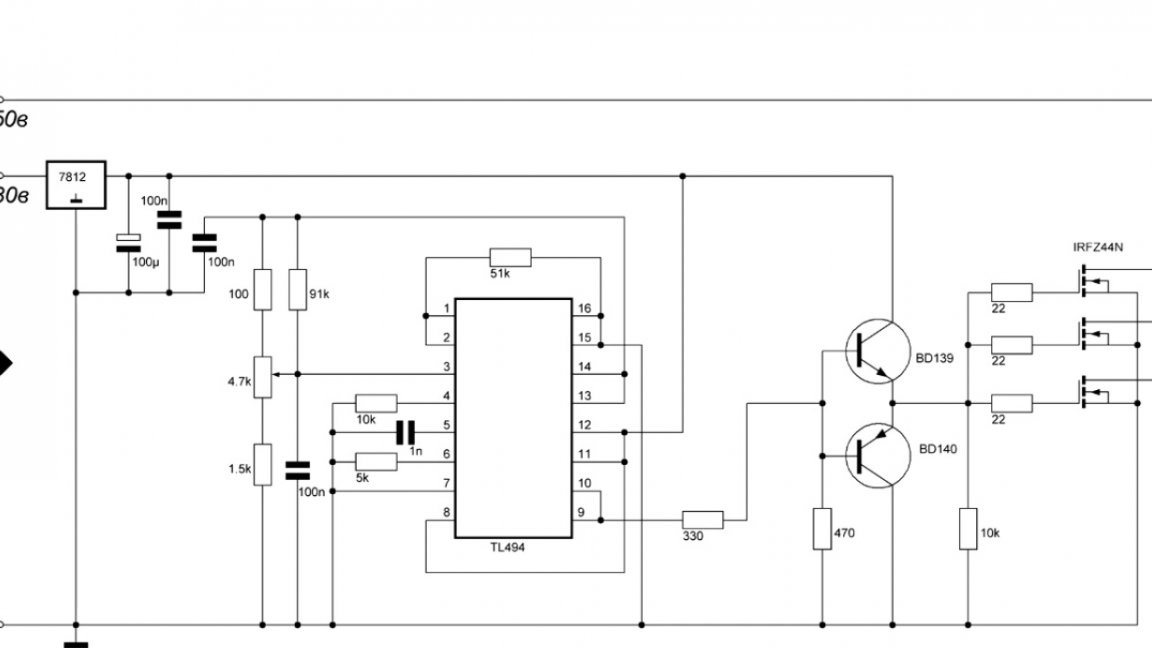
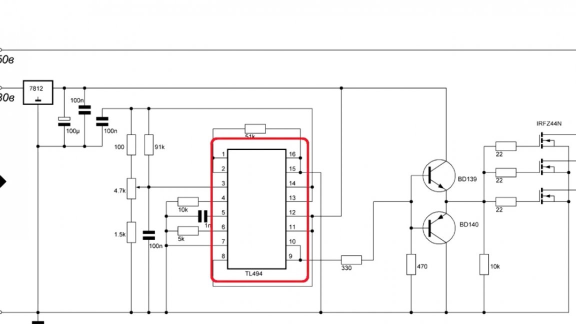
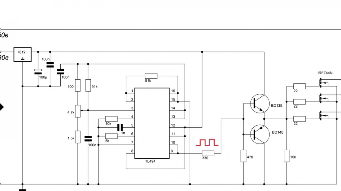
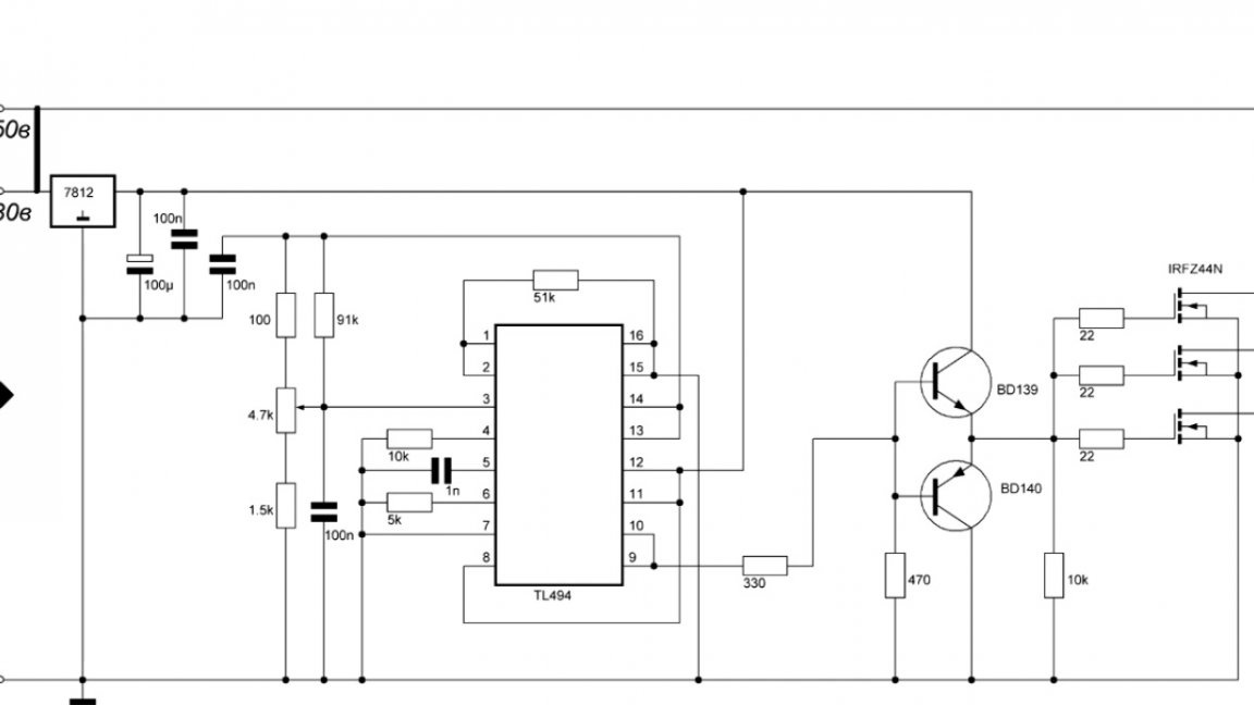
Now let's take a look at device diagram:
As you can see, the author applied TL494 as the master microcircuit.Why exactly her? Yes, because it is very popular and easy to set up.
The author also tried to build PWM on Uc3843, but it has its own characteristics that make assembly difficult. He did it at the 555th, but it was the 494th that attracted the most. You can add a current limiter to it without any problems, but this will already be done for your needs.
Now a few words about the operation of the circuit. TL494 generates rectangular pulses, the frequency of which is set using this capacitor and resistor:
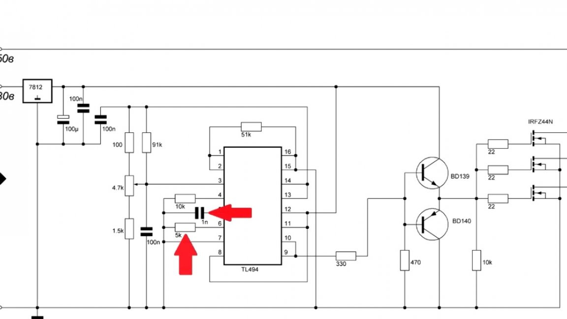
Then these pulses are amplified by the driver and fed to the gates of the transistors.
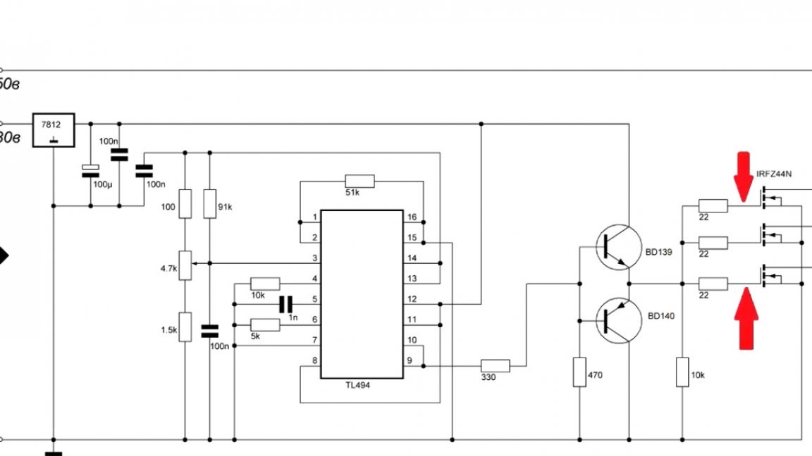
Each gate transistor has its own resistor. This is done to remove ringing when closing.
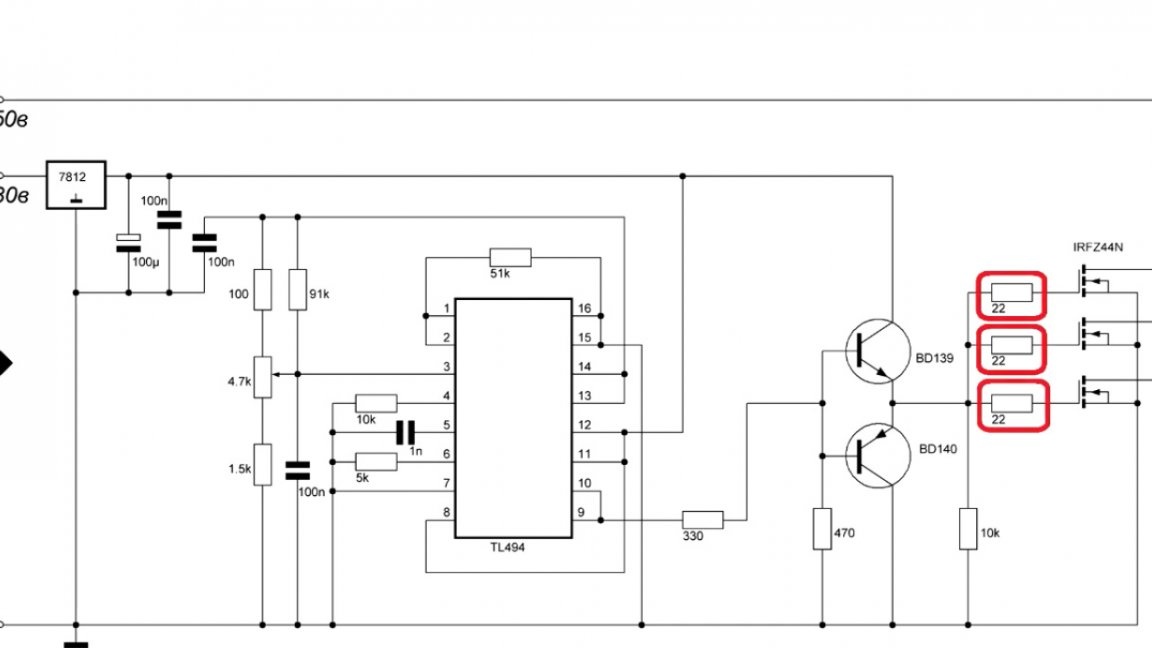
Since these are field-effect transistors, when connected in parallel, they do not need current-limiting resistors, which increases the efficiency of the circuit. Also in the diagram we can see 2 input voltages.
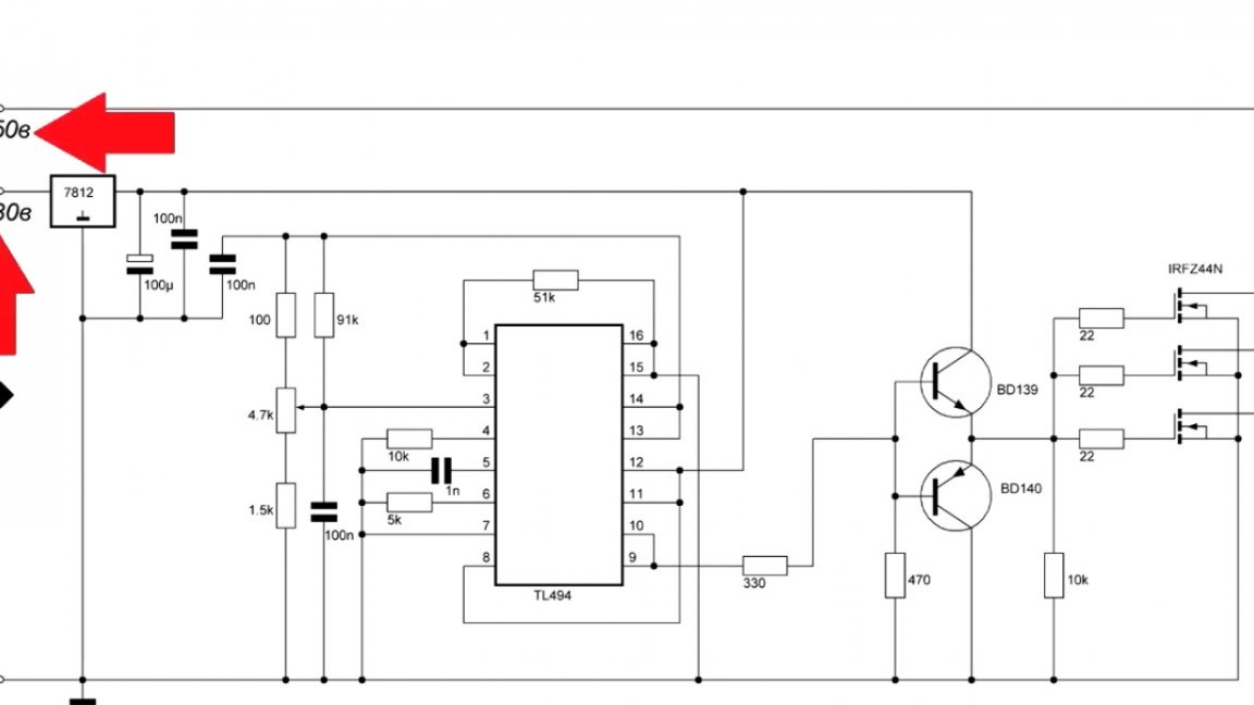
This is done in order to expand the limits of the PWM controller itself. If the input voltage is in the region of 13-30V, then you can install a jumper and power the circuit with one voltage.
You also need to say a few words about transistors.
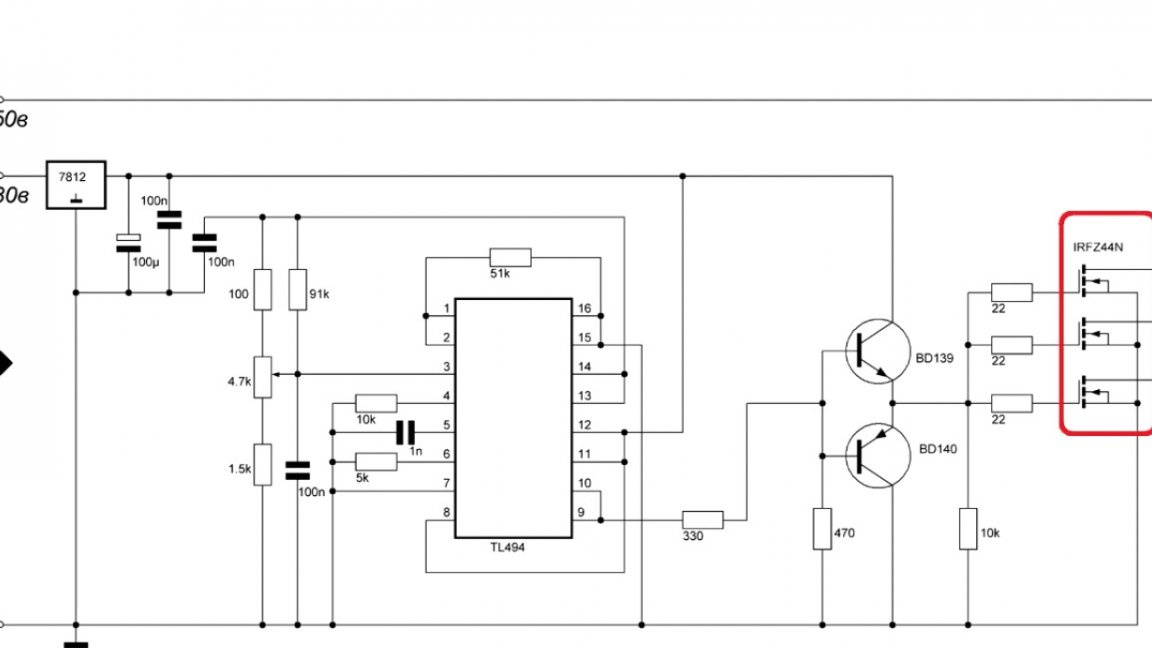
IRFZ44N is rated for 50V.
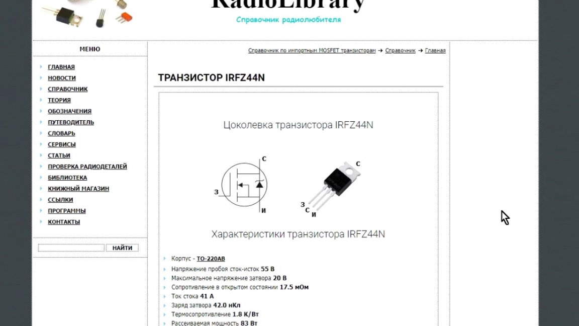
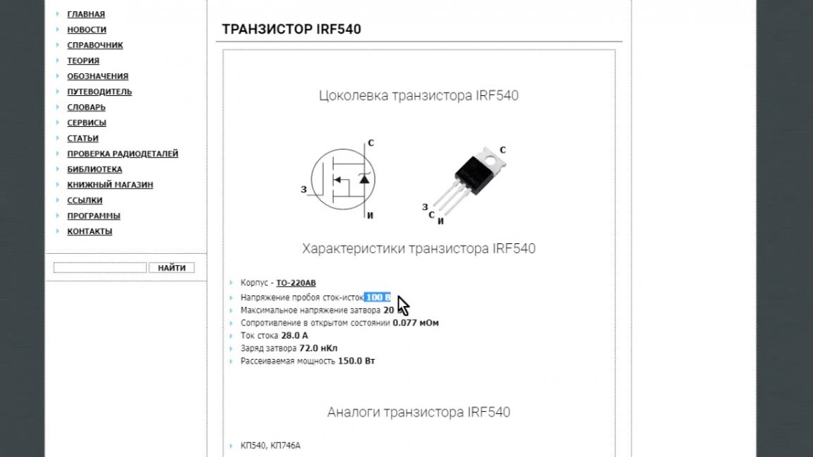
If you need to control a higher voltage, then you need to replace the transistors to your parameters. For example, the IRF540 is already rated for 100V.
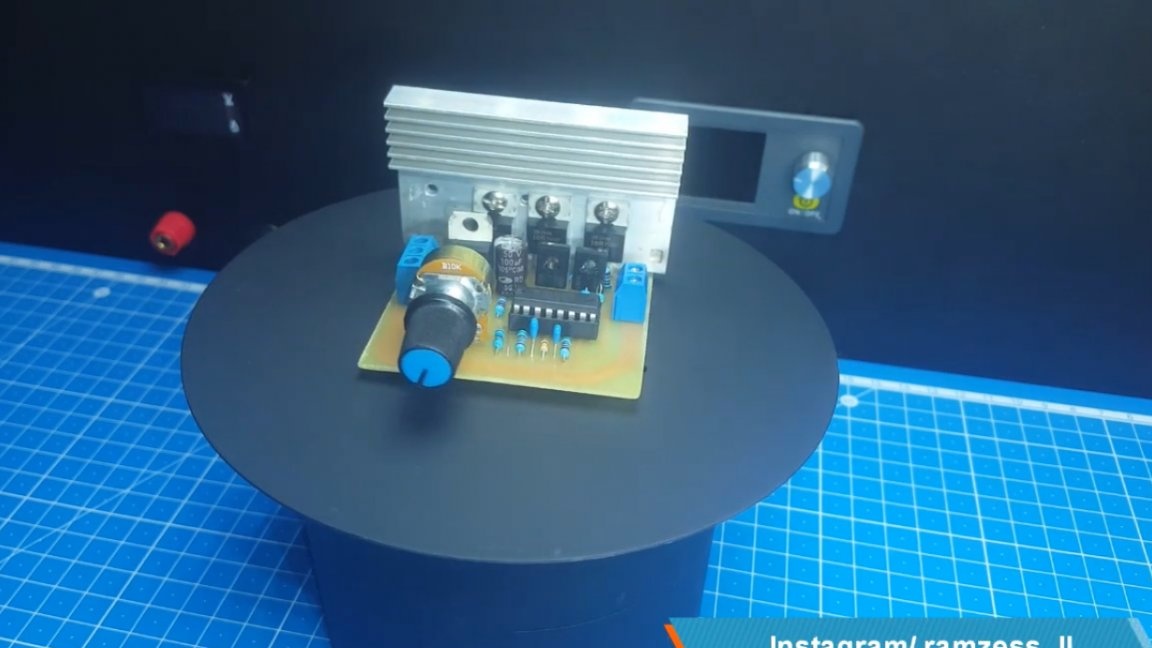
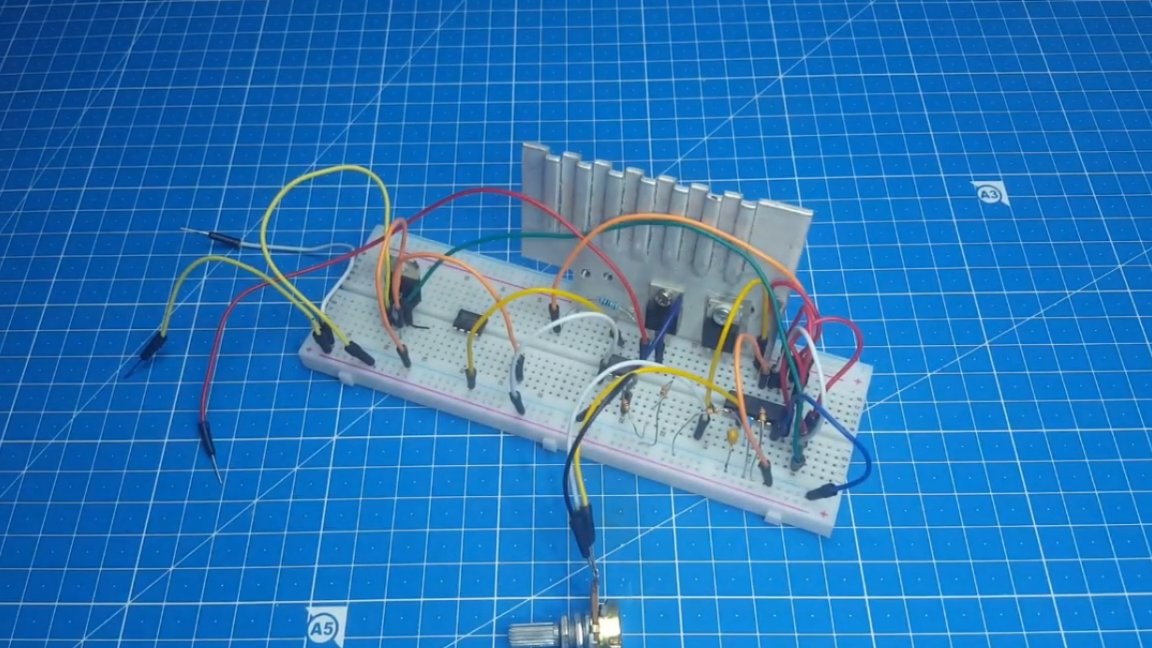
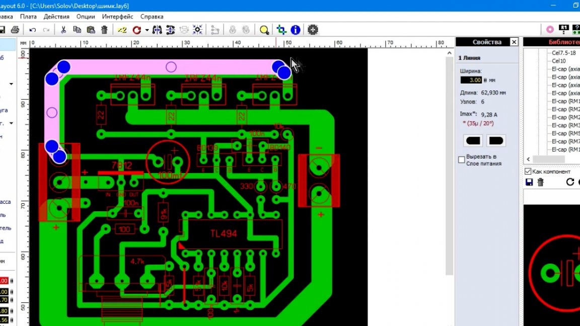
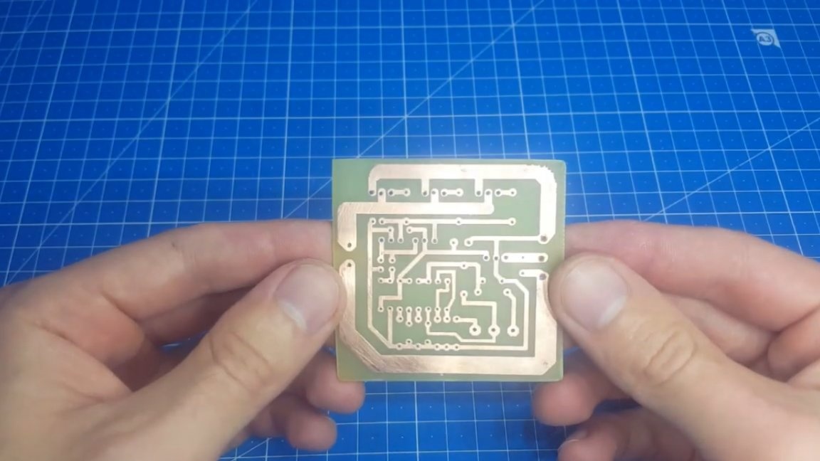
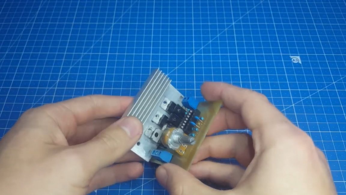
With the circuit finished, consider a circuit board.
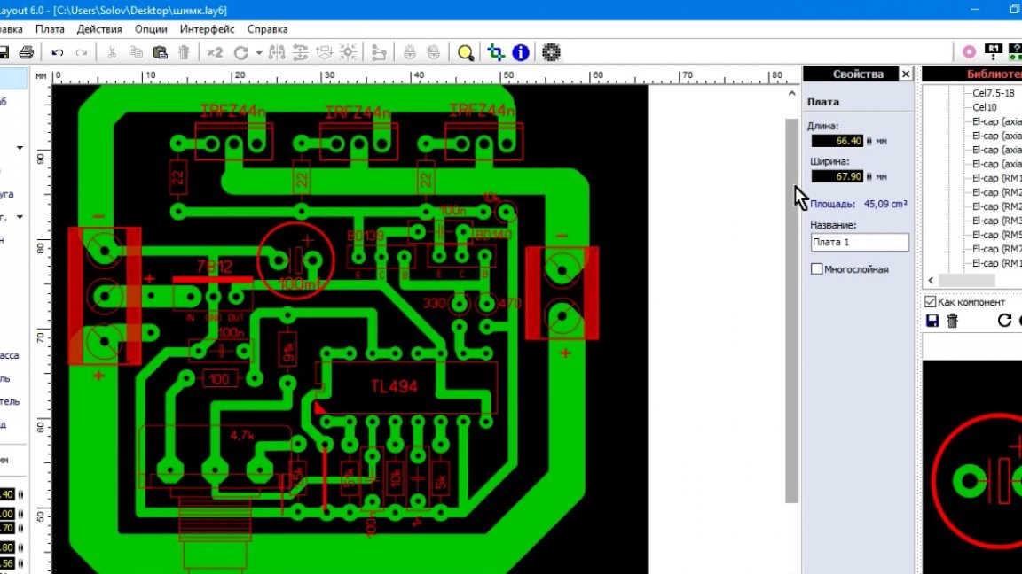
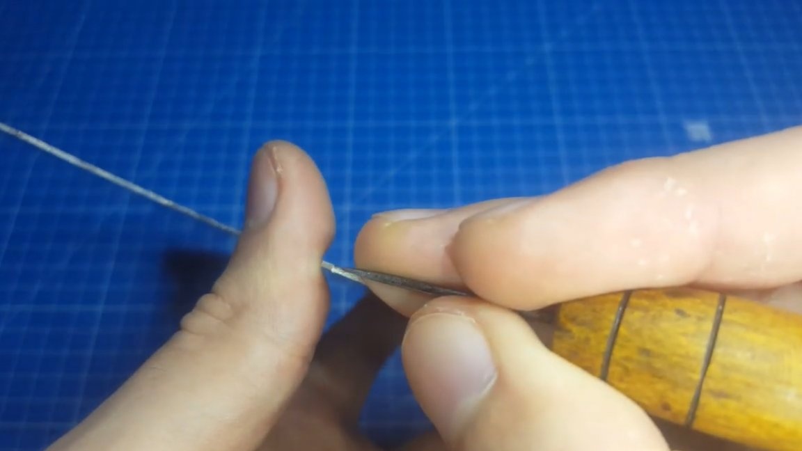
Power lines are striking here. They are not very large, but everything is compensated after the assembly of the device. They will have to be soldered with a copper wire to increase the conductivity. This will be the best solution, since there is no more sense in making the track itself, it has a small cross section and will not be able to conduct a large current.
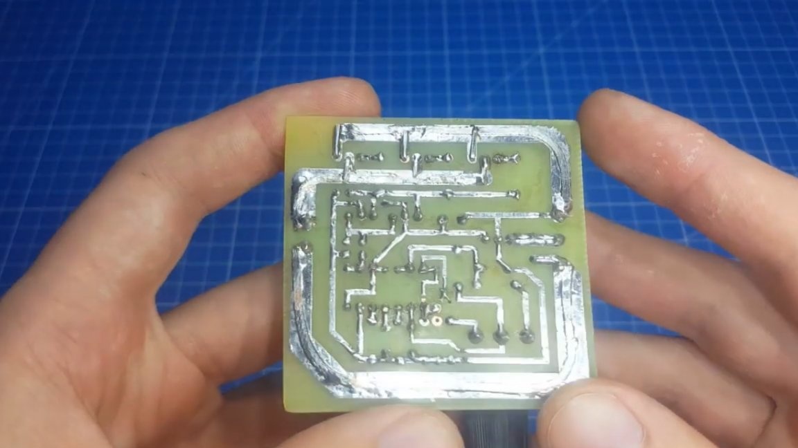
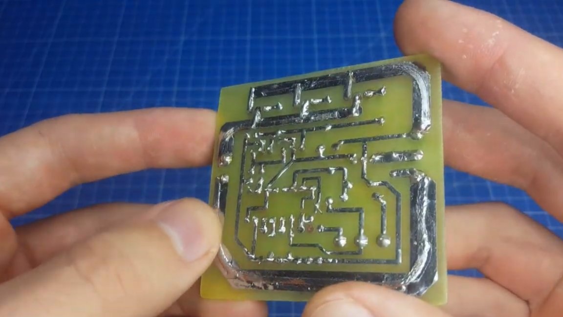
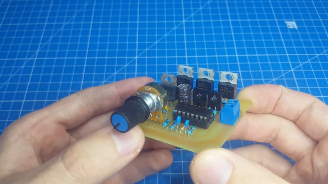
We also figured out the board. Let's collect it. This will not be difficult, there are few details and the complexity is minimal.
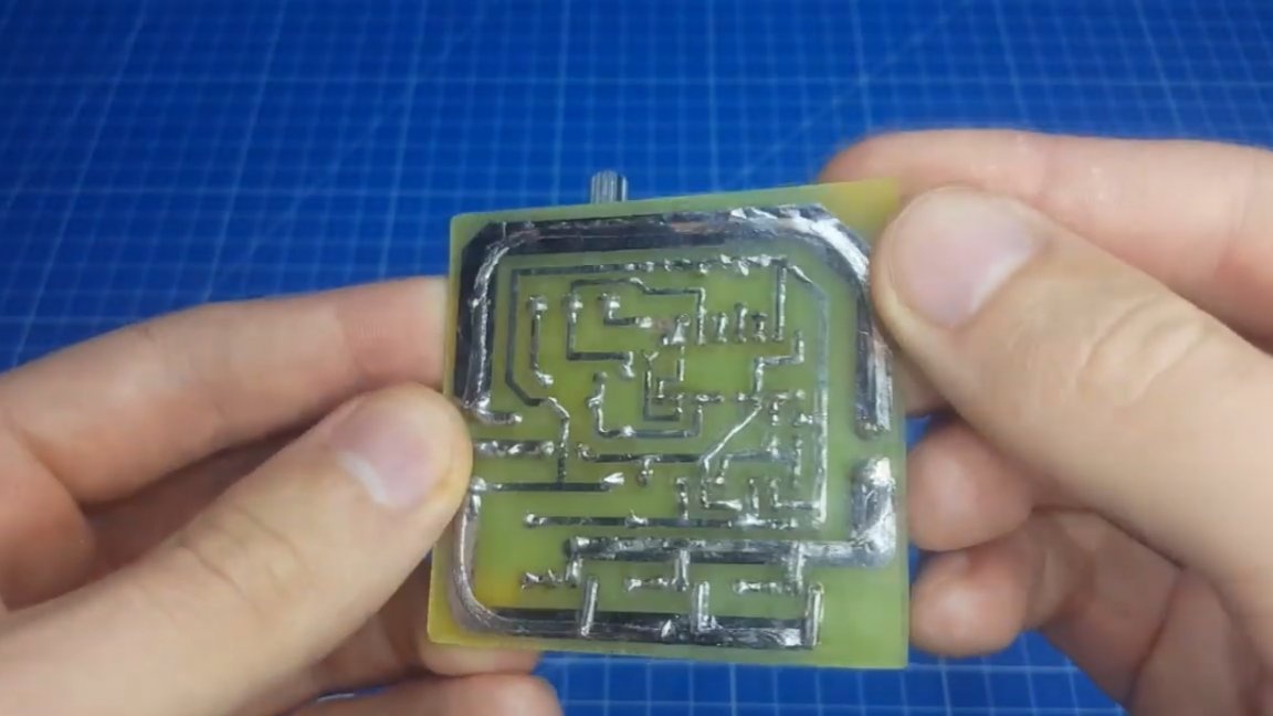
Power tracks disappeared from the reverse side. Now you need to install transistors on the radiator, you do not think that we completely got rid of heating.
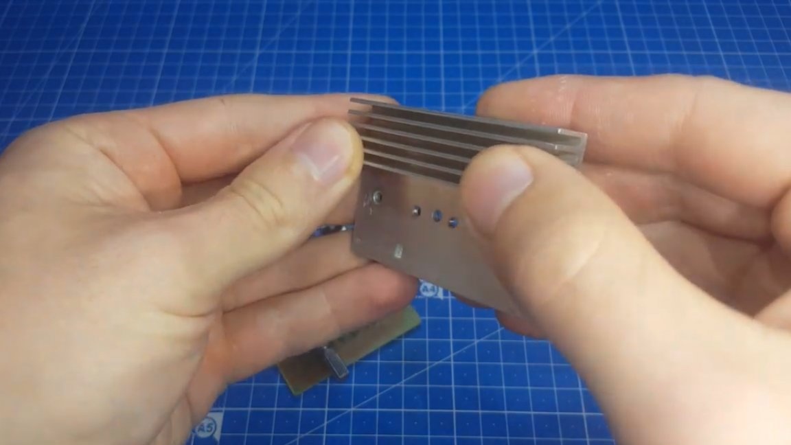
When installing, you can not use insulating substrates, since transistors are connected in parallel.
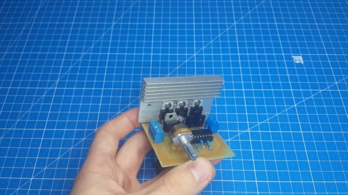
With such a radiator, currents up to 20A can be switched. At higher currents, a larger radiator is required.

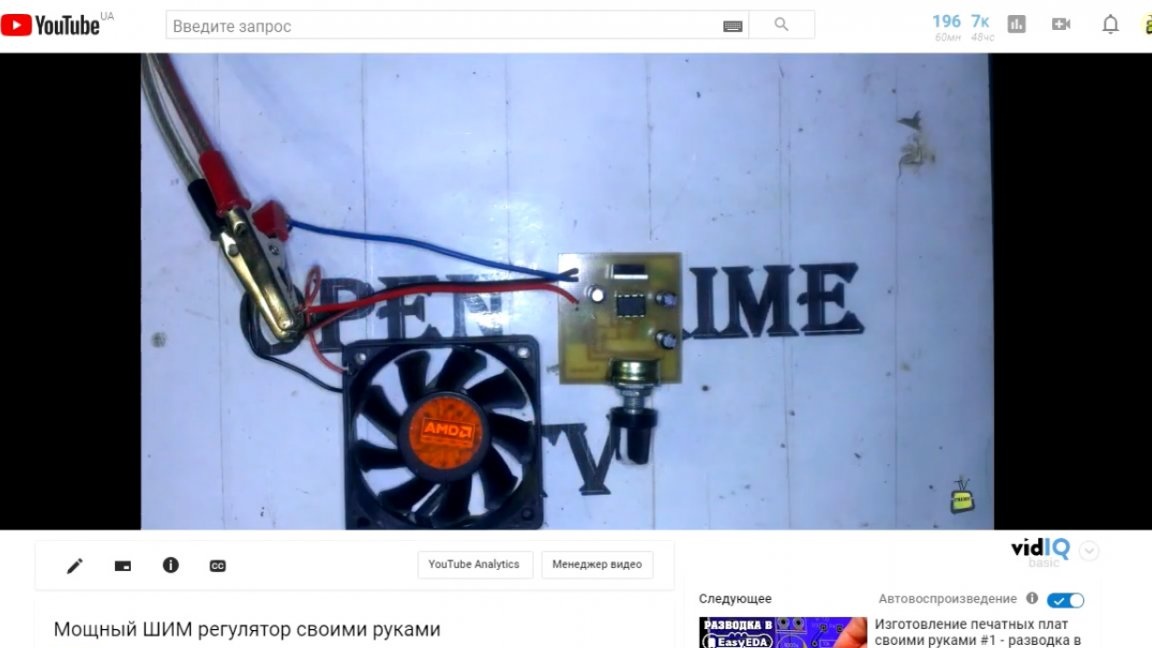
Well, in the end you can make tests. We apply voltage to the circuit (in this case it is 28V) and turn it on.
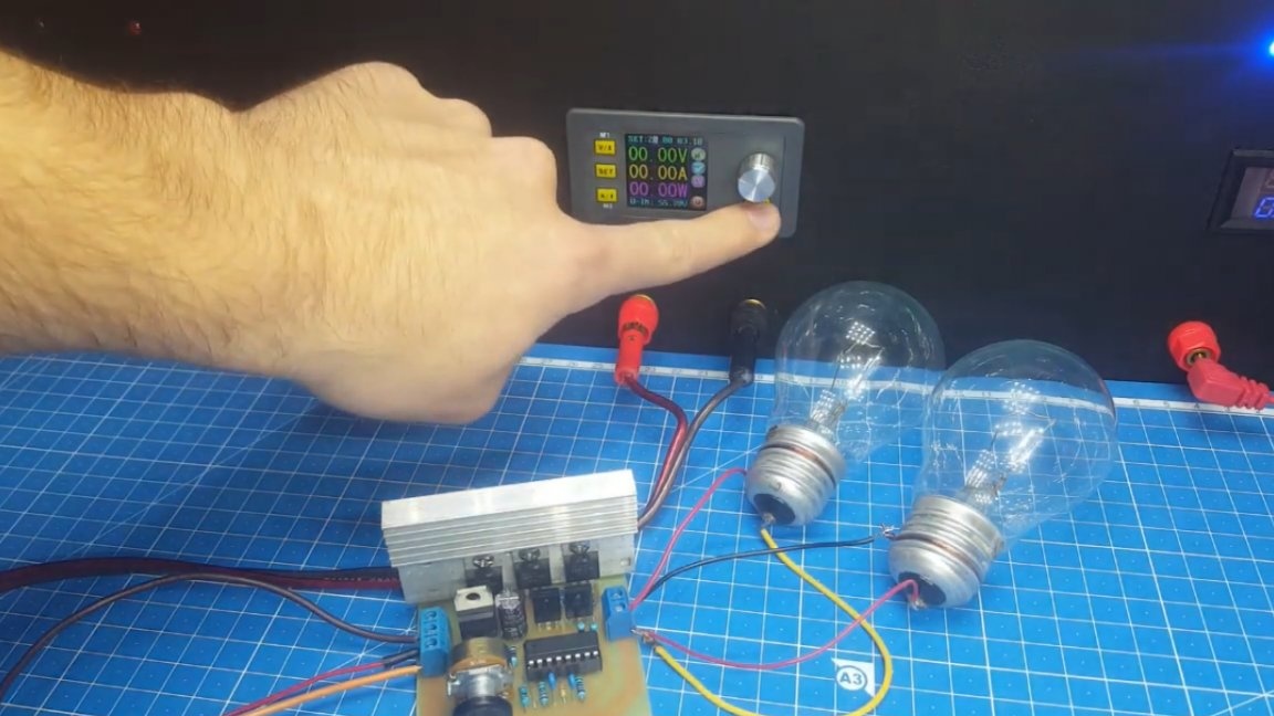
To begin with, we connect 2 incandescent lamps with a power of 100W, designed for a voltage of 36V.
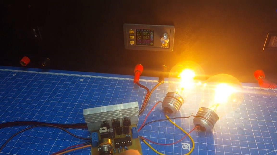
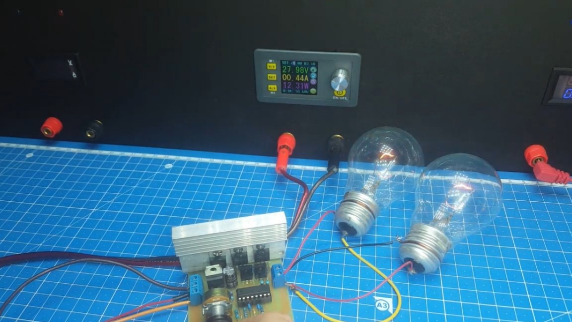
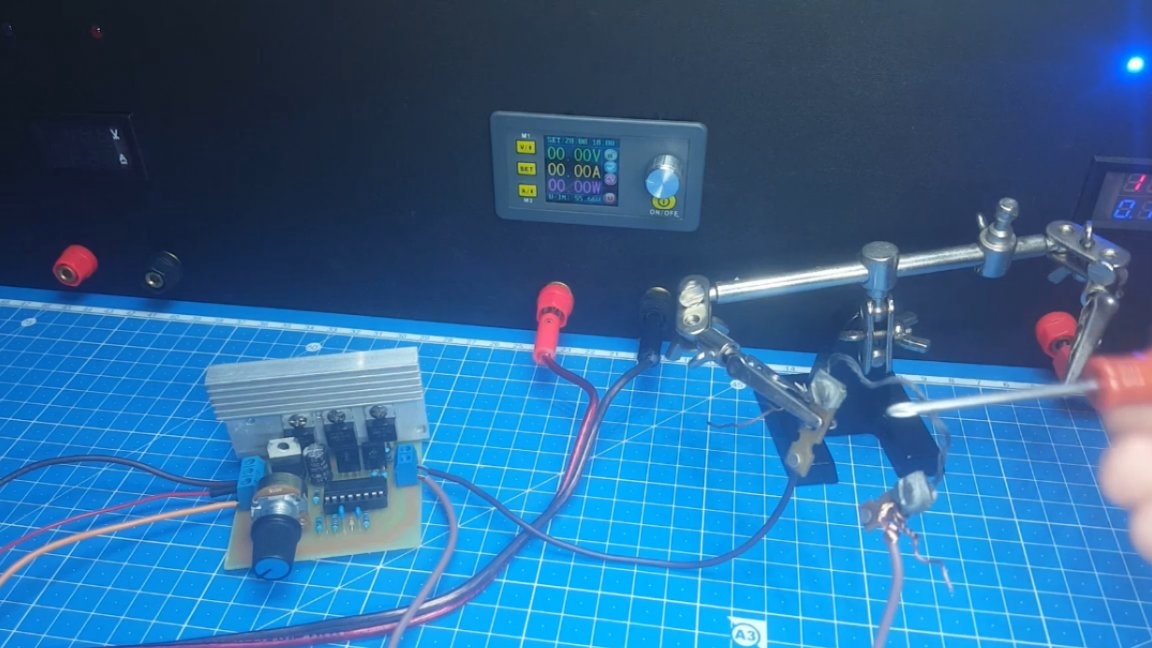
But it is, a kindergarten, the scheme copes with one or two. Now you can take a more powerful load, for example, such a nichrome spiral.
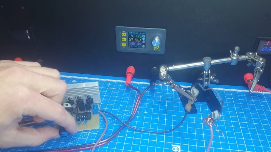
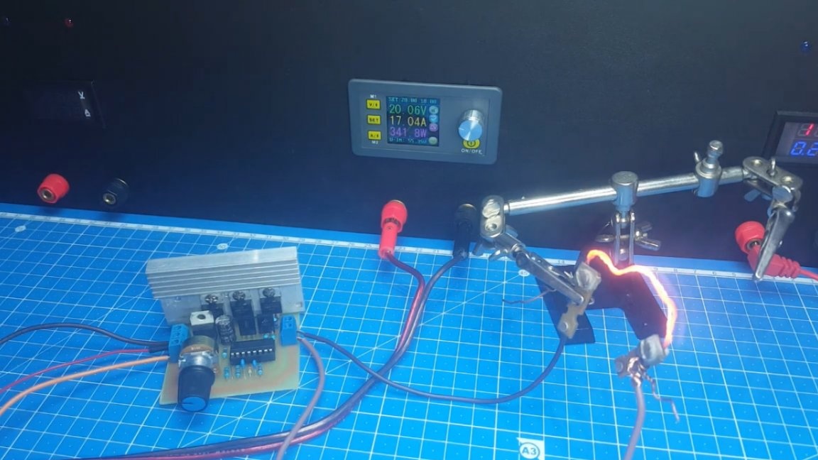
As you can see, the current is going pretty big, but the circuit is doing well. The author collected the board itself to one person for a powerful DC motor. So far there have been no complaints, so you can advise her to repeat. Well, that’s all. Thank you for attention. See you soon!
Video: