
The most difficult to manufacture and most important for turbine operation is the compressor stage. Usually, it requires an accurate CNC machining tool or manual drive to assemble it. Fortunately, the compressor runs at low temperatures and can be printed on a 3D printer.
Another thing that is usually very difficult to reproduce in home conditions, this is the so-called "nozzle blade" or simply NGV. Through trial and error, the author found a way to do this without using a welding machine or other exotic tools.
What is needed:
1) 3D printer capable of working with PLA thread. If you have an expensive one, such as Ultimaker, this is great, but cheaper, such as Prusa Anet, will do the trick too;
2) You must have enough PLA to print all the parts. ABS is not suitable for this project, as it is too soft. You can probably use PETG, but this has not been tested, so do it at your own risk;
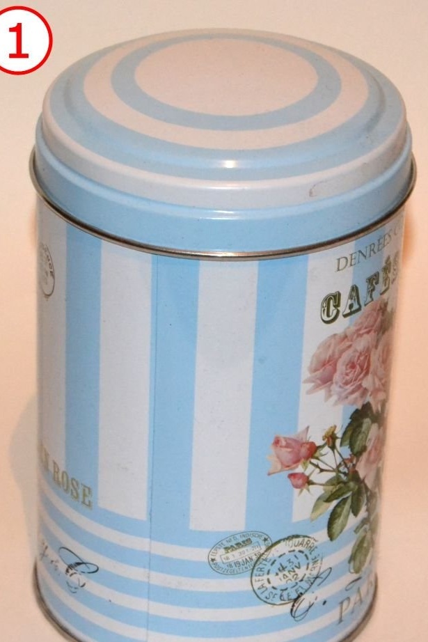
3) A can of the appropriate size (diameter 100 mm, length 145 mm). Preferably, the jar should have a removable lid. You can take a regular can (say, from pieces of pineapple), but then you will need to make a metal lid for it;
4) Galvanized iron sheet. A thickness of 0.5 mm is optimal. You can choose a different thickness, but you may have difficulty bending or grinding, so be prepared. In any case, you will need at least a short strip of galvanized iron with a thickness of 0.5 mm to make a spacer for the turbine casing. Fits 2 pcs. Size 200 x 30 mm;
5) A stainless steel sheet for manufacturing a turbine wheel, NGV wheel and turbine housing. Again, a thickness of 0.5 mm is optimal.
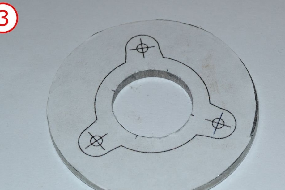
6) A solid steel rod for manufacturing a turbine shaft. Caution: mild steel just doesn't work here. You will need at least some carbon steel. Hard alloys will be even better. The diameter of the shaft is 6 mm. You can choose a different diameter, but then you will need to find the right materials for the manufacture of the hub;
7) 2 pcs. 6x22 bearings 626zz;
8) 1/2 "nozzles 150 mm long and two end fittings;
9) a drilling machine;
10) Sharpened
11) dremel (or something similar)
12) Hacksaw for metal, pliers, screwdriver, M6 die, scissors, vice, etc.
13) a piece of pipe made of copper or stainless steel for atomizing fuel;
14) A set of bolts, nuts, clamps, vinyl tubes and other things;
15) propane or butane burner
If you want to start the engine, you will also need:
16) Propane tank. There are gasoline or kerosene engines, but making them run on these fuels is a bit difficult. It is better to start with propane, and then decide whether you want to switch to liquid fuel or are you already satisfied with gas fuel;
17) A pressure gauge capable of measuring a pressure of several mm water column.
18) Digital tachometer for measuring turbine speed
19) Starter. To start a jet engine, you can use:
Fan (100 W or more). Better centrifugal)
an electric motor (with a power of 100 W or more, 15,000 rpm; you can use your dremel here).
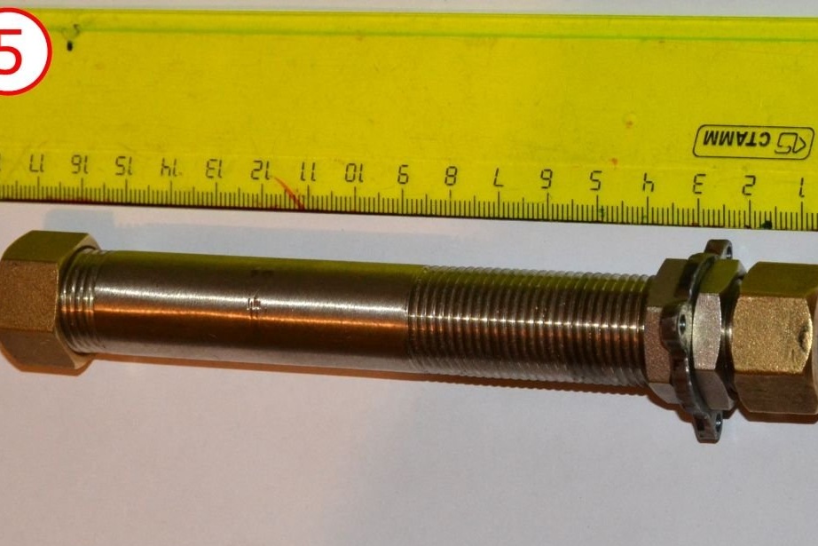
Make the hub
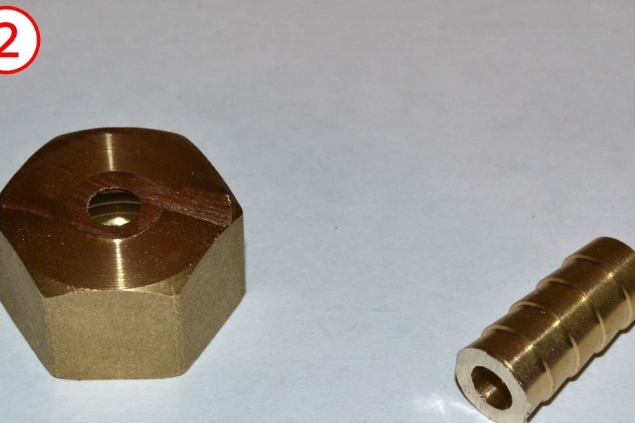
The hub will be made of:
1/2 "branch pipe 150 mm long;
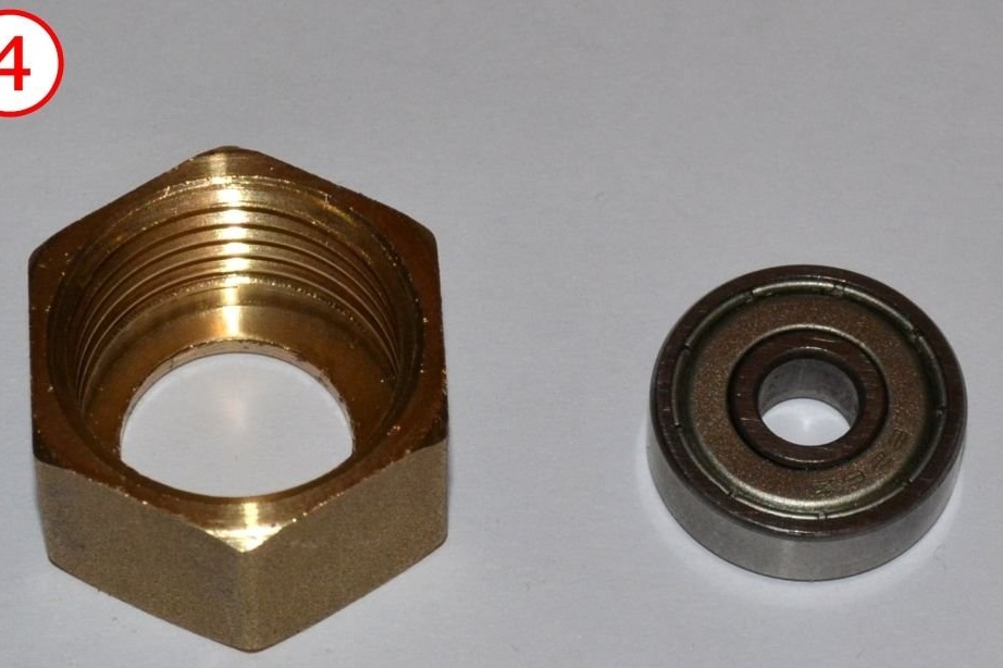
two 1/2 "fittings for hoses;
and two 626zz bearings;
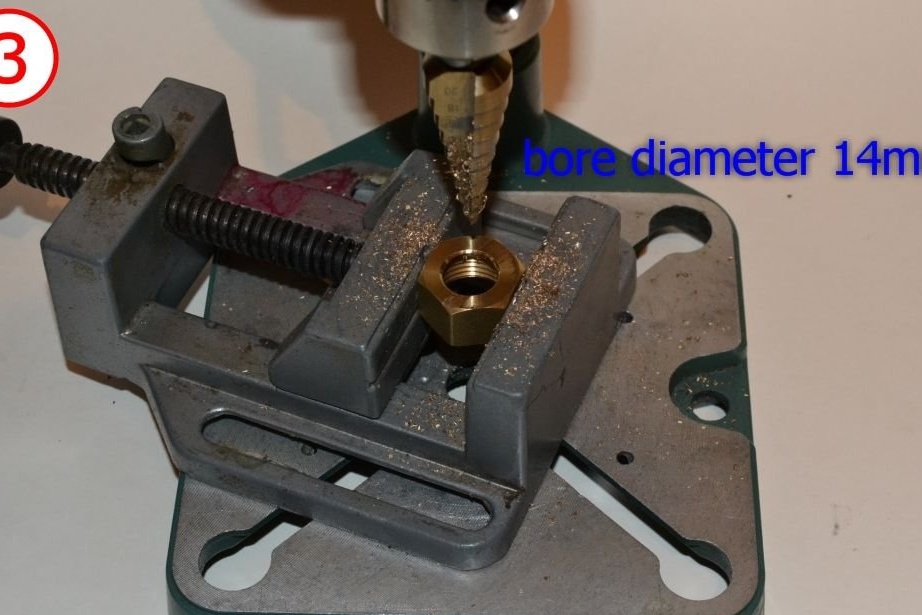
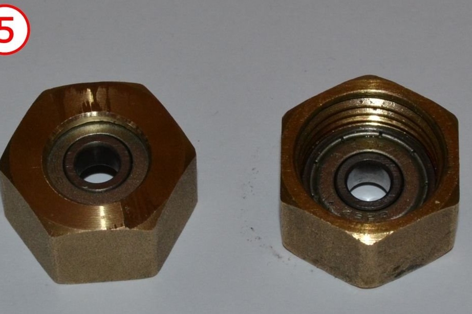
With a hacksaw, cut the Christmas trees from the fittings, and use a drill to enlarge the remaining holes. Insert the bearings into the nuts and screw the nuts onto the nozzle. The hub is ready.
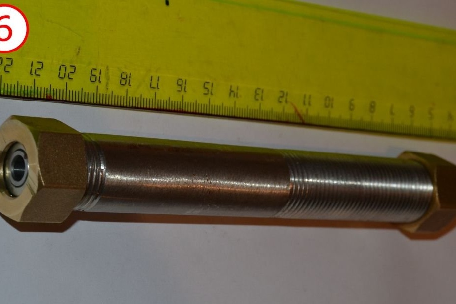
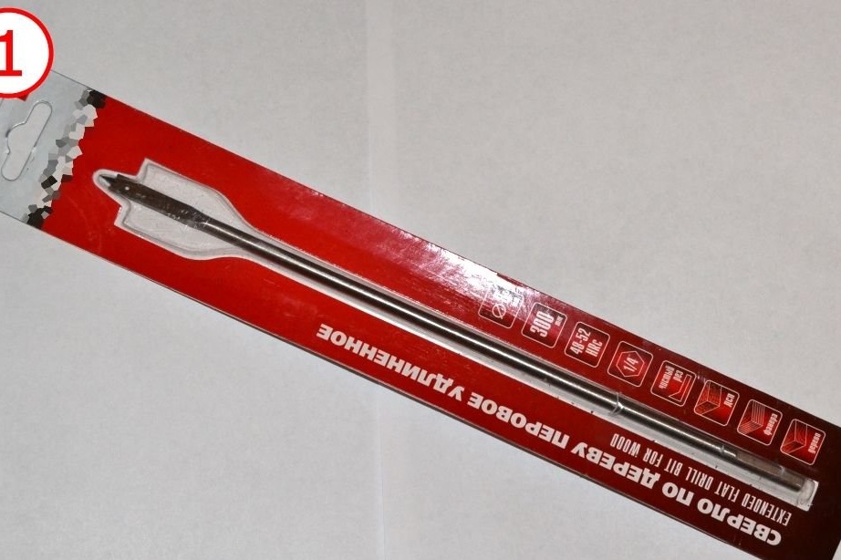
Make a shaft
The theory (and experience to some extent) says that it makes no difference whether you make a shaft from mild steel, hard steel or stainless steel. So choose the one that is more accessible to you.
If you expect to get decent traction from a turbine, it is best to use a steel rod with a diameter of 10 mm (or more). However, at the time of writing, there was a shaft of only 6 mm.
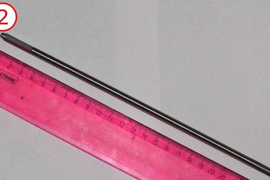
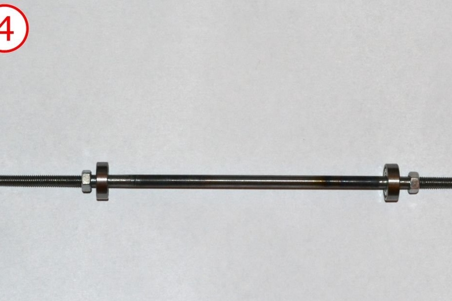
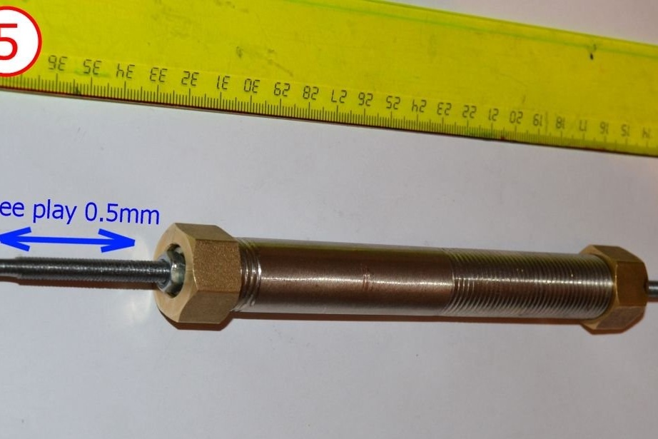
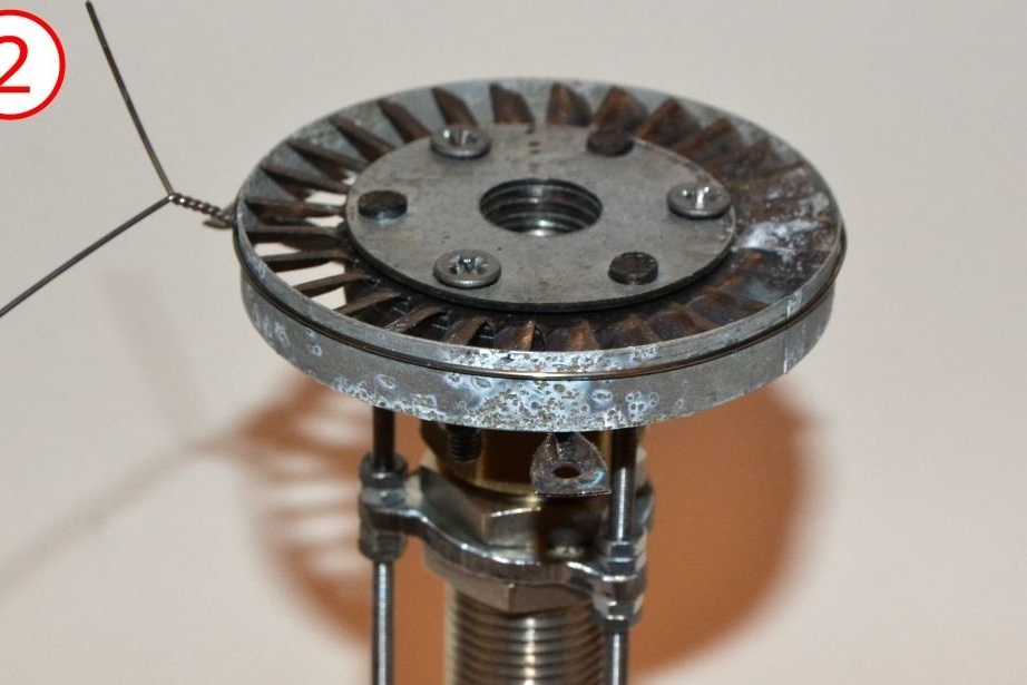
Cut the M6 thread, on one side, with a length of 35 mm. Next, you need to cut the thread from the other end of the rod so that when the rod is inserted into the hub (the bearings abut against the end of the nozzle they are tightened with the nuts you made from the hose fittings) and when the lock nuts are screwed to the end of the thread on both sides, between nuts and bearings leave a small clearance. This is a very complicated procedure. If the thread is too short and the longitudinal play is too large, you can cut the thread a little further. But if the thread seems too long (and there is no longitudinal gap at all), it will be impossible to fix it.
As an option, the shafts from the laser printer, they are exactly 6 mm in diameter. Their disadvantage is that their limit is 20-25000 rpm. If you want higher revs - use thicker rods.
3D printing of turbine wheel and NGV matrixes
For the manufacture of a turbine wheel, or rather its blades, press dies are used.
The shape of the blade becomes smoother if you press the blade not to the final shape in one step (passage), but to some intermediate shape (1st pass) and only then to the final shape (2nd pass). Therefore, there is an STL for both types of molds. For the 1st pass and for the second.
Here are the STL files for the NGV wheels and the STL files for the turbine wheel matrices:
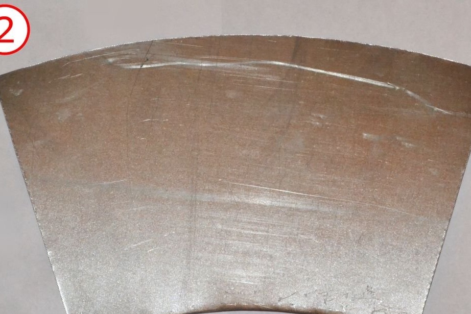
Impeller manufacturing

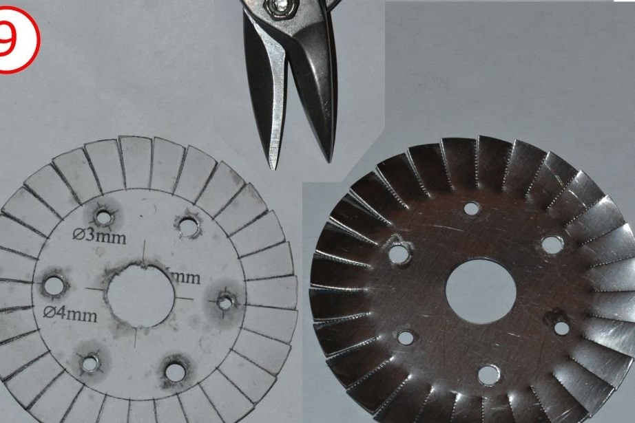
This design uses 2 types of steel wheels. Namely: turbine wheel and NGV wheel. Stainless steel is used for their manufacture. If they were made of lightweight or galvanized material, they would barely be enough to show how the engine works.
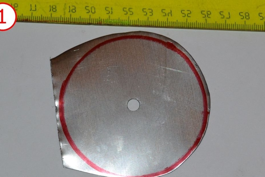
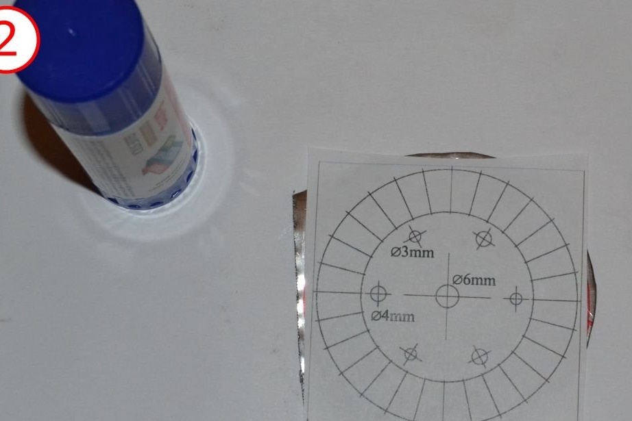
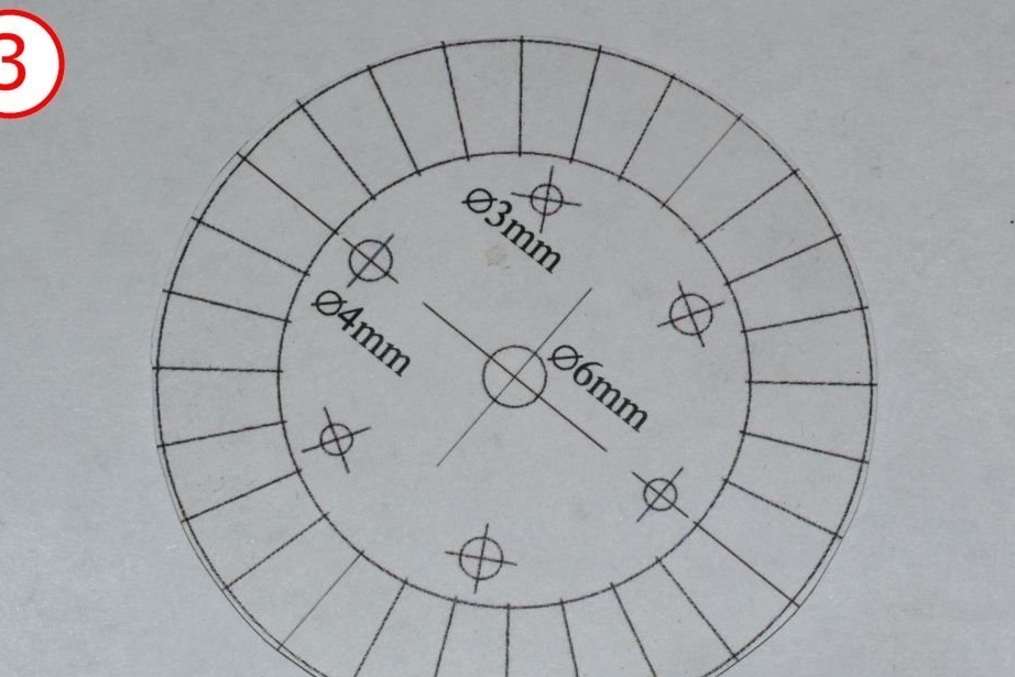
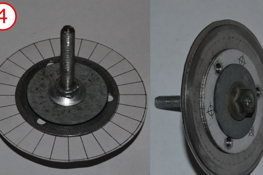
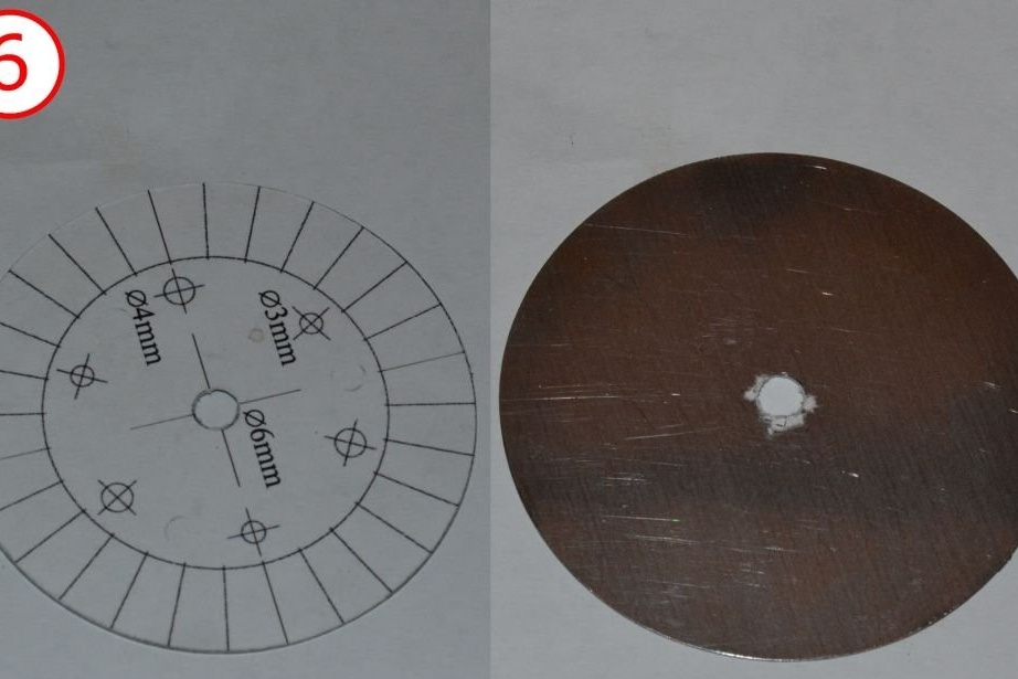
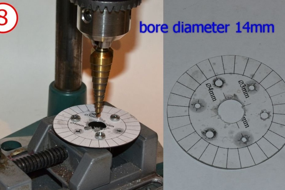
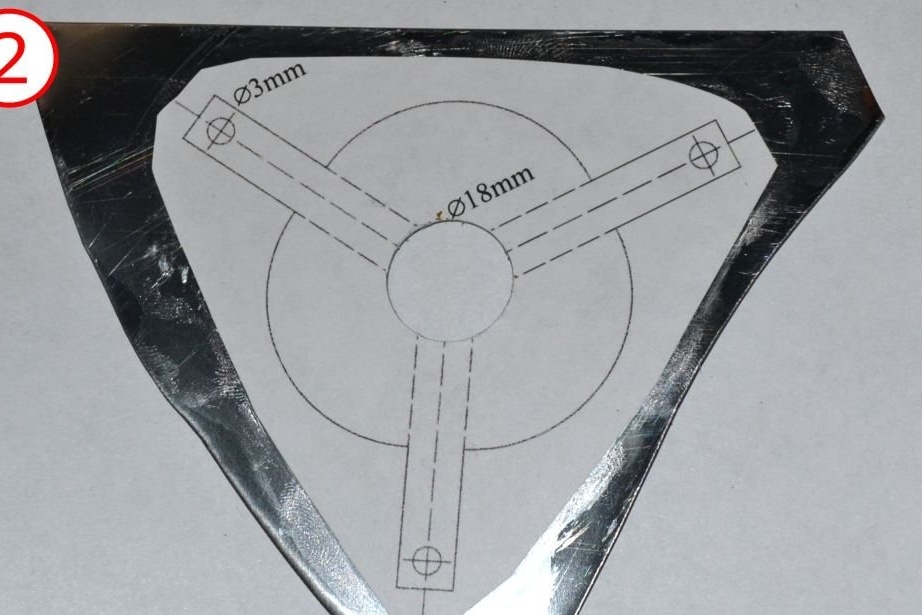
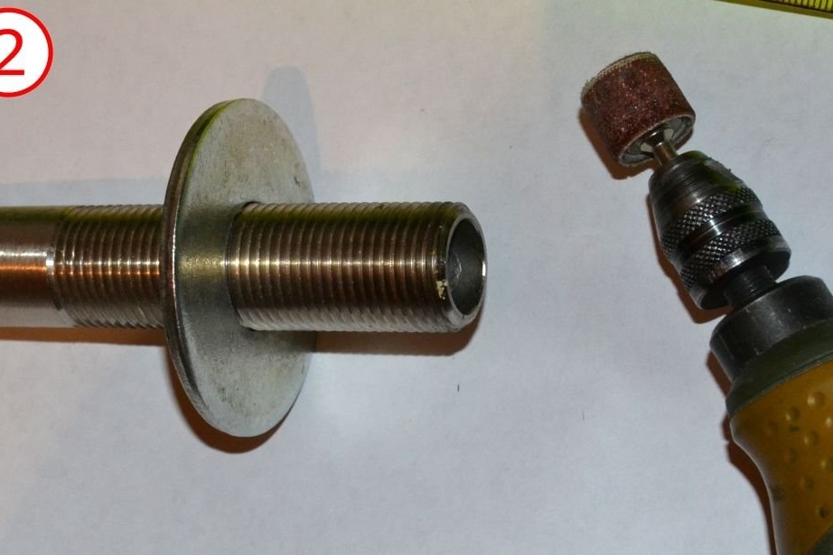
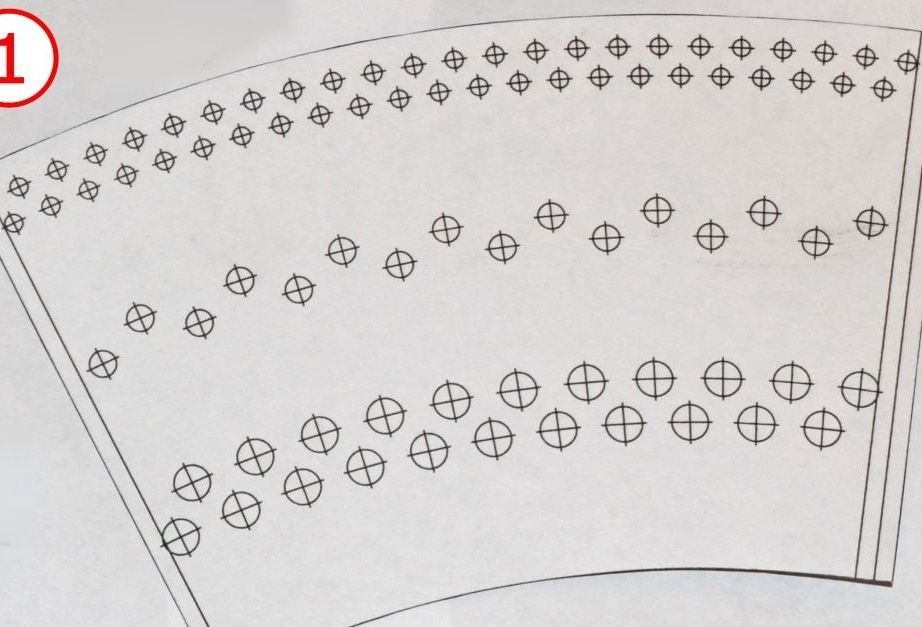
You can cut discs from a metal sheet and then drill a hole in the center, but most likely you will not get into the center. Therefore, drill a hole in the sheet of metal, and then glue the paper template so that the hole in the metal and the place for the hole in the paper template match. Cut metal according to the pattern.
You can find and download the templates below:
turbine wheel pattern
View online file:
turbine blade template
View online file:
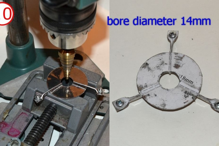
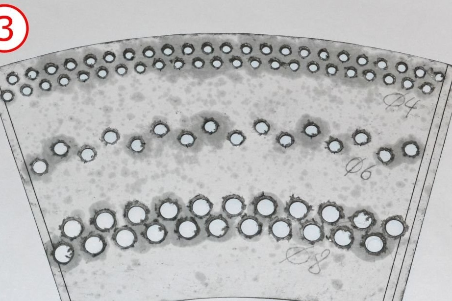
Drill auxiliary holes. (Note that the center holes should already be drilled.Also note that the turbine wheel has only a central hole.)
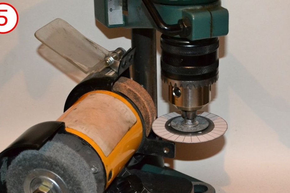
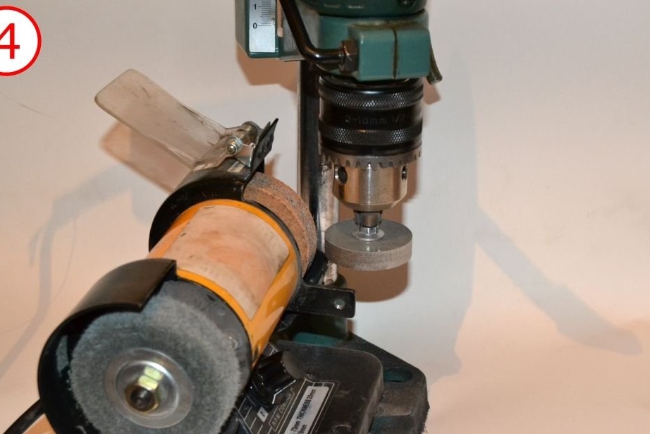
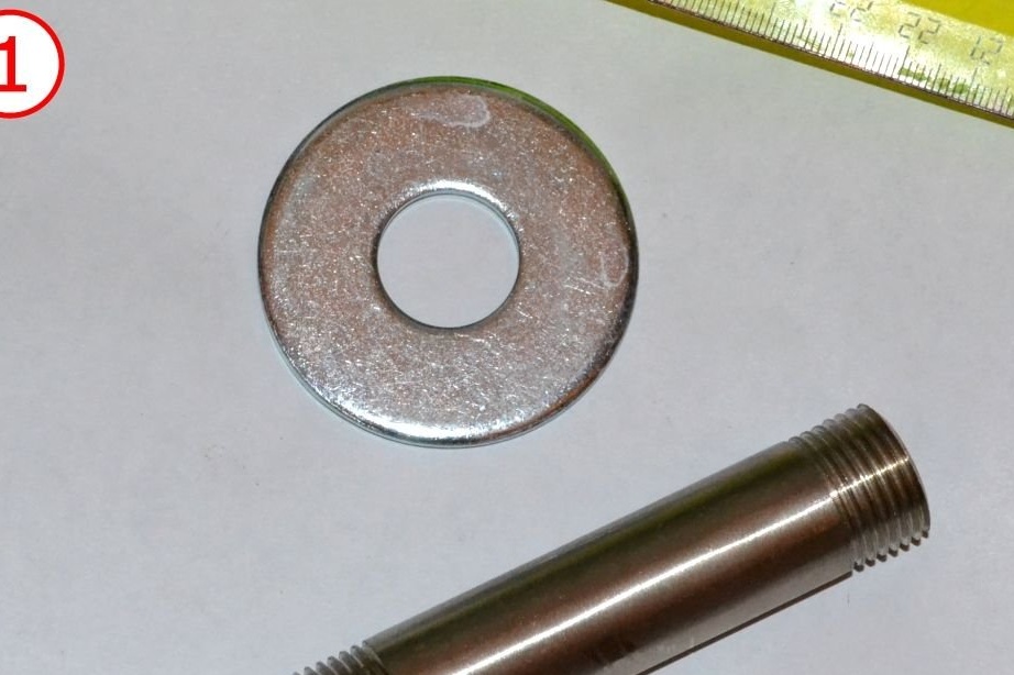
It would also be nice to leave a little allowance when cutting metal, and then grind the edge of the discs using a drilling machine and sharpener.
At this point, it might be better to make several backup disks. Further it will be clear why.
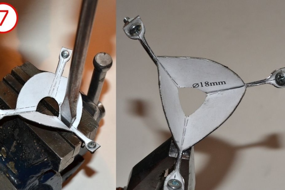
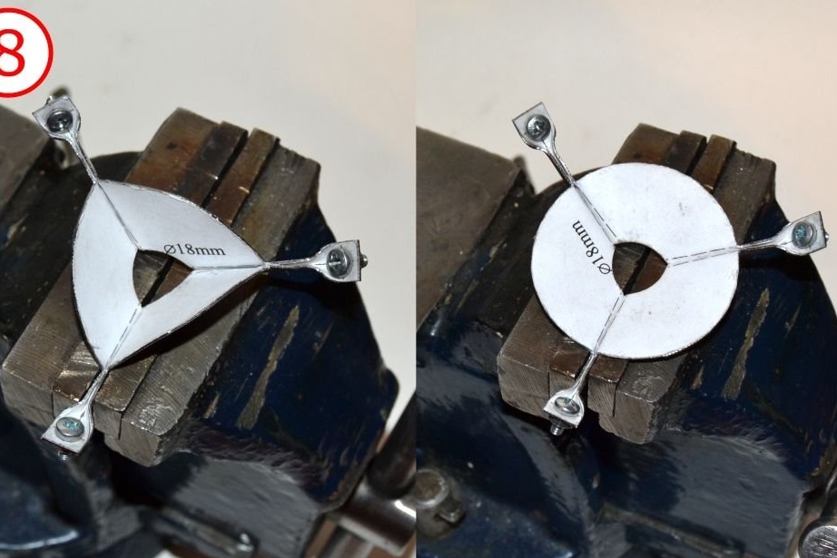
Blade formation
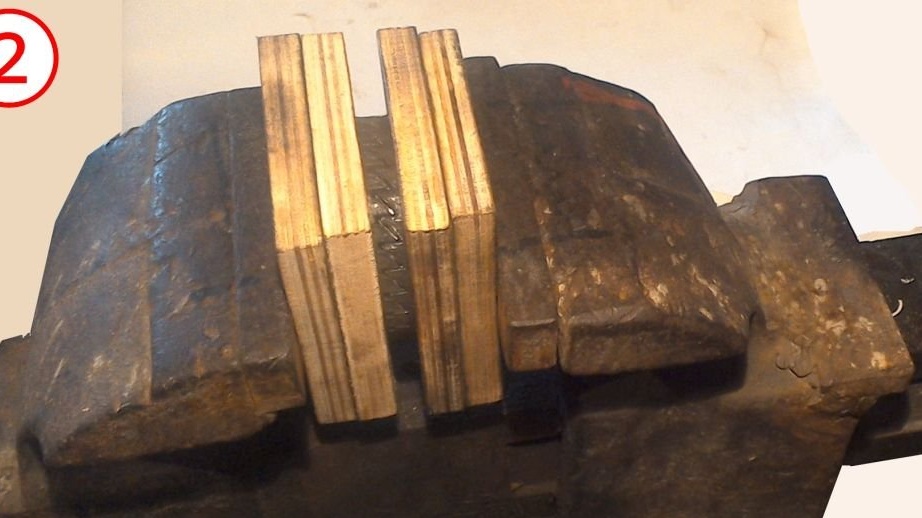
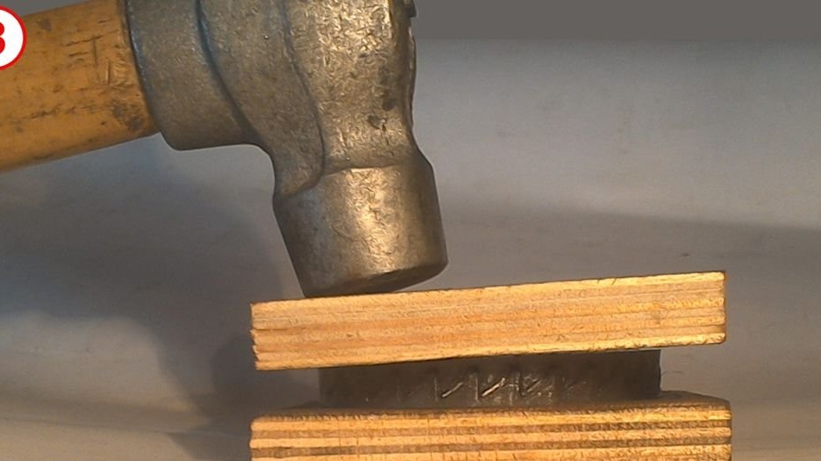
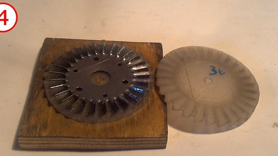
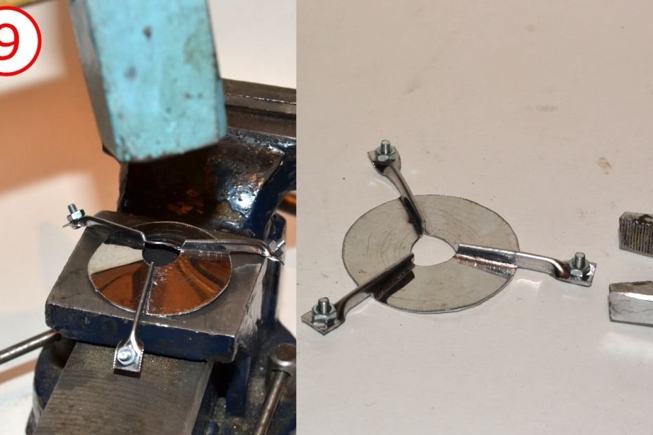
Chopped discs are difficult to fit into the die. Use pliers to rotate the blades slightly. Discs with pre-twisted blades are much easier to form matrices. Grip the disk between the halves of the press and squeeze it into a vice. If the matrices were pre-lubricated with machine oil, everything will go much easier.
The vise is a pretty weak press, so most likely you will need to hit the knot with a hammer to compress it further. Use a few wooden cushions so as not to break the plastic dies.
Two-stage formation (using 1st-pass matrices and 2nd-pass matrices to finalize the form) gives definitely better results.
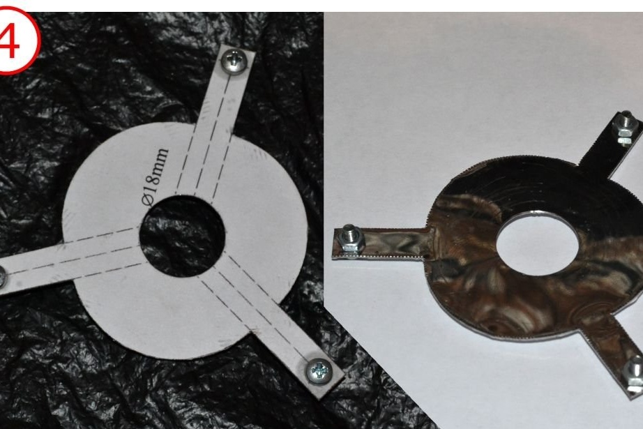
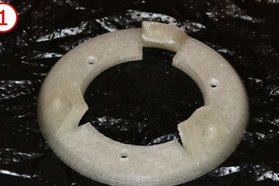
We make a support
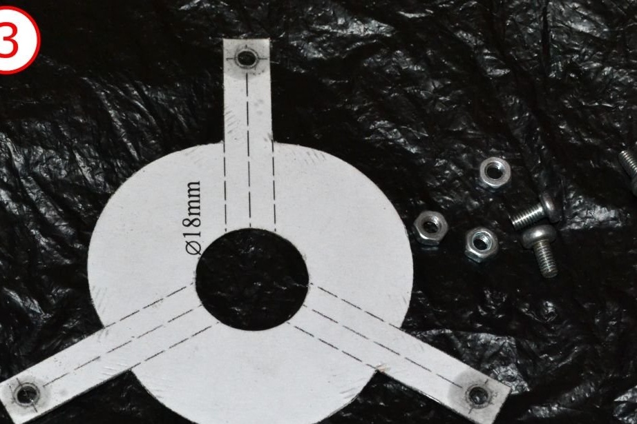
The document file with the template for the support is here:
View online file:
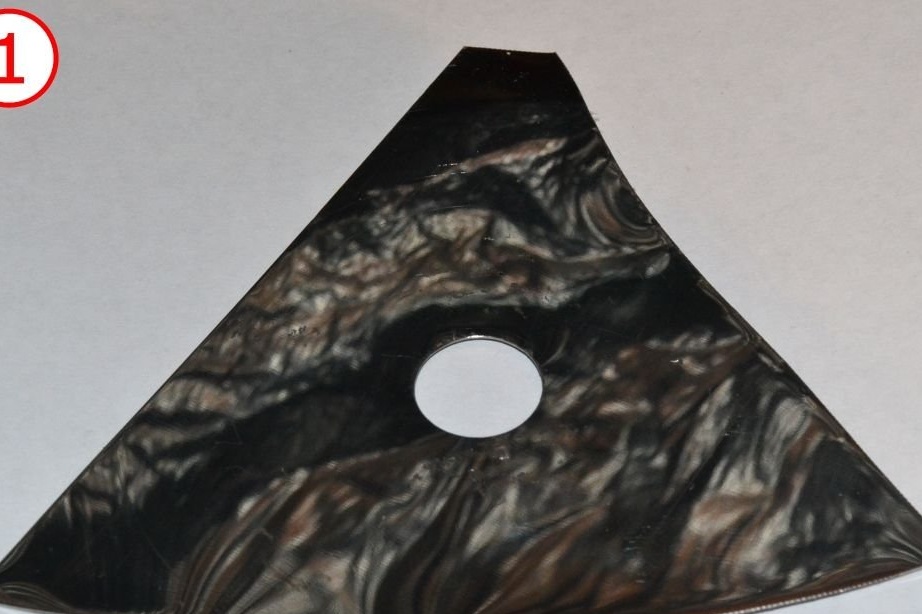
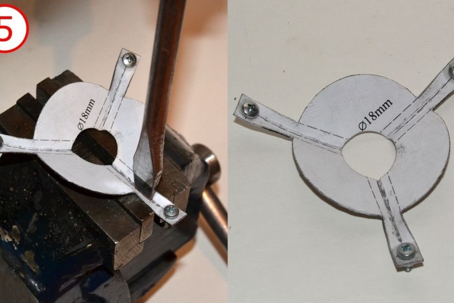
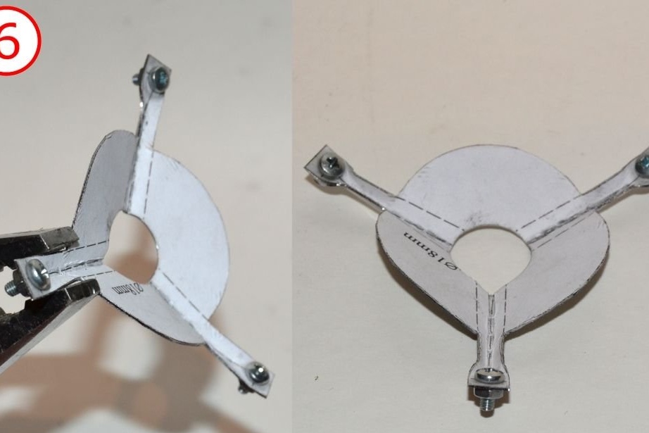
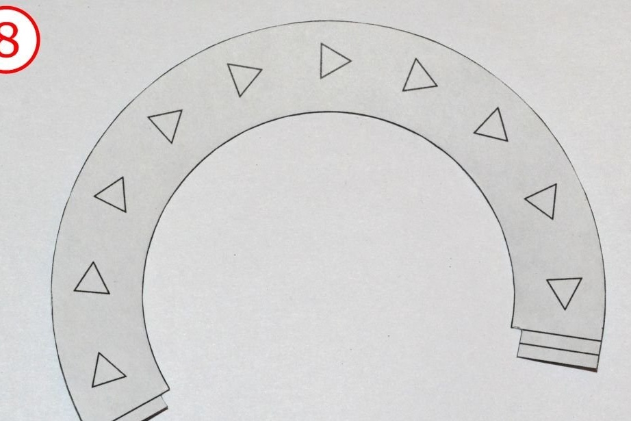
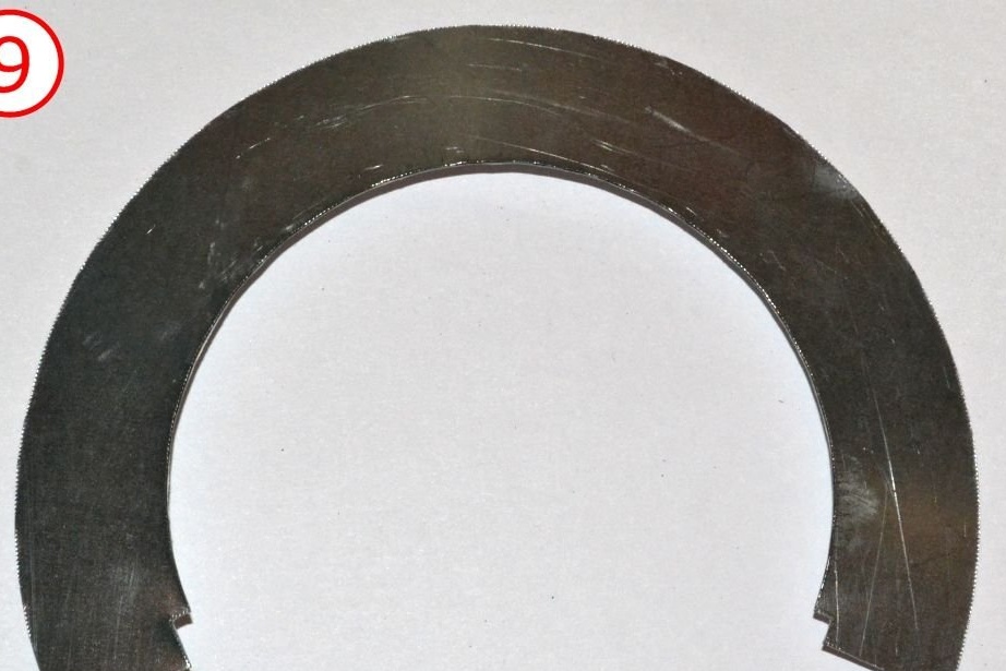
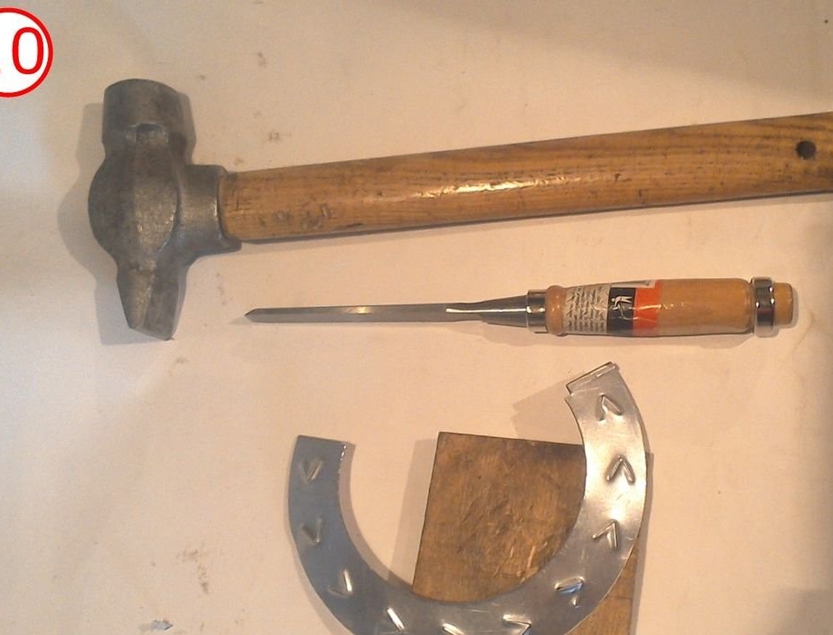
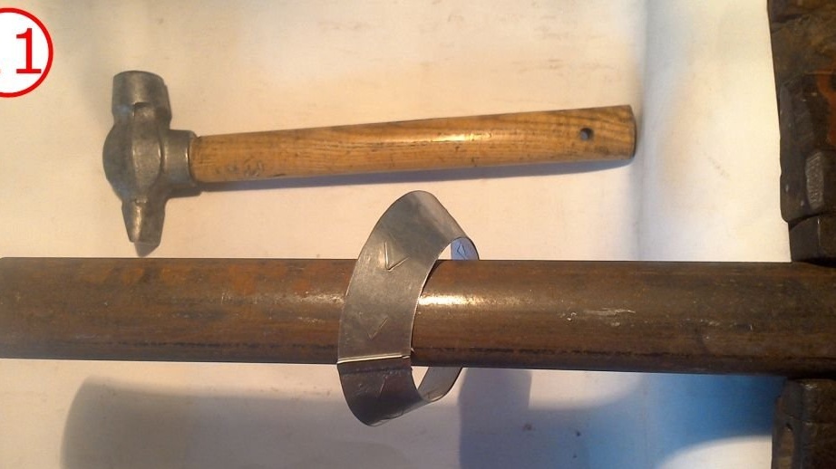
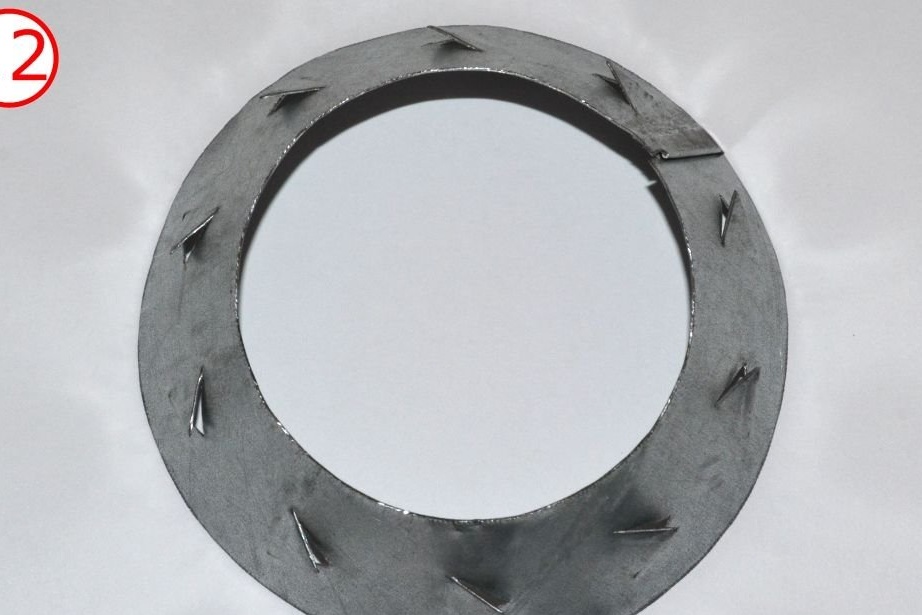
Cut the part from a stainless steel sheet, drill the required holes and bend the part as shown in the photographs.
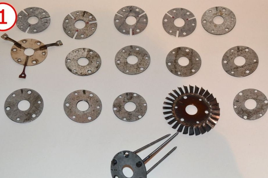
We make a set of metal spacers
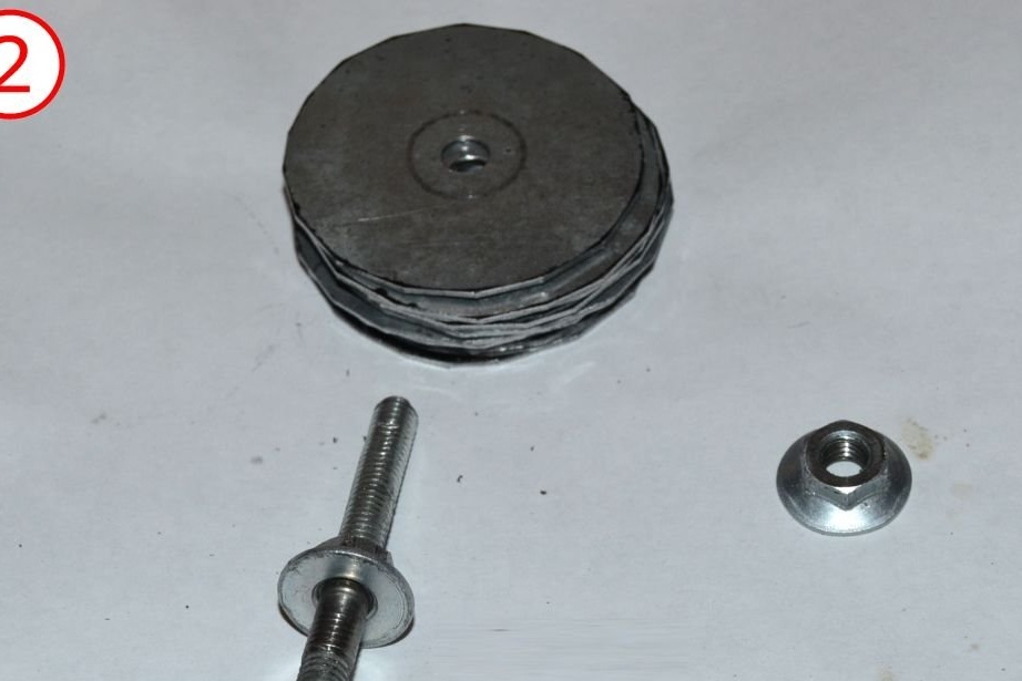
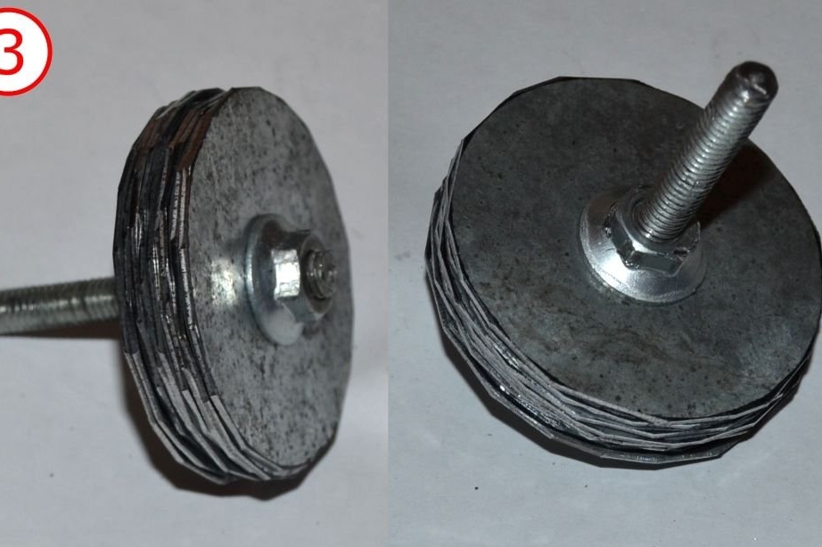
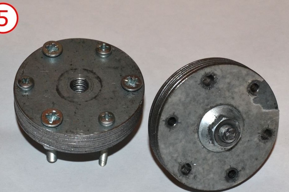
If you have a lathe, you can do all the spacers on it. Another way to do this is to cut out several flat disks from a sheet of metal, lay them on top of one another and tighten them securely with bolts to get a three-dimensional part.
Use here a sheet of mild (or galvanized) steel 1 mm thick.
Documents with templates for spacers are here:
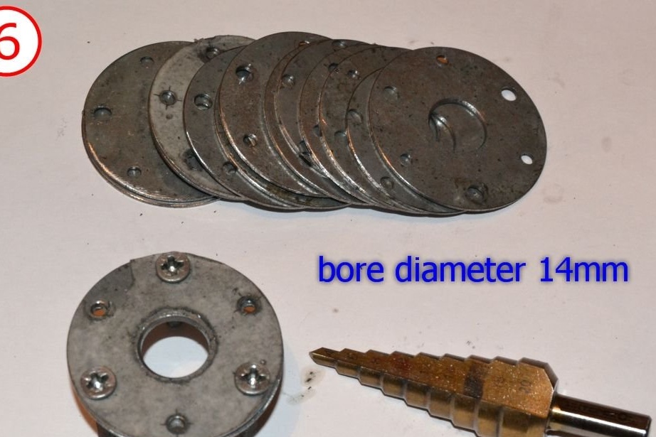
You will need 2 small disks and 12 large ones. The quantity is given for a sheet of metal 1 mm thick. If you are using thinner or thicker, you will need to adjust the number of discs to get the correct overall thickness.
Cut discs and drill holes. Turn the same diameter discs as described above.
Support washer
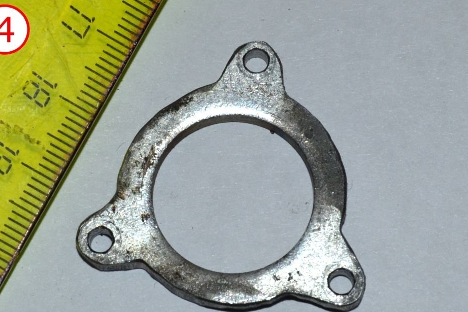
Since the support washer holds the entire NGV assembly, you should use thicker material here. You can use a suitable steel washer or sheet (black) with a thickness of at least 2 mm.
Pattern for a washer:
View online file:
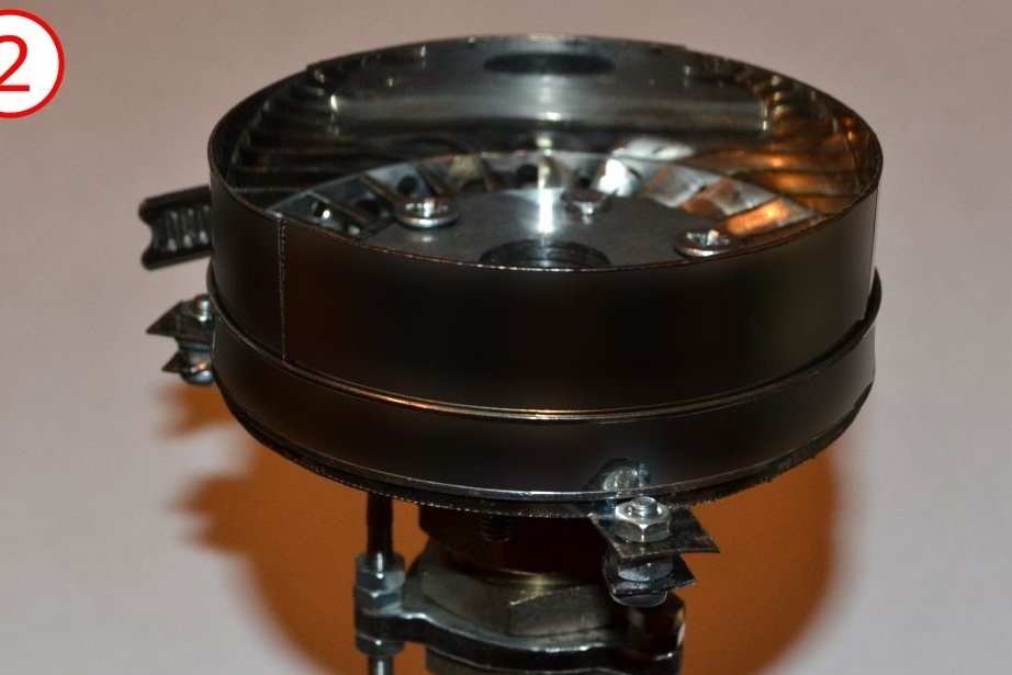
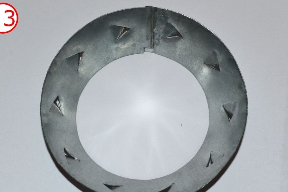
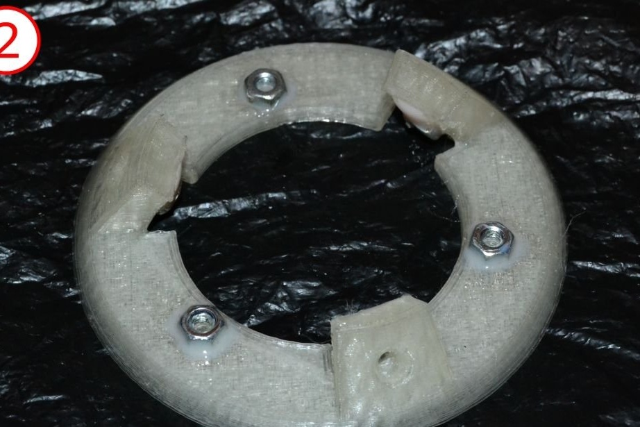
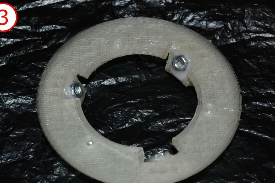
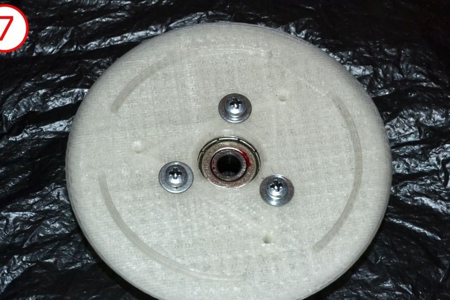
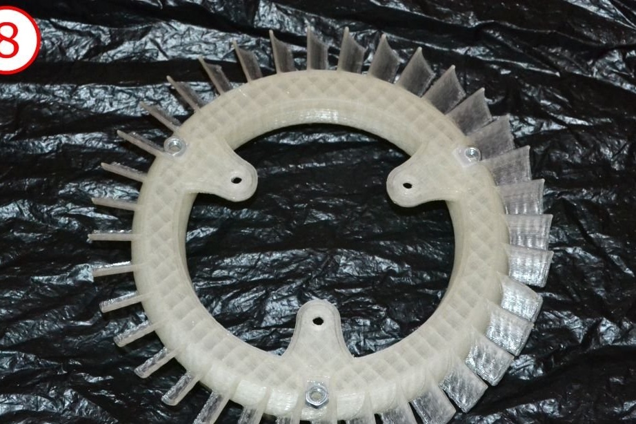
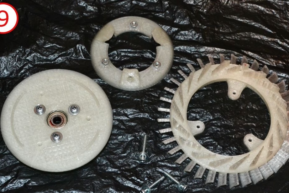
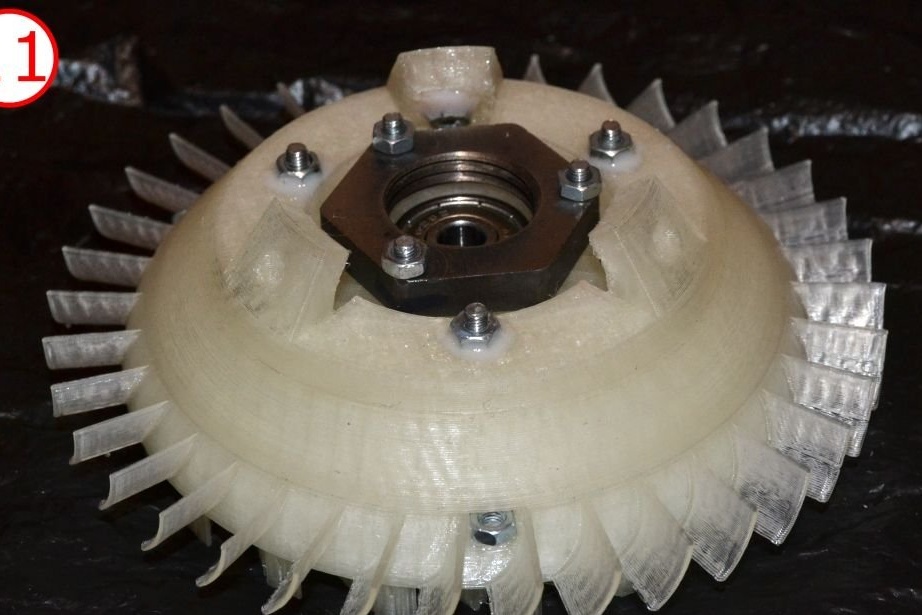
Assembly of the interior of NGV
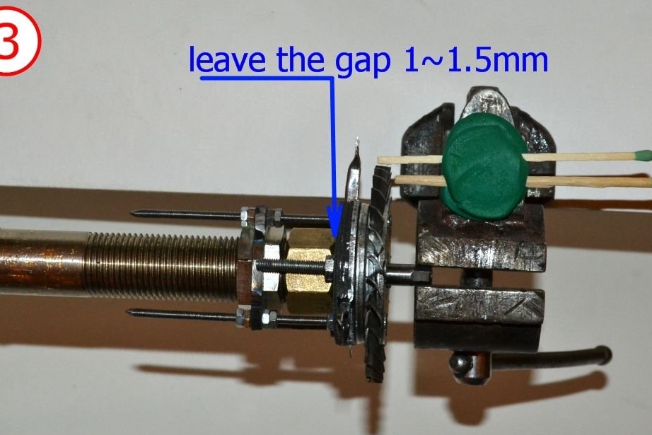
Now you have all the details for assembling NGV. Install them on the hub as shown in the photographs.
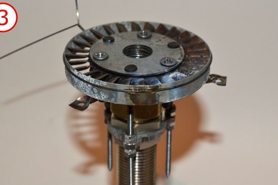
The turbine needs some pressure for normal operation. And in order to prevent the free flow of hot gases, we need the so-called "turbine casing." Otherwise, the gases will lose pressure immediately after passing through the NGV. For proper functioning of the casing must correspond to the turbine + a small gap. Since our turbine wheel and NGV wheel have the same diameter, we need something to provide the necessary clearance. This is something - a spacer for the turbine housing. It is simply a strip of metal that is wrapped around an NGV wheel. The thickness of this sheet determines the amount of clearance. Use 0.5 mm here.
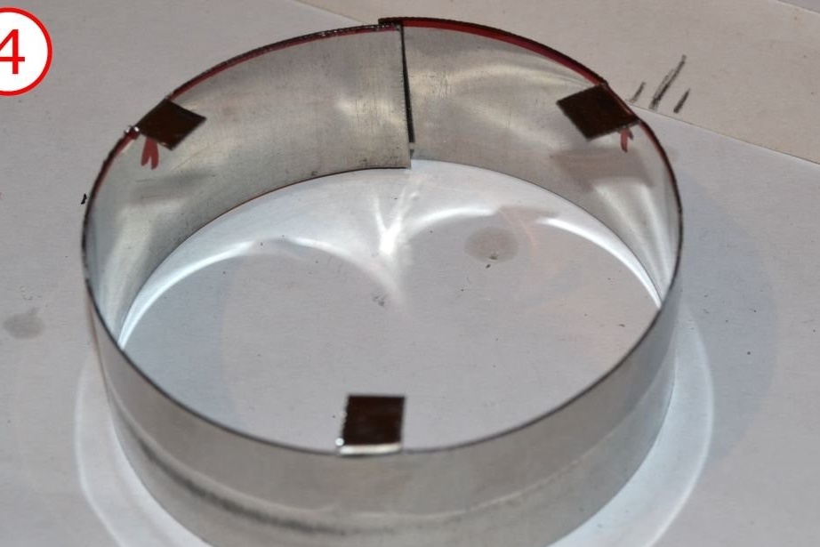
Just cut a strip 10 mm wide and 214 mm long from a sheet of any steel 0.5 mm thick.
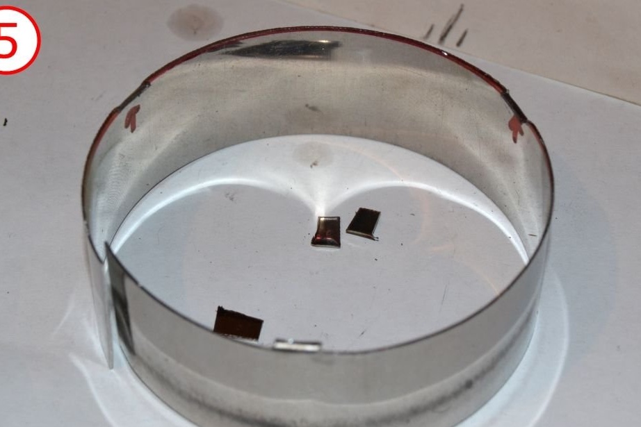
The turbine casing itself will be a piece of metal, along the diameter of the NGV wheel. Or better a couple of pieces. Here you have more freedom to choose the thickness. The casing is not just a strip, as it has attachment ears.
The documentation file with the template for the turbine housing is here:
View online file:
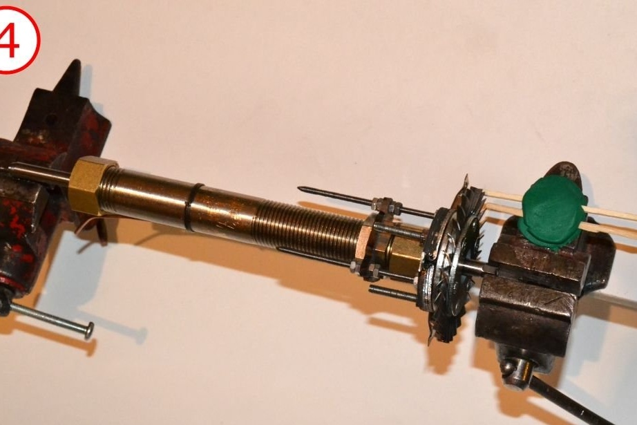
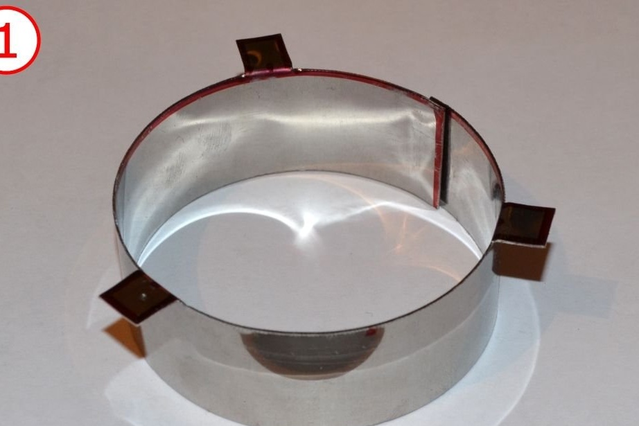
Slip the casing spacer onto the NGV blades. Secure with steel wire. Find a way to fix the spacer so that it does not move when you remove the wire. You can use soldering.
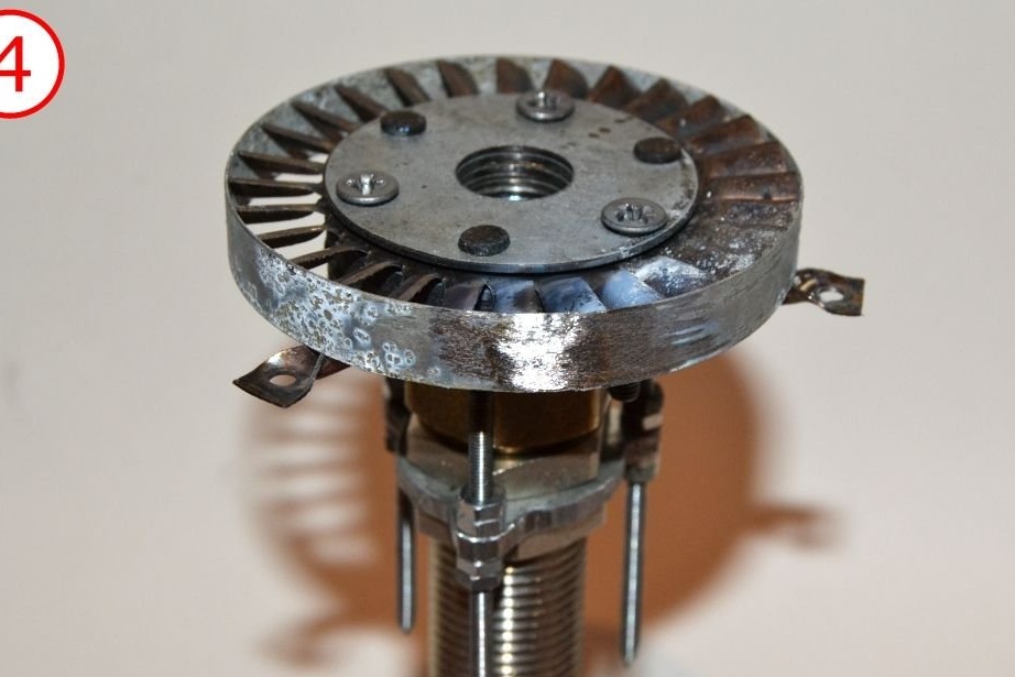
Then remove the wire and wind the turbine shroud onto the spacer. Use wire again to wrap tightly.
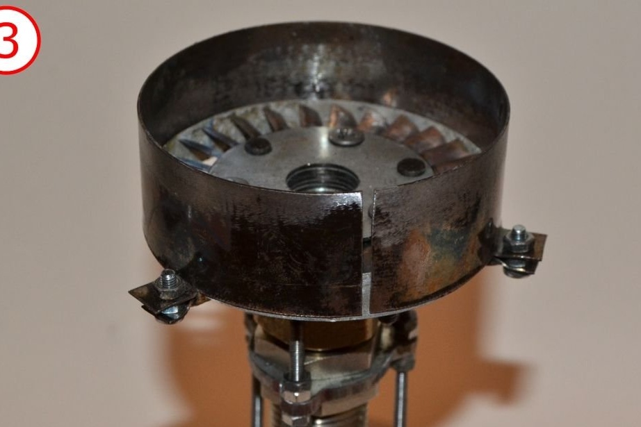
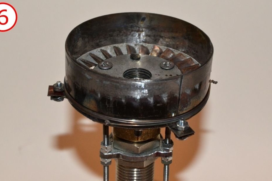
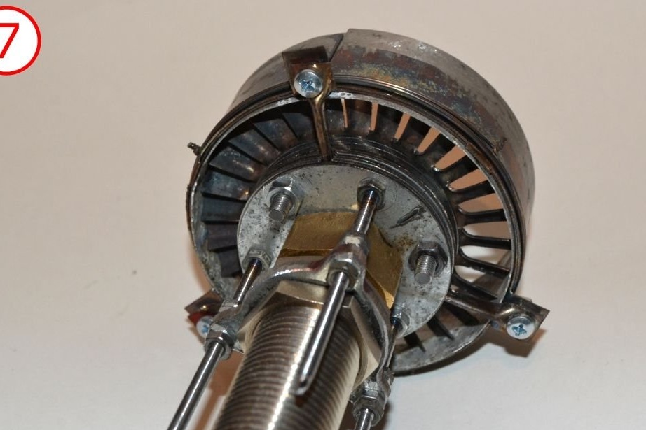
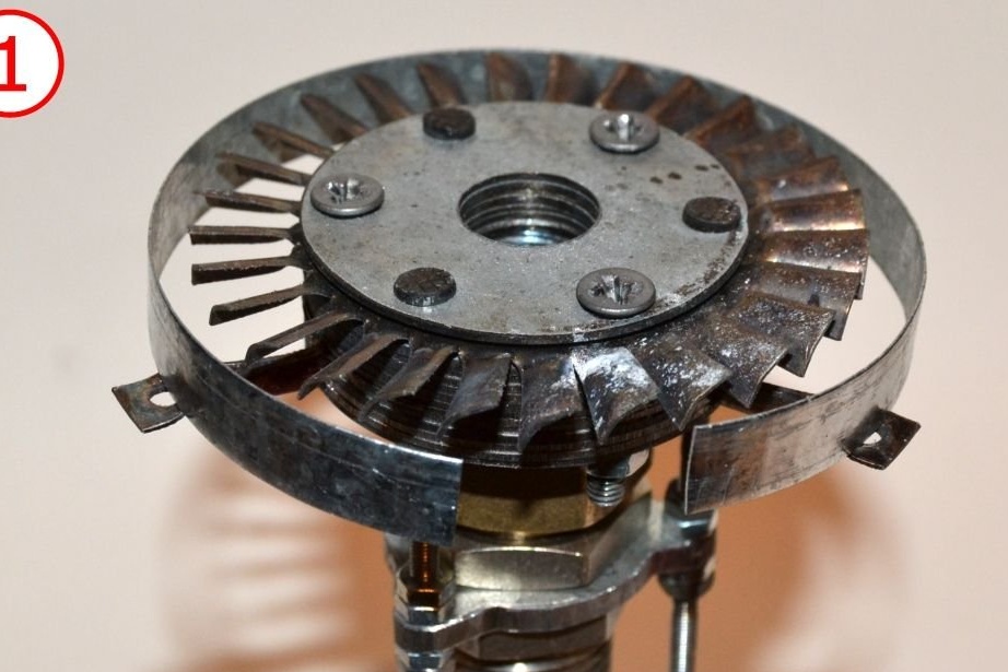
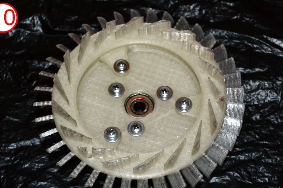
Do as shown in the photos. The only connection between the NGV and the hub are the three M3 screws.This limits the heat flow from the hot NGV to the cold hub and prevents the bearings from overheating.
Check if the turbine can rotate freely. If not, align the NGV casing by changing the position of the adjusting nuts on the three M3 screws. Vary the NGV until the turbine can rotate freely.
Making a combustion chamber
View online file:
Stick this template on top of the metal sheet. Drill holes and cut the mold. There is no need to use stainless steel. Roll up the cone. To ensure that it does not unfold, bend it.
The front of the camera is here:
View online file:
Use this pattern again to make a cone. Use a chisel to make wedge slots, and then twist into a cone. Fasten the cone with a bend. Both parts are held together only by friction of the engine. Therefore, you do not need to think about how to fix them at this stage.
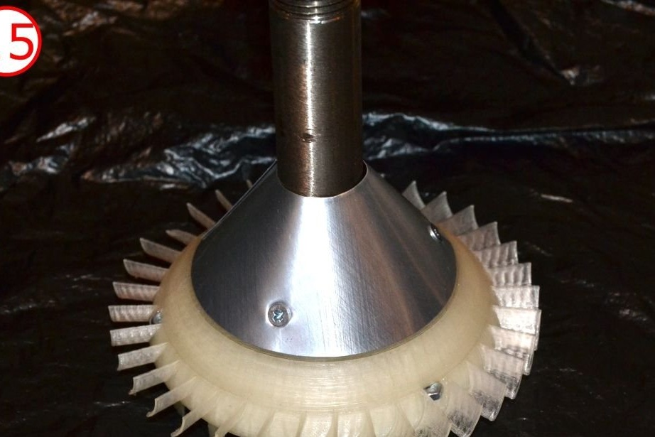
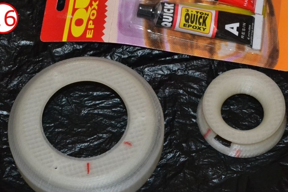
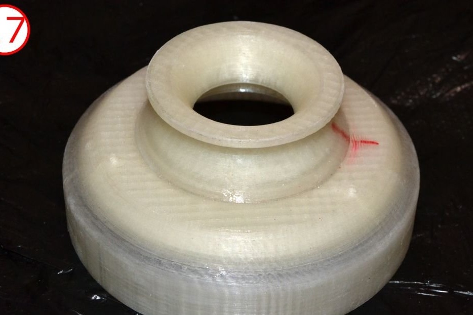
Working wheel
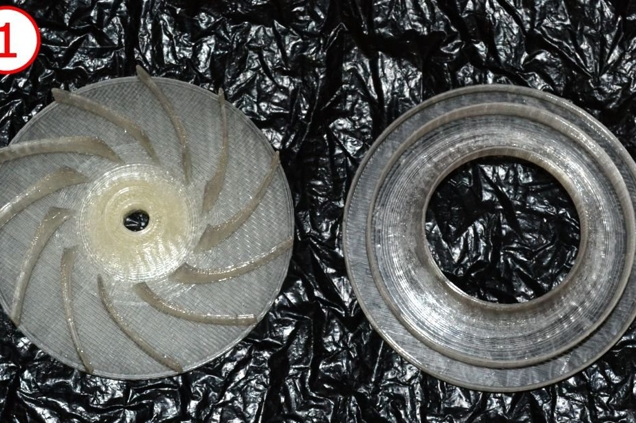
The impeller consists of two parts:
blade disc and casing
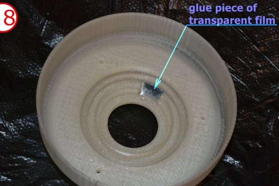
This is Kurt Shrekling's impeller, which has been greatly modified by me to be more tolerant of longitudinal displacements. Pay attention to labyrinth, which prevents the return of air due to back pressure. Print both parts and glue the coating onto the blade disc. Good results can be obtained using acrylic epoxy.
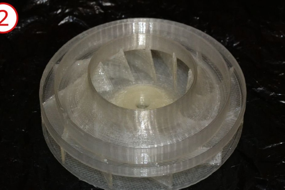
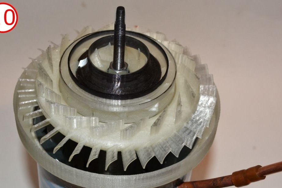
Compressor stator (diffuser)
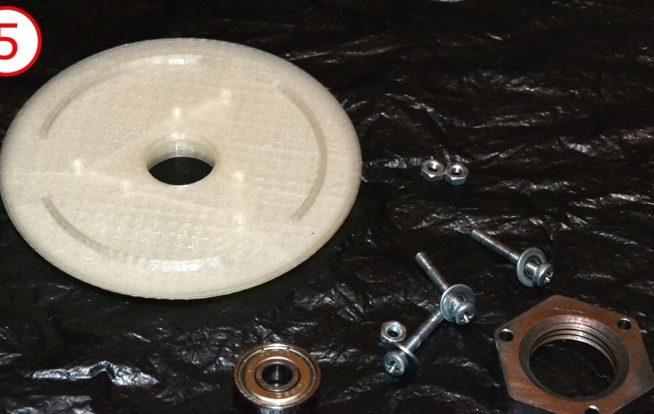
This part is very complex in shape. And when other details can be (at least theoretically) made without the use of precision equipment, this is impossible. Even worse, this part has the greatest effect on compressor efficiency. This means that the fact whether the whole engine will work or not depends heavily on the quality and accuracy of the diffuser. That’s why don’t even try to do it manually. Do it on a printer.
For the convenience of 3D printing, the compressor stator is divided into several parts. Here are the STL files:
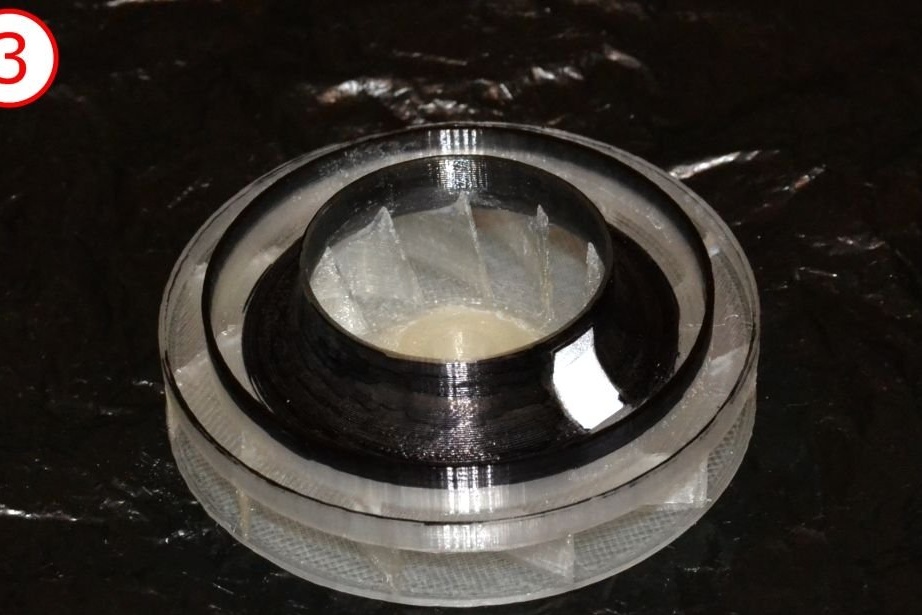
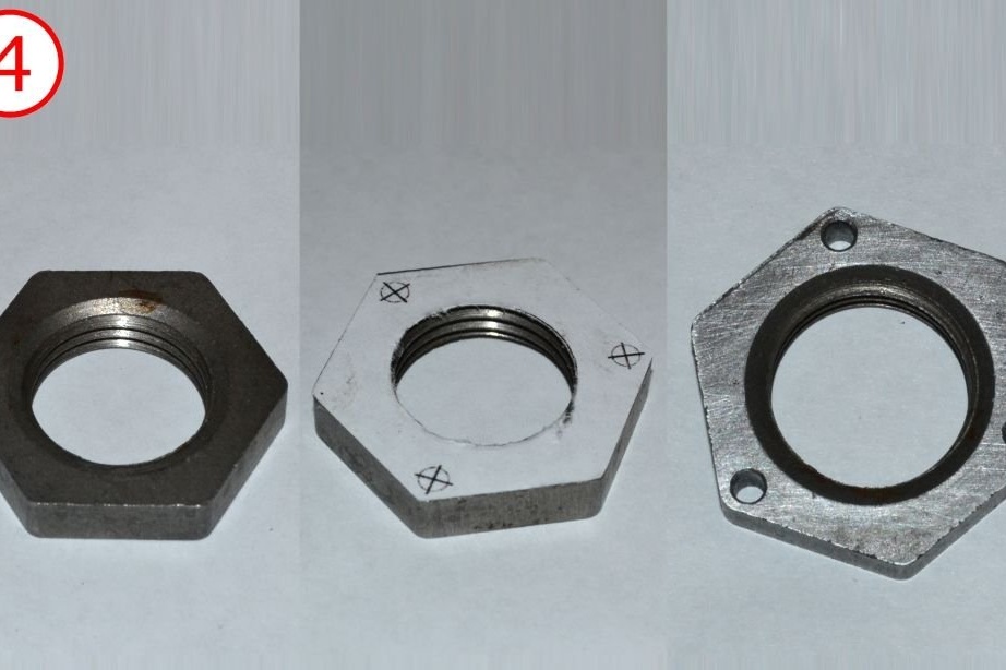
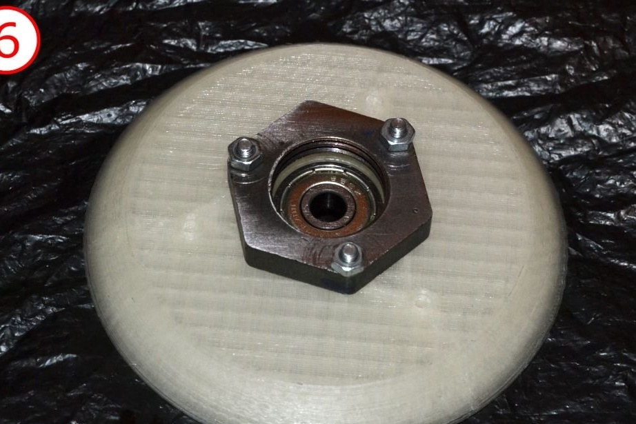
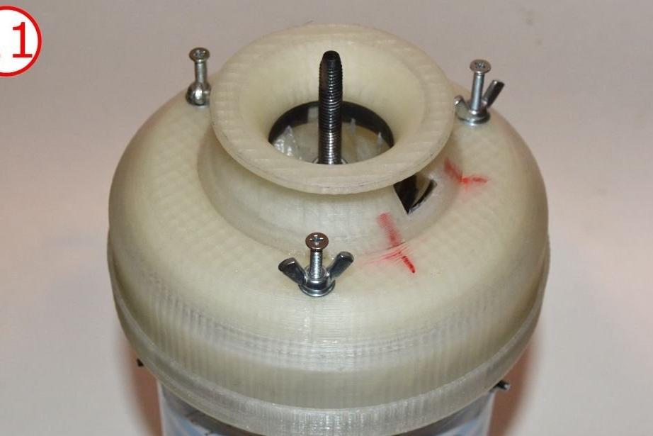
3D print and assemble as shown in the photographs. Please note that a 1/2 "pipe nut must be attached to the central case of the compressor stator. It is used to hold the sleeve in place. The nut is secured with 3 M3 screws.
Template where to drill holes in the nut:
View online file:
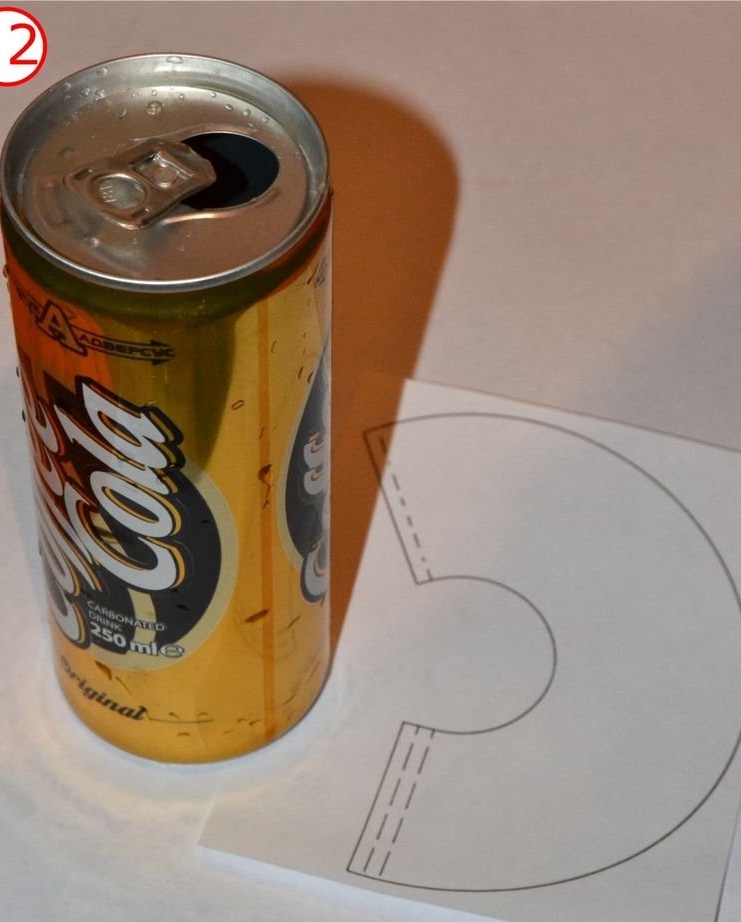
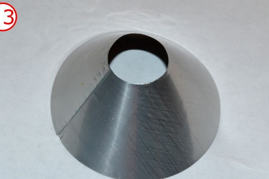
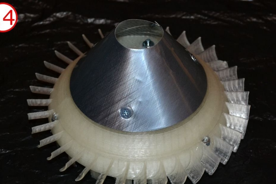
Also pay attention to the heat-shielding cone made of aluminum foil. It is used to prevent softening of PLA parts due to thermal radiation from the combustion liner. You can use any beer can here as a source of aluminum foil.
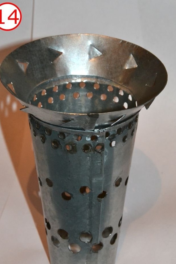
You will need a can with a length of 145 mm and a diameter of 100 mm. Better if you can use a jar with a lid. Otherwise, you will need to install NGV with a hub at the bottom of the can, and you will have additional problems with the assembly of the engine for maintenance.
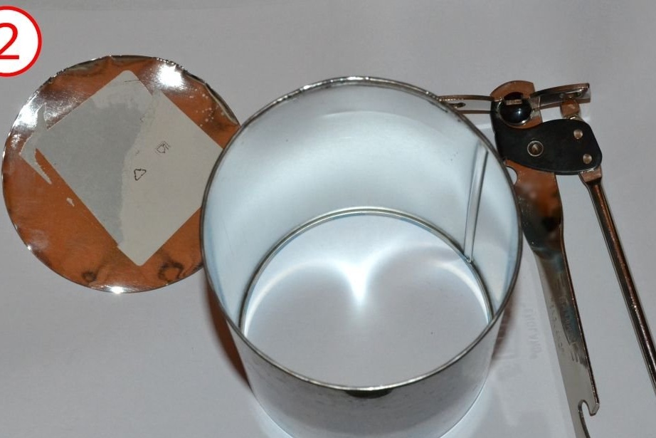
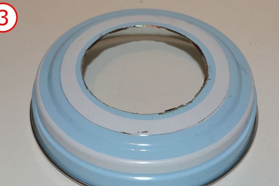
Cut one bottom of the tin can. At the other bottom (or better in the lid), cut a 52 mm round hole. Then cut its edge into sectors, as shown in the photographs.
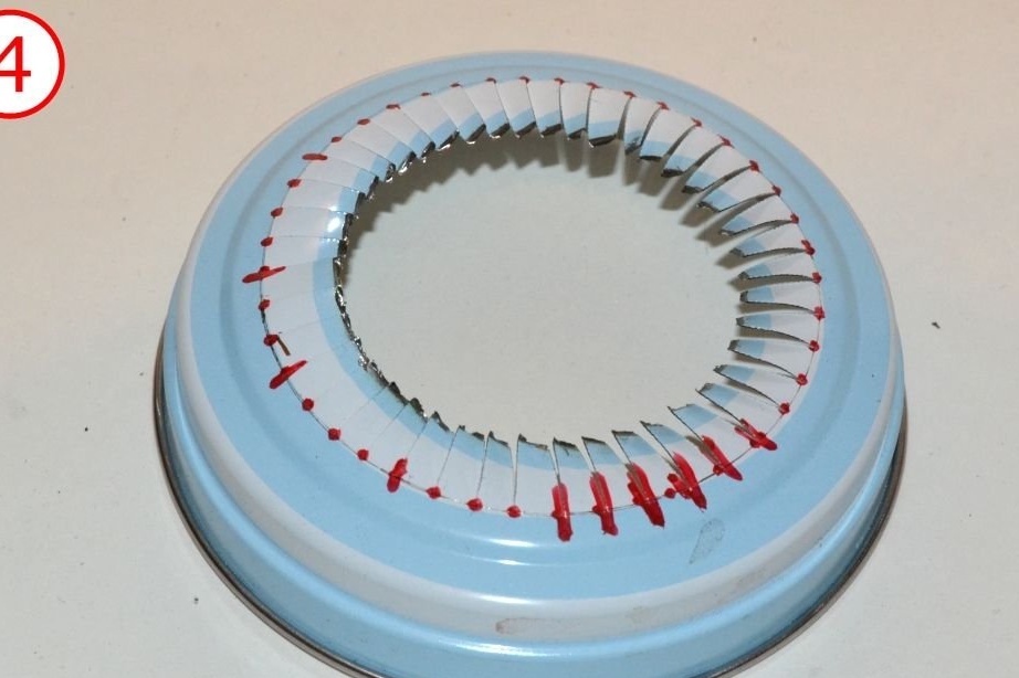
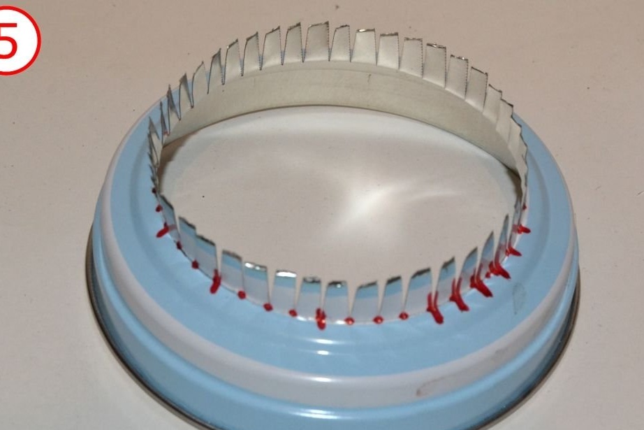
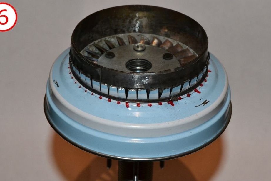
Insert the NGV assembly into the hole. Wrap the sectors tightly with steel wire.
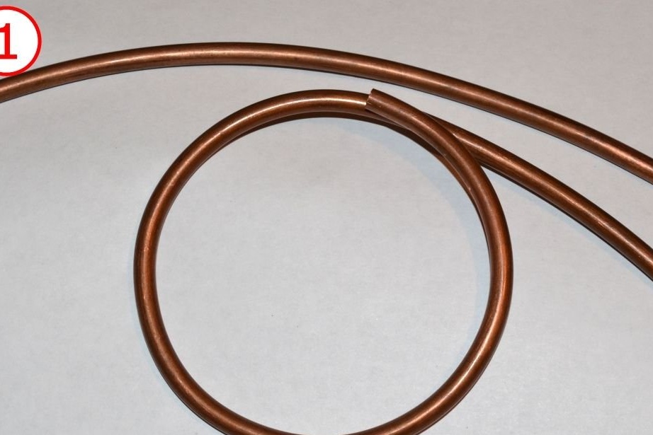
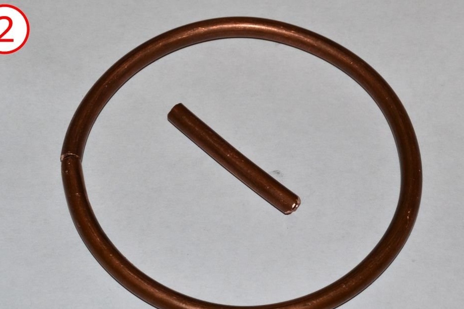
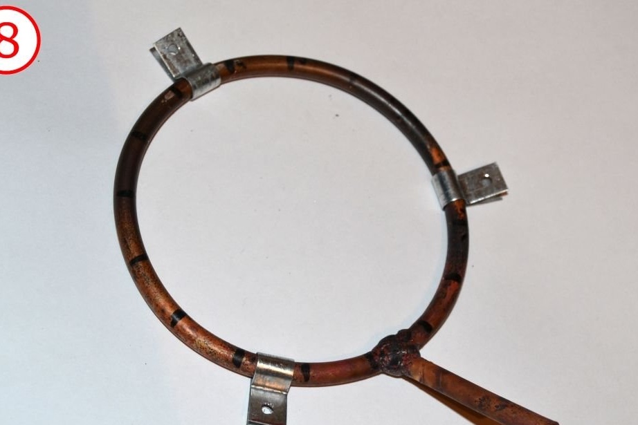
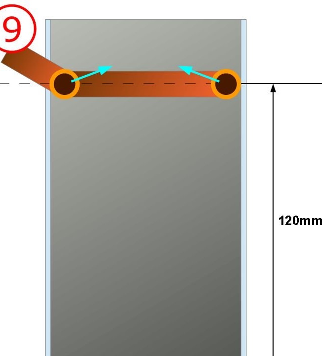
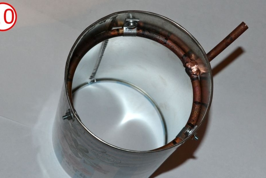
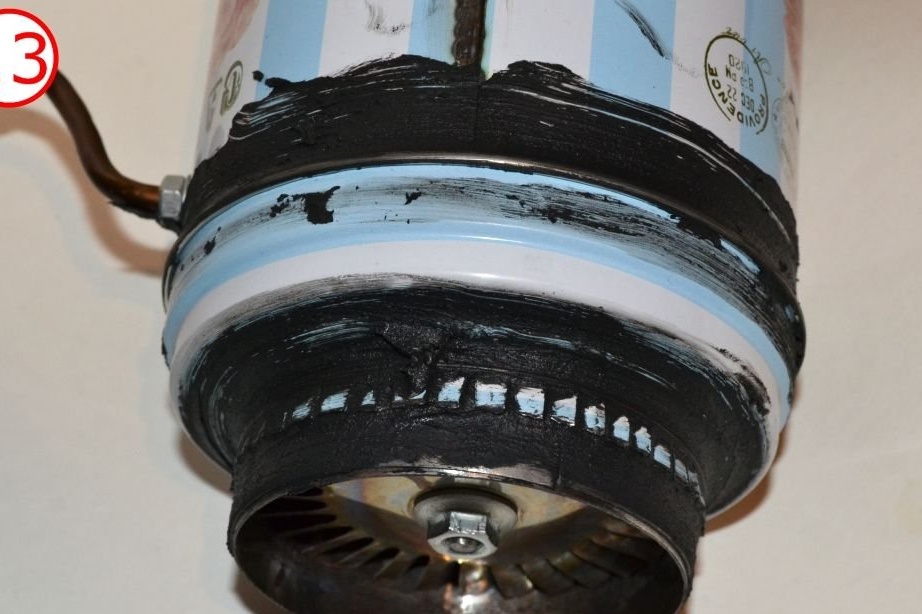
Make a ring from a copper tube (outer diameter 6 mm, inner diameter 3.7 mm). Or better, you can use stainless steel tubes. The fuel ring should fit snugly against the inside of your can. Solder it.
Drill the fuel nozzles. These are just 16 pieces of 0.5 mm holes evenly distributed over the ring. The direction of the holes should be perpendicular to the air flow. Those. you need to drill holes on the inside of the ring.
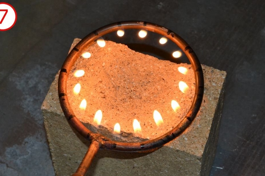
Please note that the presence of so-called "hot spots" in the exhaust of an engine depends almost exclusively on the quality of the fuel ring. Dirty or uneven holes, and in the end you get an engine that simply destroys itself when you try to start it.The presence of hot spots depends much less on the quality of the liner than others are trying to say. But the fuel ring is very important.
Check the quality of the fuel spray by burning it. Tongues of flame should be equal to each other.
When finished, install the fuel nozzle into the can body.
All you have to do at this stage is to put all the pieces together. If things go well, there will be no problem.

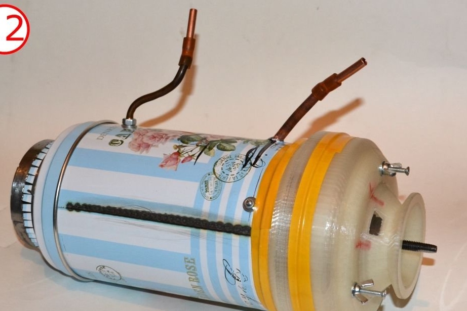
Coat the lid of the can with heat-resistant sealant, you can use silicate glue with heat-resistant filler. You can use graphite dust, steel powder, and so on.
After the engine is assembled, check if its rotor rotates freely. If so, do a preliminary fire test. Use some powerful fan to blow through the air intake or simply rotate the shaft with dremel. Lightly turn on the fuel and light the stream at the rear of the engine. Adjust the rotation to let the flame enter the combustion chamber.
NOTE: at this point you are not trying to start the engine! The sole purpose of a fire test is to heat it and see if it behaves well or not. At this point, you can use a butane bottle, which is commonly used for hand burners. If everything is fine, you can go to the next step. However, it is better to seal the engine with sealant for the furnace (or silicate glue filled with a small amount of heat-resistant powder).
You can start the engine either by blowing air into it, or by rotating its shaft with some kind of starter.
Be prepared to burn several NGV discs (and possibly turbines) when trying to start. (This is why it was recommended that you make several backups in step 4.) Once you are comfortable with the engine, you can start it without any problems at any time.
Please note that at present the engine can serve mainly for educational and recreational purposes. But this is a fully functional turbojet engine that can rotate to any desired speed (including self-destructive ones). Feel free to improve and modify the design to fulfill your goals. First of all, you will need a thicker shaft to achieve higher revs and therefore traction. The second thing to try is to wrap the outer surface of the engine with a metal pipe - a fuel line and use it as an evaporator for liquid fuel. An engine with a hot outer wall is useful here. Another thing to think about is the lubrication system. In the simplest case, this may take the form of a small bottle with a small amount of oil and two pipes - one pipe to relieve pressure from the compressor and direct it to the cylinder, and the other pipe to direct oil from the cylinder under pressure and direct it to the rear beam. Without lubrication, the engine can only run for 1 to 5 minutes depending on the temperature of the NGV (the higher the temperature, the shorter the run time). After that, you need to lubricate the bearings yourself. And with the added lubrication system, the engine can run for a long time.