
A functional generator is not named so because it performs its function well (although if it is assembled qualitatively, it will be so), but because it generates signals corresponding in form to the graphs of various mathematical functions. For example: rectangular, triangular, sinusoidal. The proposed version of such a generator, which was invented by the author of Instructables under the nickname The_Technocrat, works in the sound and ultrasonic ranges. It makes it easy to test and configure audio amplifiers, logic devices, motor drivers, voltage converters, and more. The fastest and most proven way to build a functional generator is to use a specialized chip in it, in this case, type IC8038:
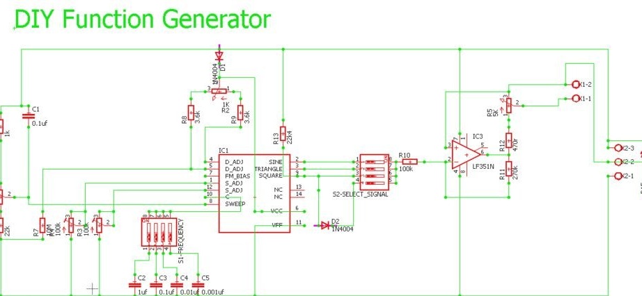
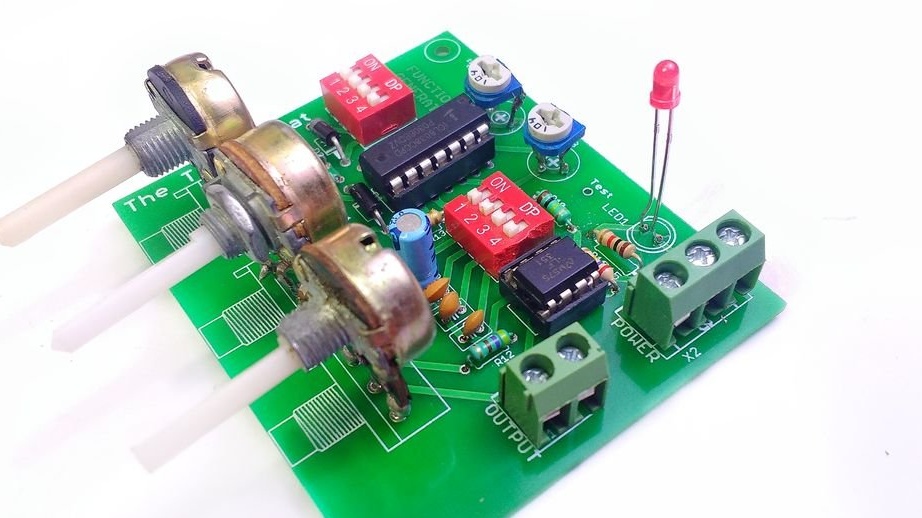
The frequency range of the generator is divided into four sub-bands, the change of which is carried out by switching capacitors. At the three outputs, the microcircuit with the strapping generates three signals of various shapes at once, each of which can be fed to an amplifier located on the same board (LF351N). The fourth mode corresponds to passing rectangular pulses through the diode so that only one half-wave passes - useful when testing devices with digital microcircuits.
The DIP switches chosen by the developer for their purpose are not optimal: if you accidentally select more than one output, they will be closed to each other, and you cannot connect outputs with different levels. This may cause the chip to overheat. It is better to take the dial switches.
Variable resistors are used for smooth adjustments: R1 - frequency, R2 - duty cycle of rectangular pulses (when generating signals of other forms, it must be set in the middle position), R5 - amplitude. Trimmer resistors R3 and R4 reduce distortion to a minimum when generating a sine wave.
The master begins work on the generator by drawing up a circuit board drawing. This is what happened:
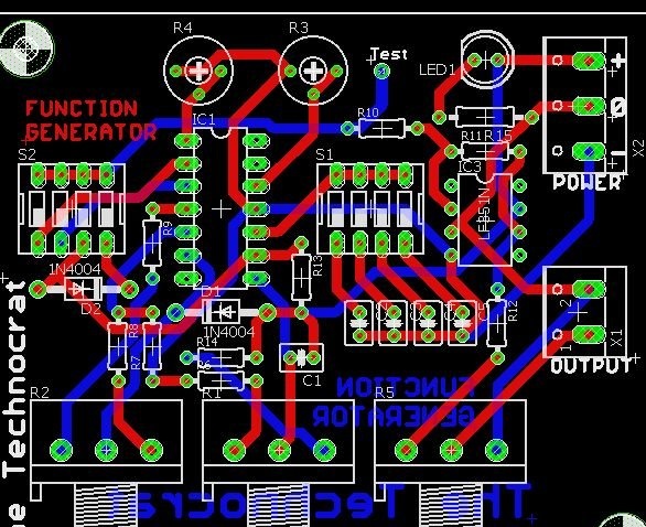
But you can’t make a board for one such picture (it is needed, rather, for reference on the placement of components, if you ordered the board without silk-screen printing), so for those who want to repeat the design, The_Technocrat laid out Gerber files. You can also make a printed circuit board yourself LUTom or build a generator on a breadboard. It all depends on your capabilities and preferences. The developer got this:
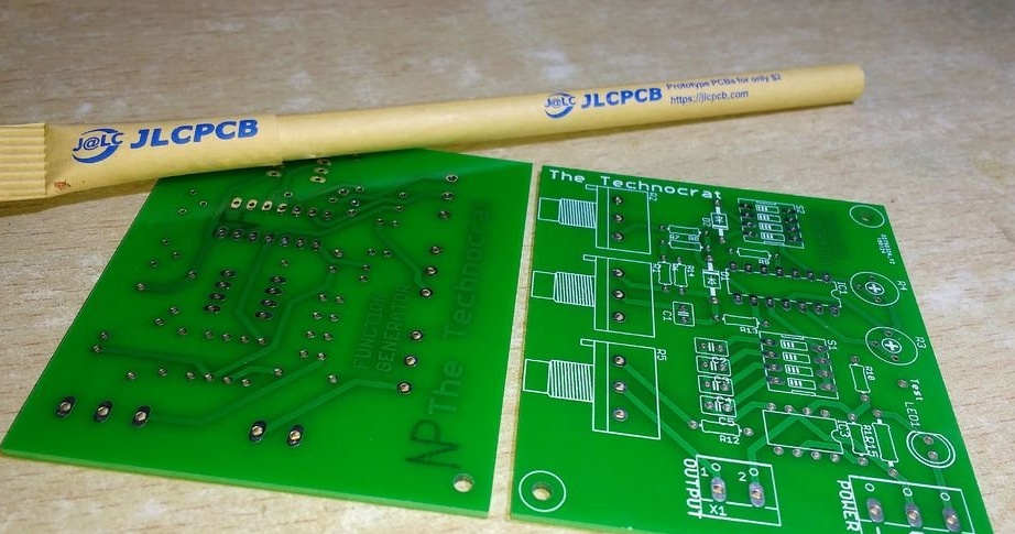
On the board, the master installs all the details according to the prompt on the silk screen or the picture above. Microcircuits, in order to avoid their overheating, it is better to install after the other components.After that, he connects an oscilloscope to the output of the device, and a bipolar 12-volt power supply to the input. Choosing a frequency or amplitude, he first selects the sine wave generation mode in order to adjust the tuning resistors and not touch them anymore. Puts the duty cycle regulator in an intermediate position, but despite this, the screen is not quite a sinusoid:
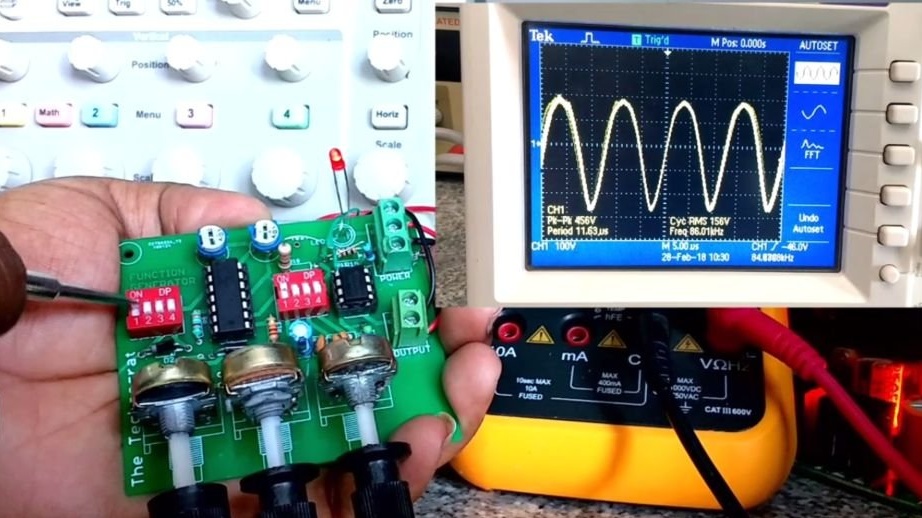
With the help of the already mentioned resistors R3 and R4, he achieves the correct form of the sine wave. The result does not show, but for some reason I believe him. Next in line is the meander:
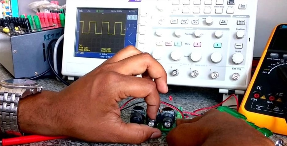
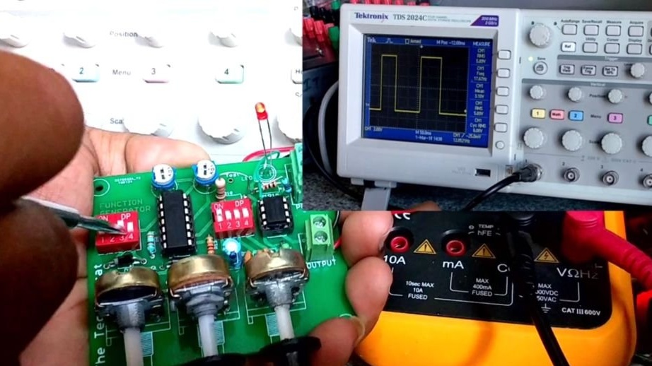
The master rotates the axis of the resistor R2 and receives rectangular pulses of different duty cycle instead of the meander:
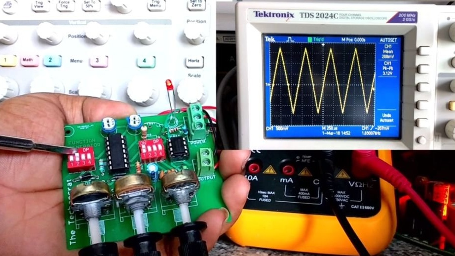
It remains to check the mode of generation of triangular pulses:
Attention: for transistors operating in key mode and not having heat sinks, it is impossible to supply control signals from the generator with any other forms, except for a rectangular one. At the same time, the reliability can be changed and receive PWM.
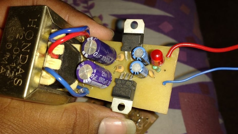
After making sure that the generator is working, The_Technocrat makes a separate bipolar stabilized power supply unit for it (there is no point in bringing the circuit, there are 7812 and 7912 and everything is painfully standard):
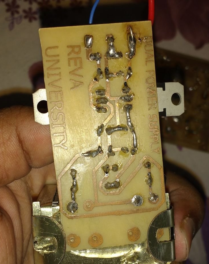
On the back side:
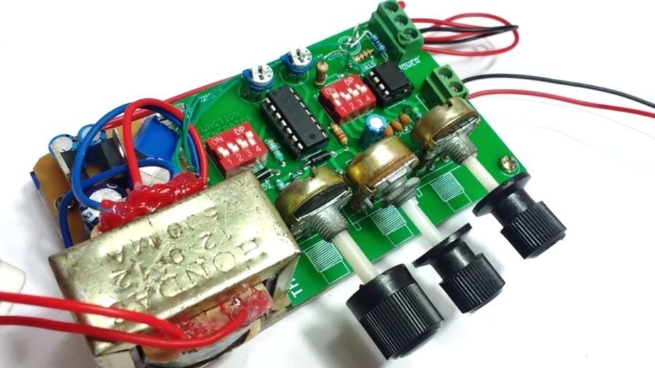
Then he takes a piece of plexiglass and installs the power supply and generator boards on it so that they are always together, like lovebirds:
If the device does not work, the wizard advises you to check which part is to blame: the generator or amplifier. He himself prefers to check in the direction from the output: we look if there is a signal at the output of the amplifier, if not, it moves to the output of the generator, or to the input of the amplifier, which is one and the same. There is no signal there - the generator does not work. There is a problem in the amplifier. Checking in the opposite direction is also possible: we leave the oscilloscope or headphones at the output, and touch the connection points of the generator output with the amplifier input to get a tip. If there was silence before, and now the background has appeared, the matter is in the generator. Nothing has changed - in the amplifier. In both ways, you can also check the connection points in the generator-switch-resistor-amplifier chain. The malfunction is localized, and it is clear that the correct assembly of which node (and the correctness of which chip) must be checked.