
Today we do it yourself we will collect the clock on gas discharge indicators, as simple and affordable as possible.
The author of this homemade product is AlexGyver, the author of the YouTube channel of the same name.
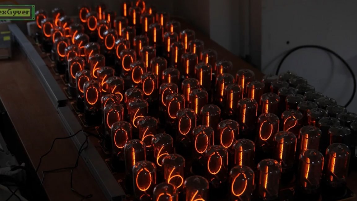
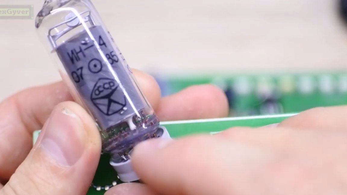
Currently, most gas-discharge indicators are no longer being produced, and the remains of Soviet indicators can only be found in a flea market or radio market. It is very difficult to find them in stores. But the smaller these indicators become, the more interest in them grows. It grows among lovers of lamp, vintage and of course the post of the apocalypse.
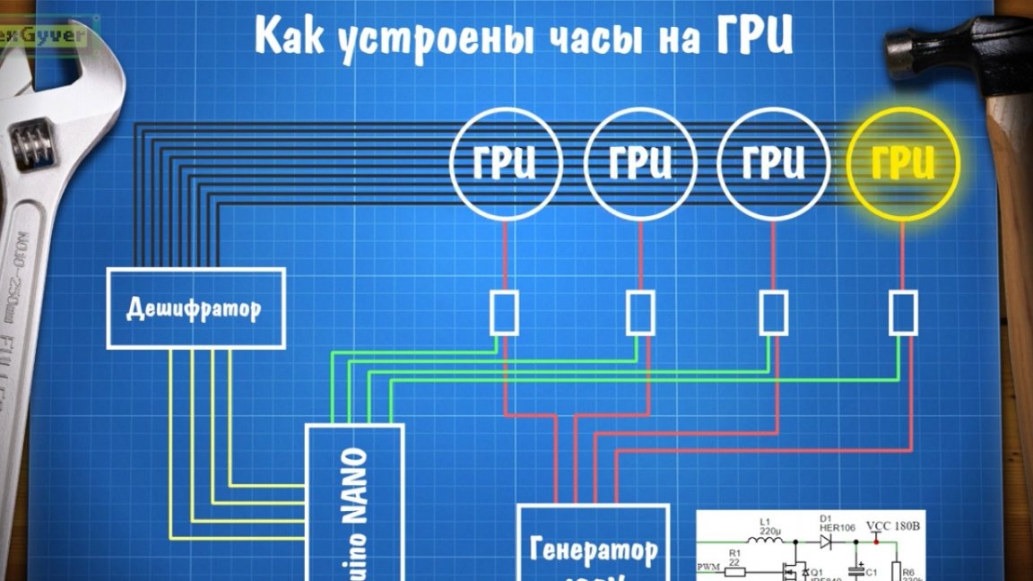
So, we want to make a clock based on them, and for the sake of simplicity and maximum accessibility, we will control the indicators using a microcontroller in the face of the arduino platform, which connects to the computer via USB and the firmware is loaded into it by clicking the mouse. Between arduino and indicators we need some more electronics, which will give out signals along the legs of the indicators. So, firstly, we need a generator that will create a high voltage to power the indicators.
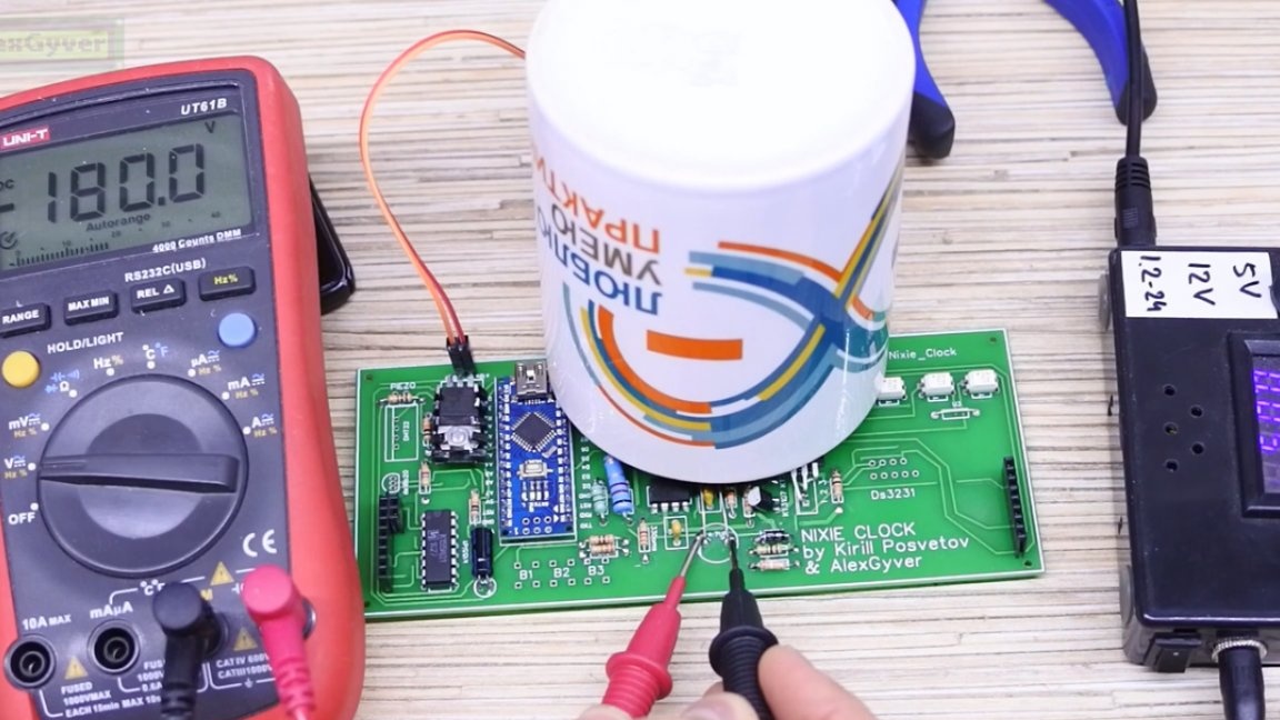
The watch operates on a constant voltage of about 180V. This generator is very simple and operates on inductive emissions. The generator frequency is set by the PWM controller; at a frequency of 16 kHz, the output voltage is 180V. But despite the high voltage, the generator is very, very weak, so do not even think about its other applications, it is only capable of a glow discharge in an inert gas. This voltage, namely +, is sent to the indicators through high-voltage optocouplers. The optocouplers themselves are controlled by an arduino, that is, it can supply + 180V to any indicator. In order for the figure in the indicator to light up, you need to apply land to it, and this is done by the high-voltage decoder - the Soviet microcircuit. The decoder is also controlled by arduino and can connect any digit to the ground.
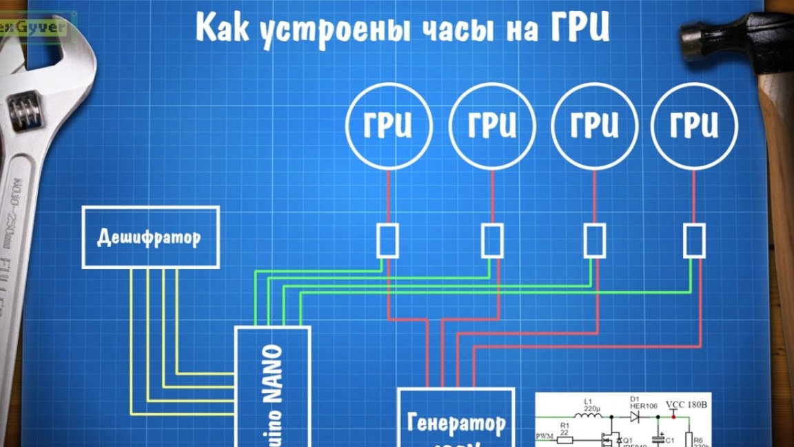
And now attention: we have 6 indicators, and the decoder 1. How does it work? In fact, the decoder is connected immediately to all indicators, that is, to all their digits, and the operation of the decoder and optocouplers is synchronized in such a way that at one time the voltage is applied to only one digit of one indicator, that is, the optocoupler switches the indicators very quickly, and the decoder lights the numbers on them, and it seems to us that all the numbers are lit at the same time.In fact, each digit burns a little more than 2 milliseconds, then another one immediately turns on, the total refresh rate of 6 indicators is about 60 Hz, that is, frames per second, and given the inertness of the process, the eye does not notice any flicker. Such a system is called dynamic indication and can greatly simplify the circuit.
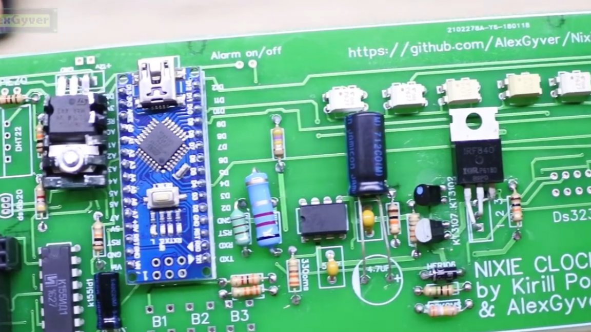
In general, the clock circuit turns out to be very, very complicated, so it is reasonable to make a printed circuit board for it.
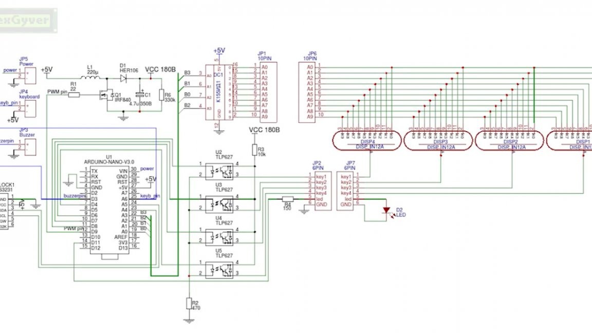
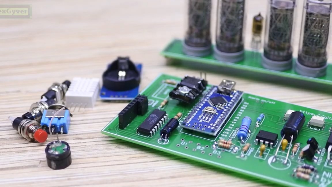
The board is universal for IN12 and IN14 indicators. On this board, in addition to everything necessary for the strapping indicators, there are places for the following glands: an on / off button for an alarm, an alarm beep, thermometer + hygrometer DHT22, a DS18b20 thermometer, a real-time module on a DS3231 chip and 3 buttons for controlling the clock.
All of the listed hardware is optional, and you can connect it, or you can not connect it, all this is configured in the firmware. That is, on this board you can make just a clock, without any buttons and without everything, but you can make a clock with an alarm clock, display of temperature and humidity, this is such a universal board. Naturally, they decided to order a seal from the Chinese, because there are so many thin tracks and transitions to the other side of the board. You will find the so-called gerber board file in the archive, which can be downloaded to.
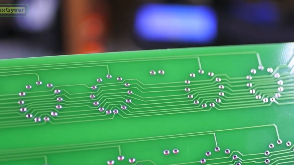
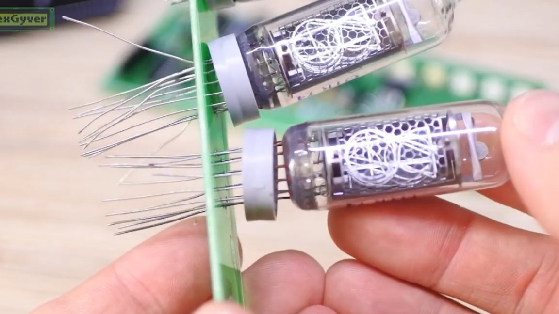
There are many tracks in this project, especially thin ones on the board with indicators.
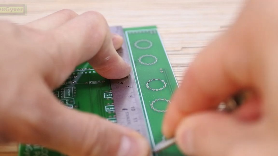
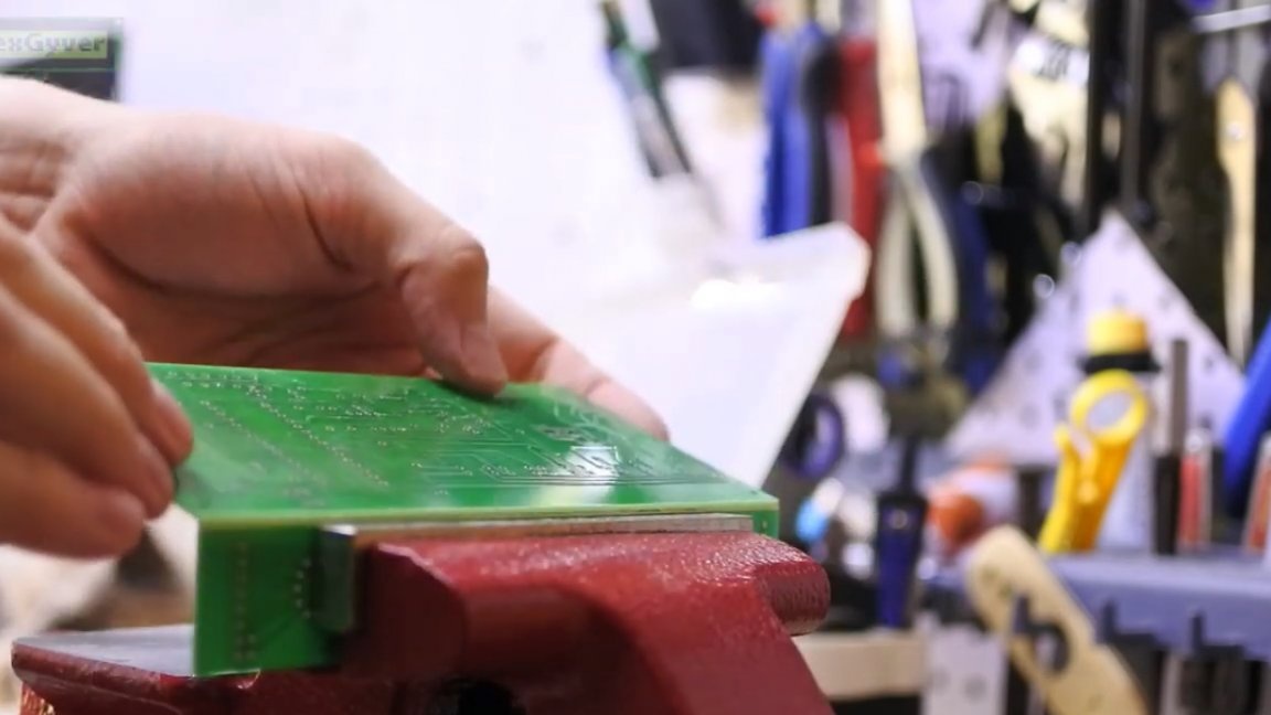
The board needs to be cut into pieces, as it is two-story. But it’s better not to cut, glass dust is very harmful to the lungs. With a hardened self-tapping screw, we scratch the board and gently break it in a vice.
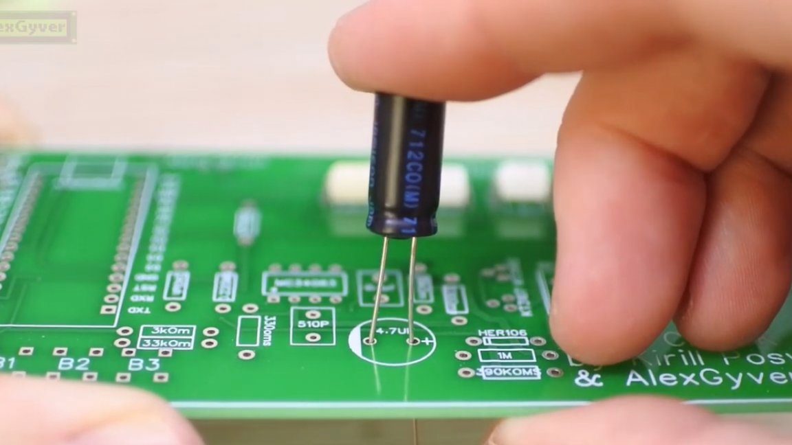
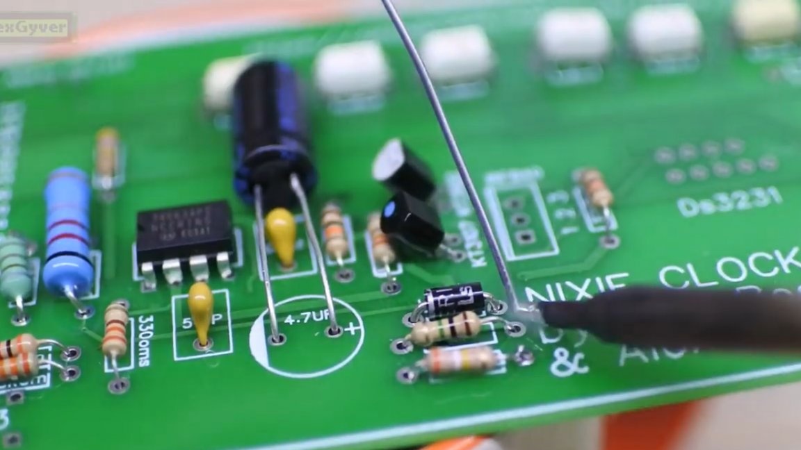
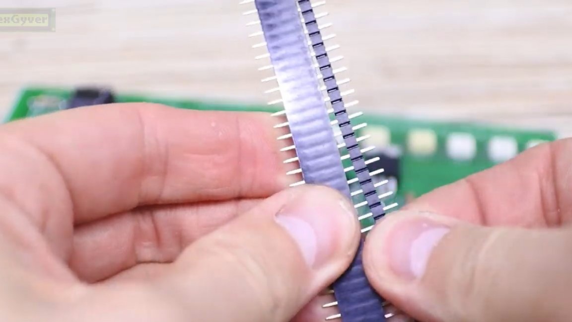
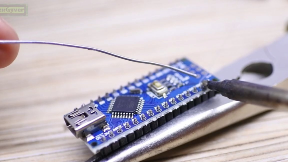
In general, now you need to solder all the components on the board according to the signatures and drawings on the silk screen. You will also need to buy a rack with pins to connect parts of the board.
The project uses full-size Arduino Nano. This is done to simplify the download of firmware even for the most beginners.
So, we collected the bottom board. First you need to test the operation of the generator. If it is not assembled correctly, the capacitor may sag. So we cover it with something and turn on the power.
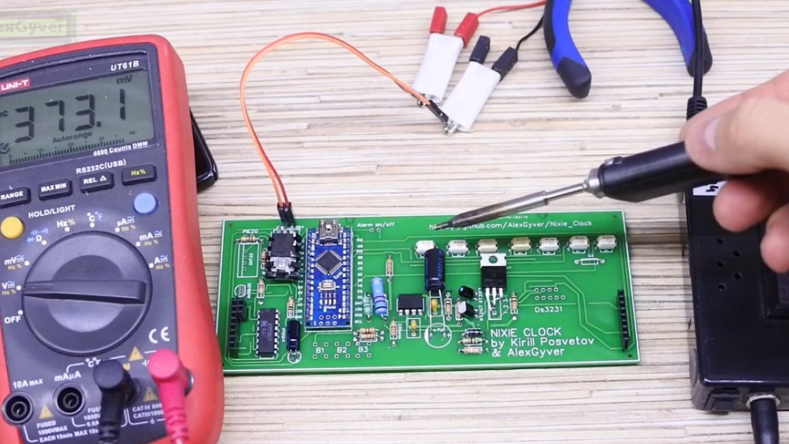
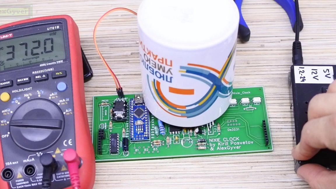
Nothing banged, that's good. Carefully measure the voltage on the legs of the capacitor, should be 180V.
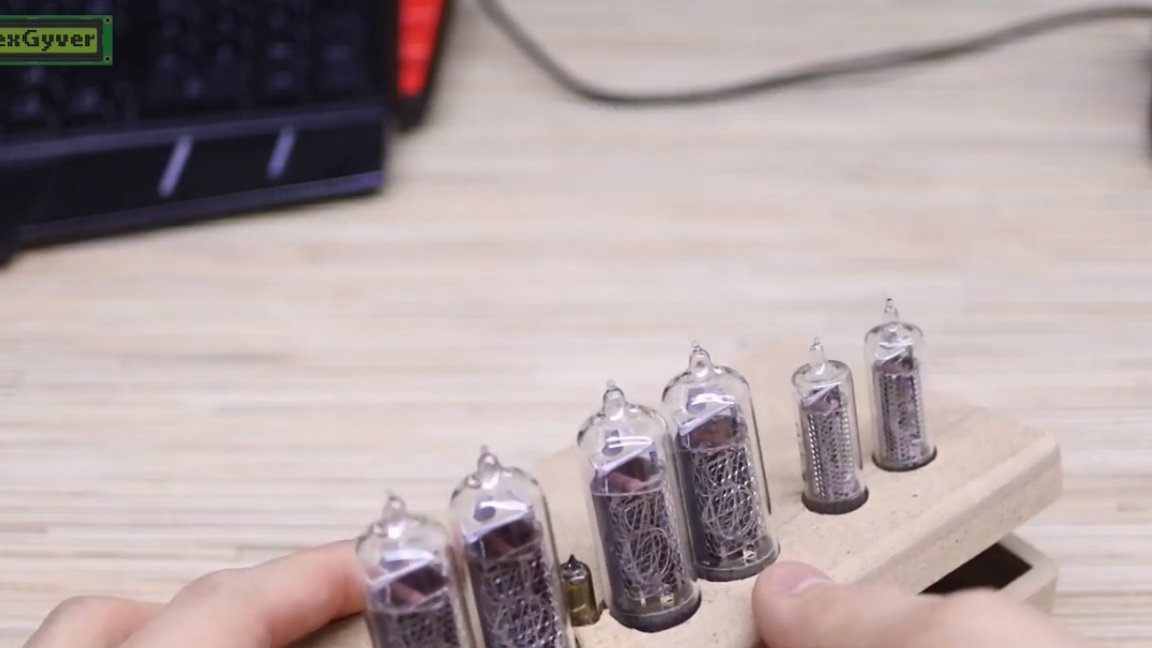
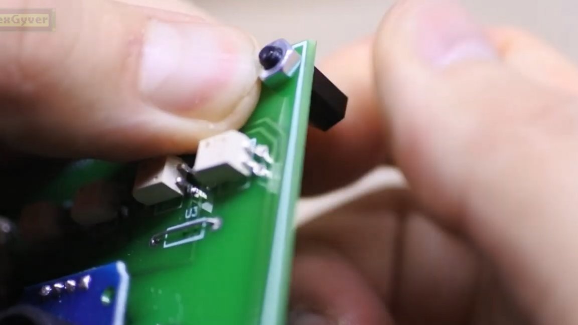
Excellent. We carefully watch how to solder indicators. On all indicators, one leg is marked white - this is the anode.
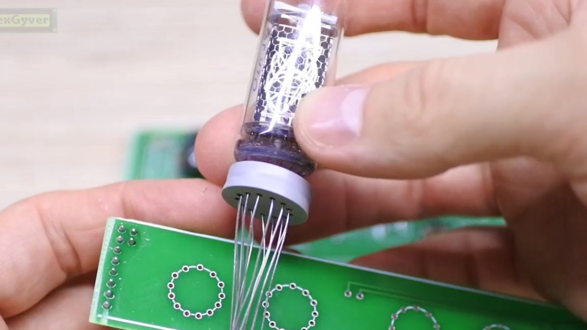
The lamp must be inserted so that the anode leg hits this hole, these are the anode roads.
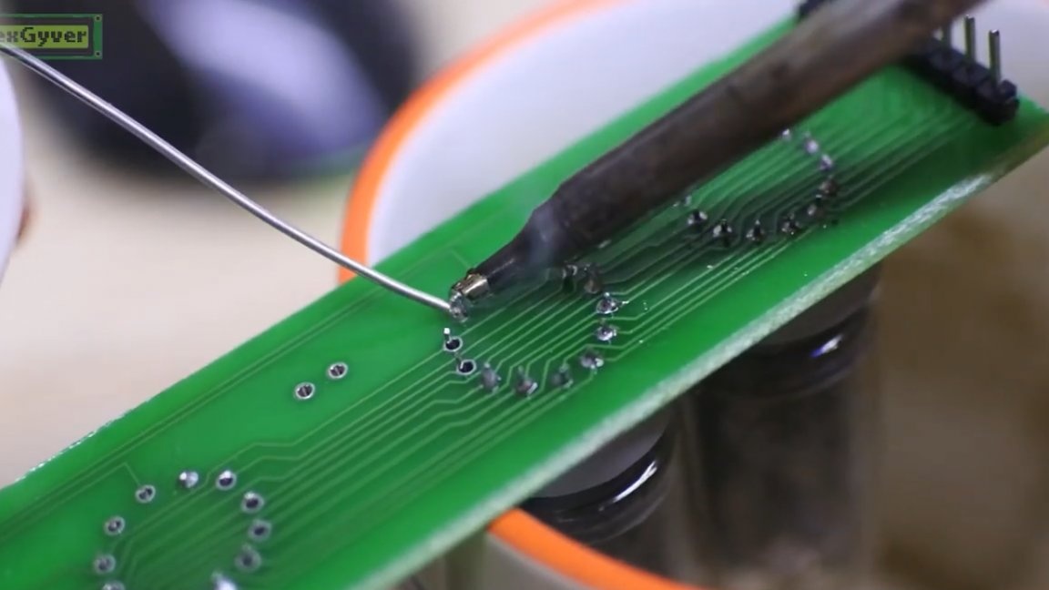
After soldering, be sure to wash the flux, otherwise several digits may burn instead of one. Next, unsolder the remaining sensors and tweeters, if necessary, and solder the wires to connect the buttons.
The temperature sensor had to be carried out on wires to place it far from sources of heating.

We take out all the buttons and the alarm switch on the wires. We will also make a clock module on wires.
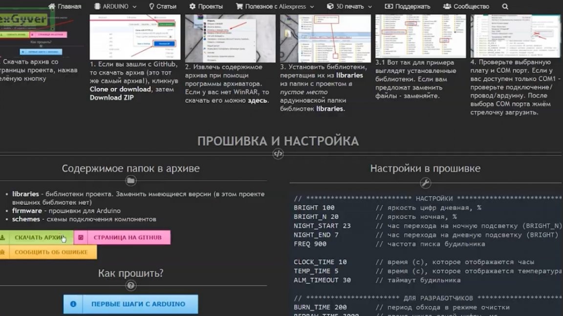
With download the archive, in which there is firmware and libraries. Download the firmware.
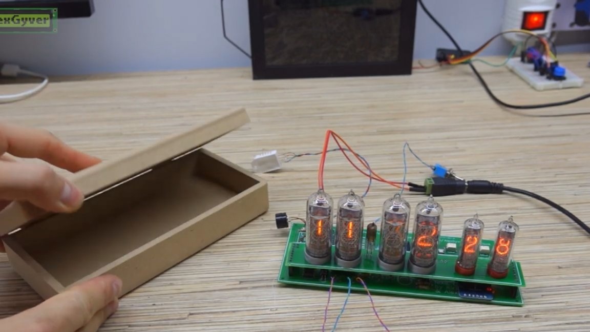
We check.
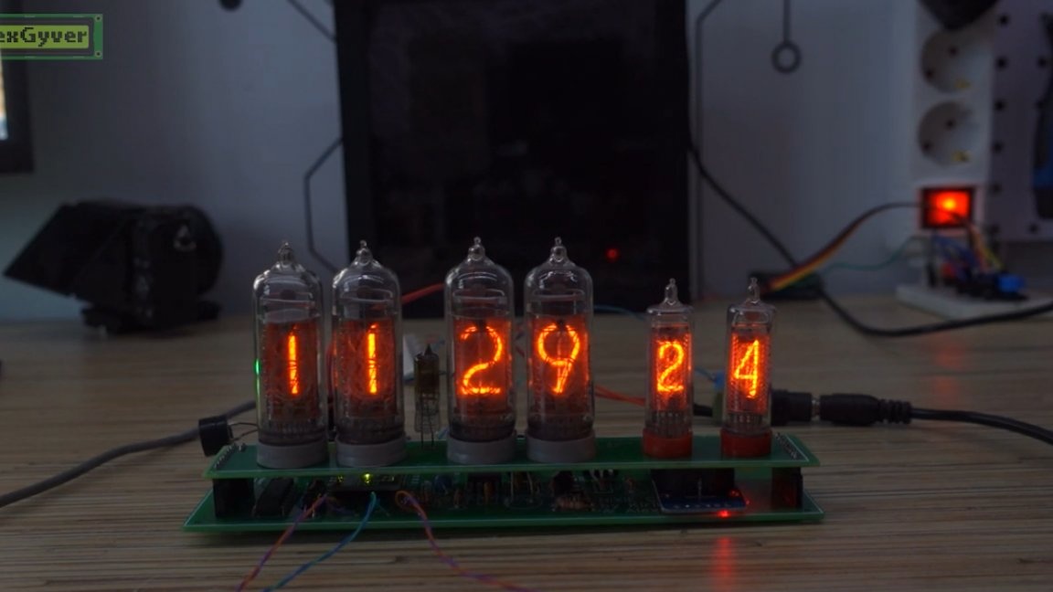
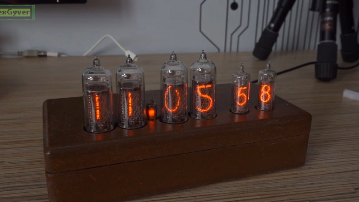
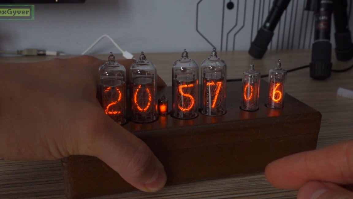
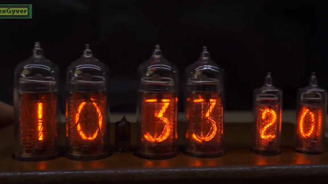
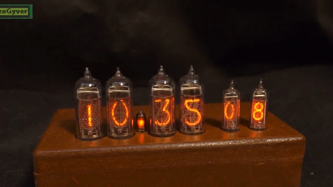
Everything works! Congratulations, we made a tube clock.
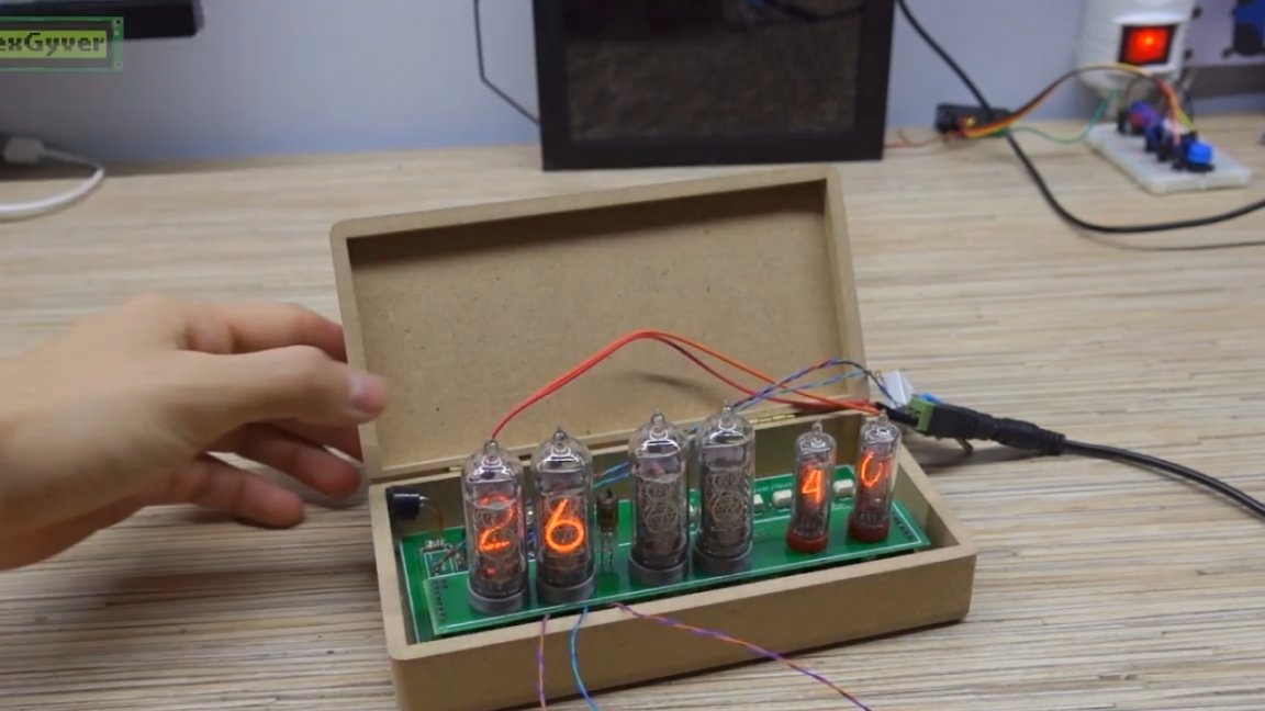
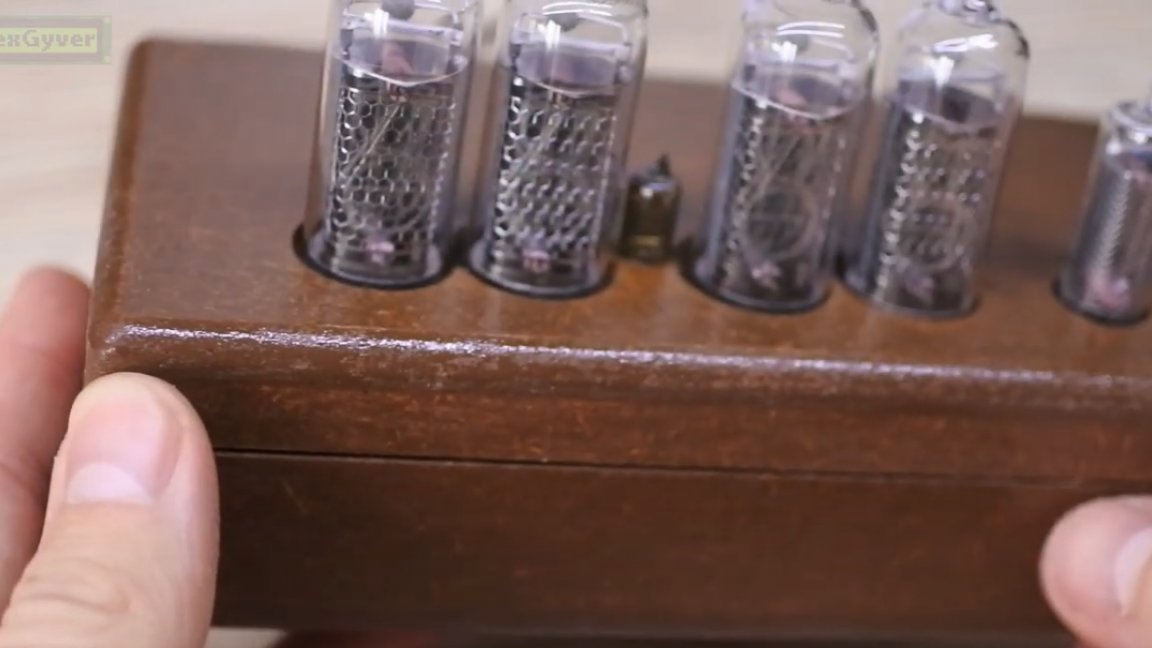
Now for the case. For a long time, the author was looking for the most affordable and wooden option, and yet he found just such a blank for a makeshift box that is ideally suited to fit the board.
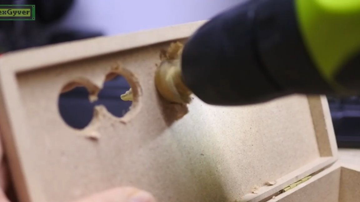
We also make holes for tweeters, wires, buttons and switches.
The board needs to be raised, the author uses the usual racks for printed circuit boards.
The author painted the case under a nut. Not very successful, better use a stain.
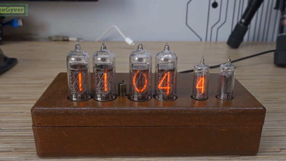
Done! It remains to show how to use all this. Before flashing, you can configure some points: clock mode times and temperature and humidity display modes. The author set 10 seconds on the clock and 5 on the temperature. Temperature, by the way, on the left, humidity on the right.
There are 2 modes of brightness indicators, day and night. Accordingly, for this setting.
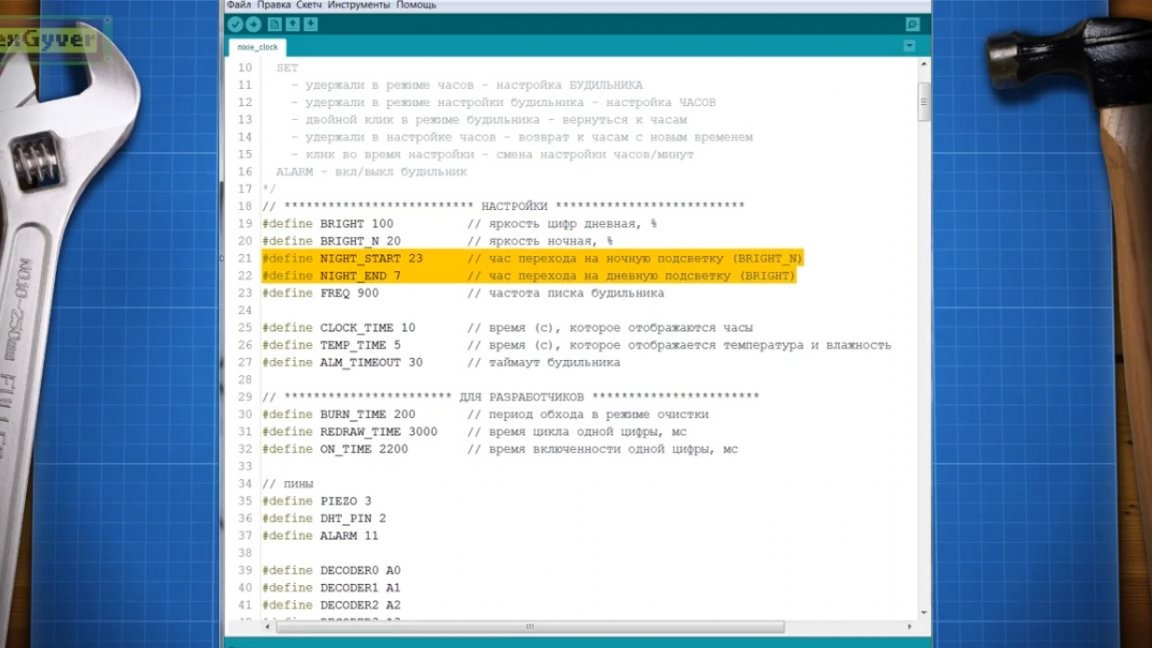
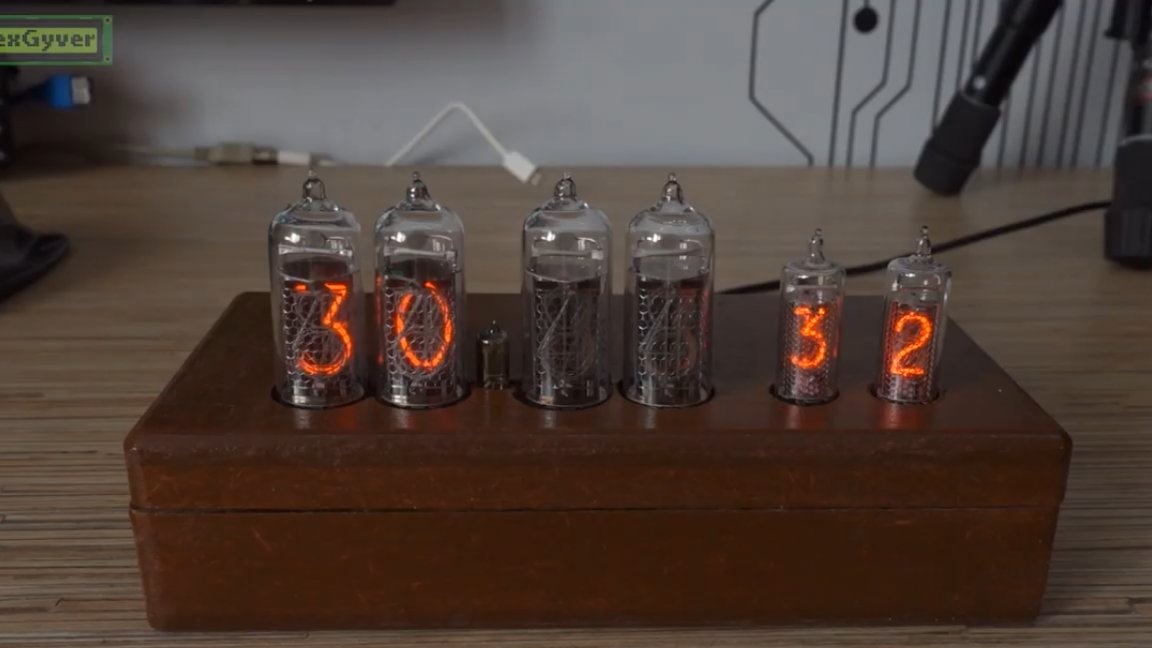
Well, the time after which the alarm itself will turn off after the alarm starts.In general, the watch is ticking, and every minute they get the so-called anti-poisoning of indicators. All numbers are quickly sorted so that rarely included numbers are not buggy and turn on immediately. In general, we have 3 buttons: selection, and increase / decrease. When you click on the "select" button in temperature mode, you will immediately switch to clock mode.
Holding the “selection” button, we get into the alarm setting mode. Use the up / down buttons to change the number. By clicking on the “selection” button, you can change “clock settings” and “minutes settings”. The keyboard is resistive.
Holding the button again, we get into the time setting mode. Set up, hold again and get back to just a clock mode. You can also exit the alarm time setting immediately by double-clicking on the selection button. That is, exit bypassing the time setting.
Yes, the wake-up call is disgusting, but it wakes you up best. You can verify this by looking at the original author video:
We have everything with this watch today. Thank you for attention. See you soon!