
In this article, John, the author of YouTube channel "John Heisz - I Build It", will tell you how to improve the guide mechanism of the band saw.
Materials
- Maple board
- Steel round timber
- Graphite sticks
- Bearing
- Two-component epoxy resin
- Wood screws, washers, nuts
- Wing nuts.
Instruments, used by the author.
- Band-saw
- A circular saw
- Screwdriver
- Bulgarian
- clamps
- Belt sander
- Vise, file, screwdriver.
Manufacturing process.
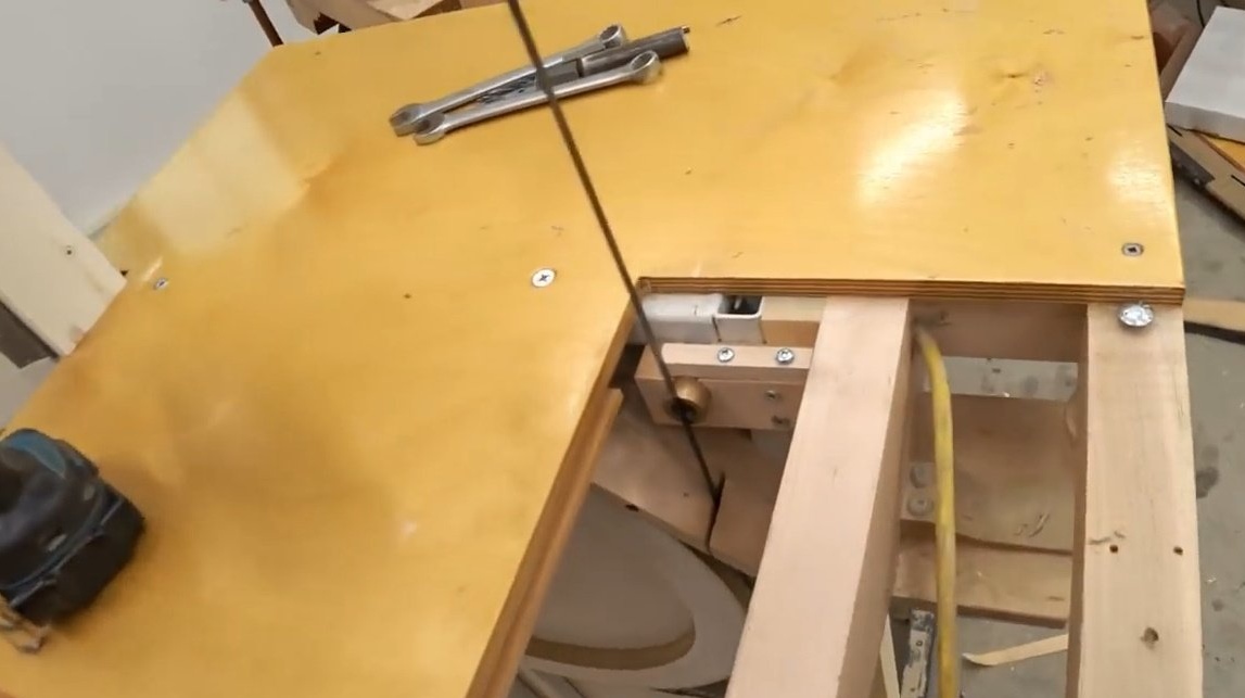
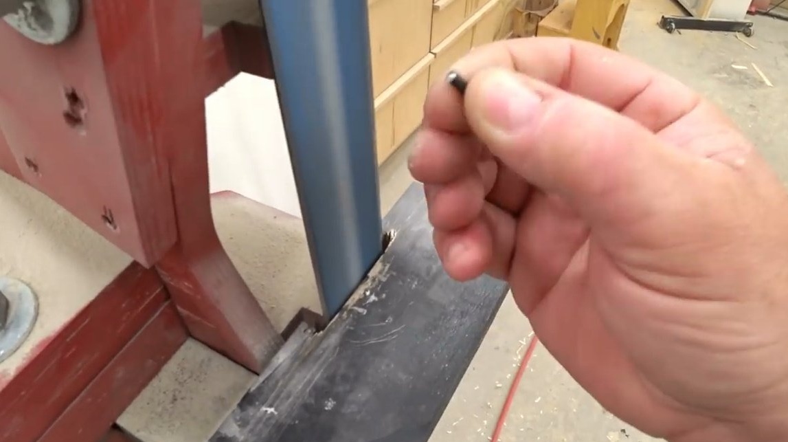
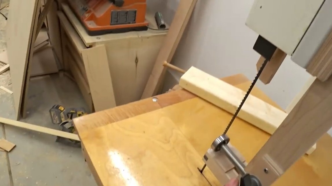
Here is the old system that guides the movement of the band saw blade. And although she performs her functions, John is not satisfied with her work.
This circumstance pushes him to the general revision of the system. John changes the upper wheel shaft. There is a separate video about this, and those interested can follow this the link.
In this article, the author intends to tell you how he managed to create a new guide for the saw blade. John begins the restoration by replacing the lower rail, and it, in fact, is the main one.
Here is a bronze plain bearing, which basically serves as a thrust bearing.
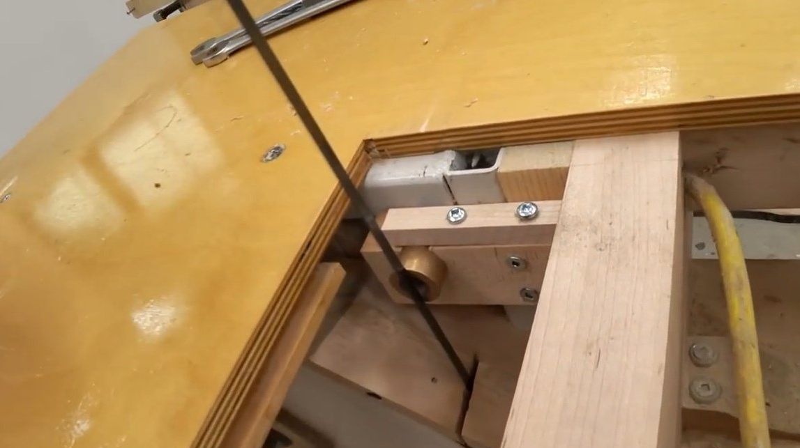
The author has not yet touched the side guides, but begins precisely with a thrust bearing. When it comes to the top rail, John will use a regular ball bearing.
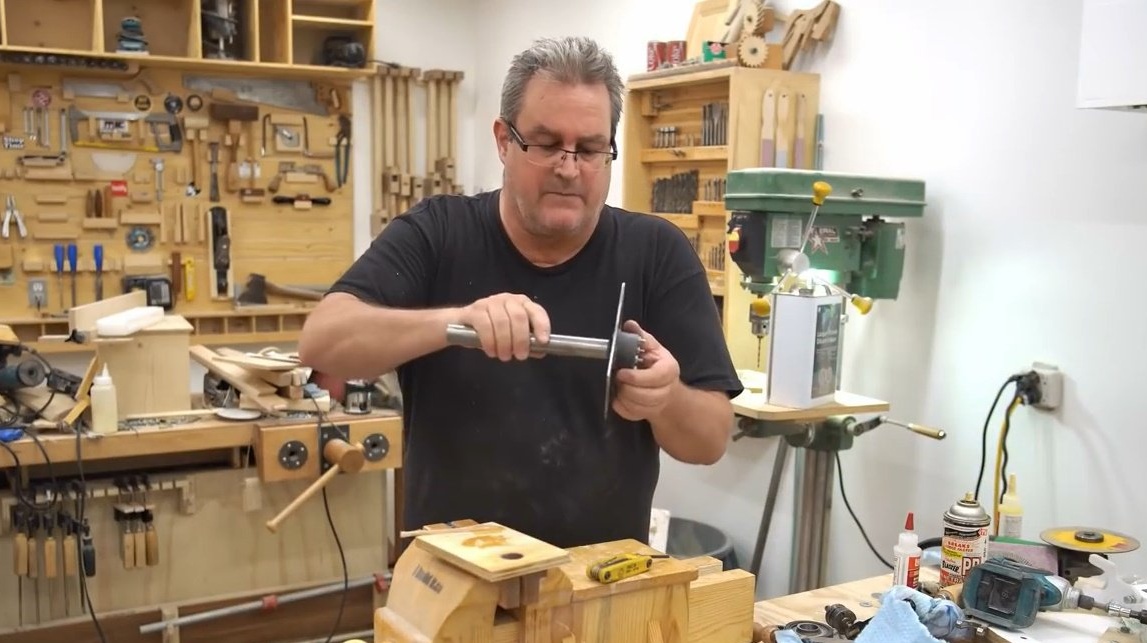
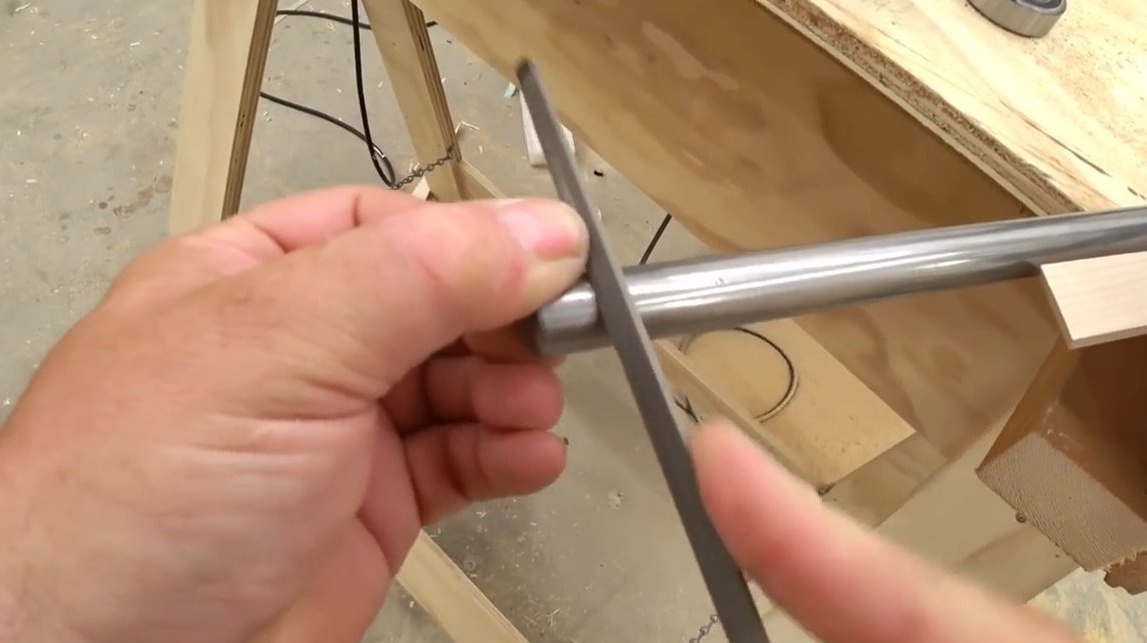
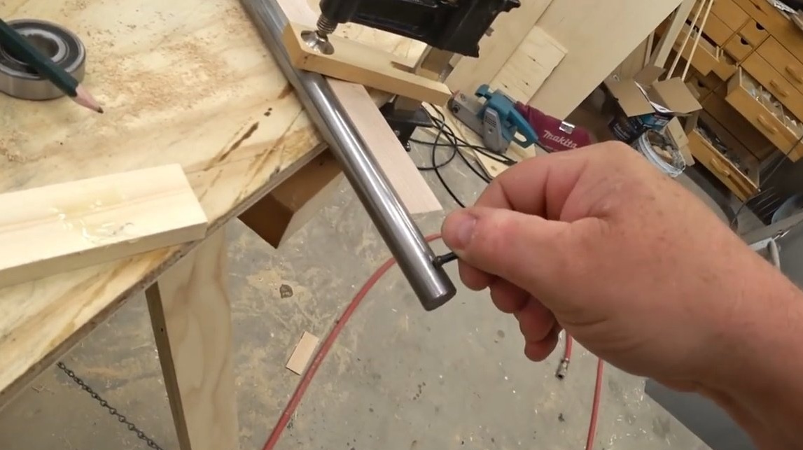
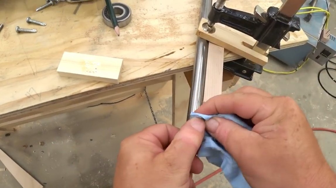
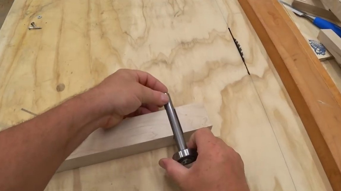
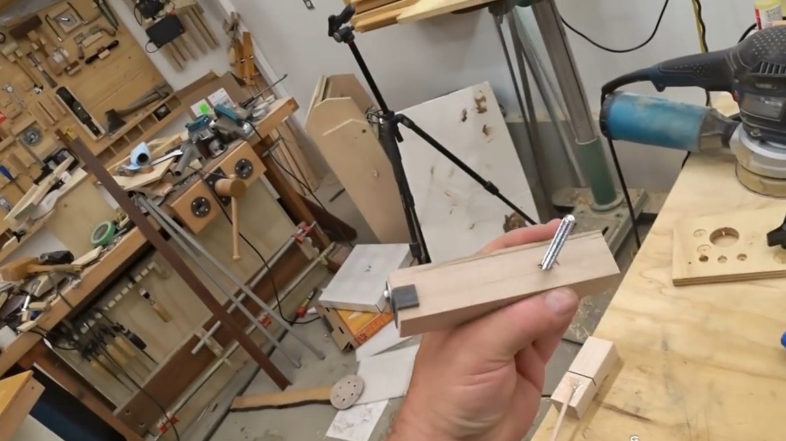
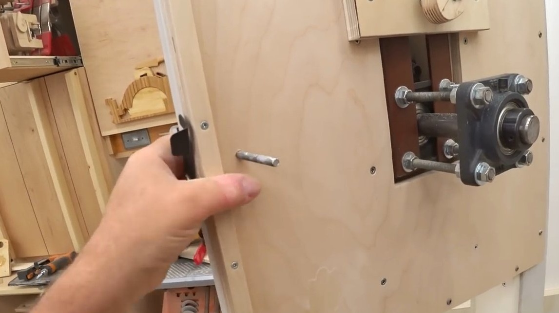
He mounts it on a 5/8 inch shaft with the expectation that the shaft will move forward and backward, thereby allowing it to adapt to the changing dimensions of the workpieces. As a material for the shaft, the author chose a steel round log, and marking it, makes a file with a file.
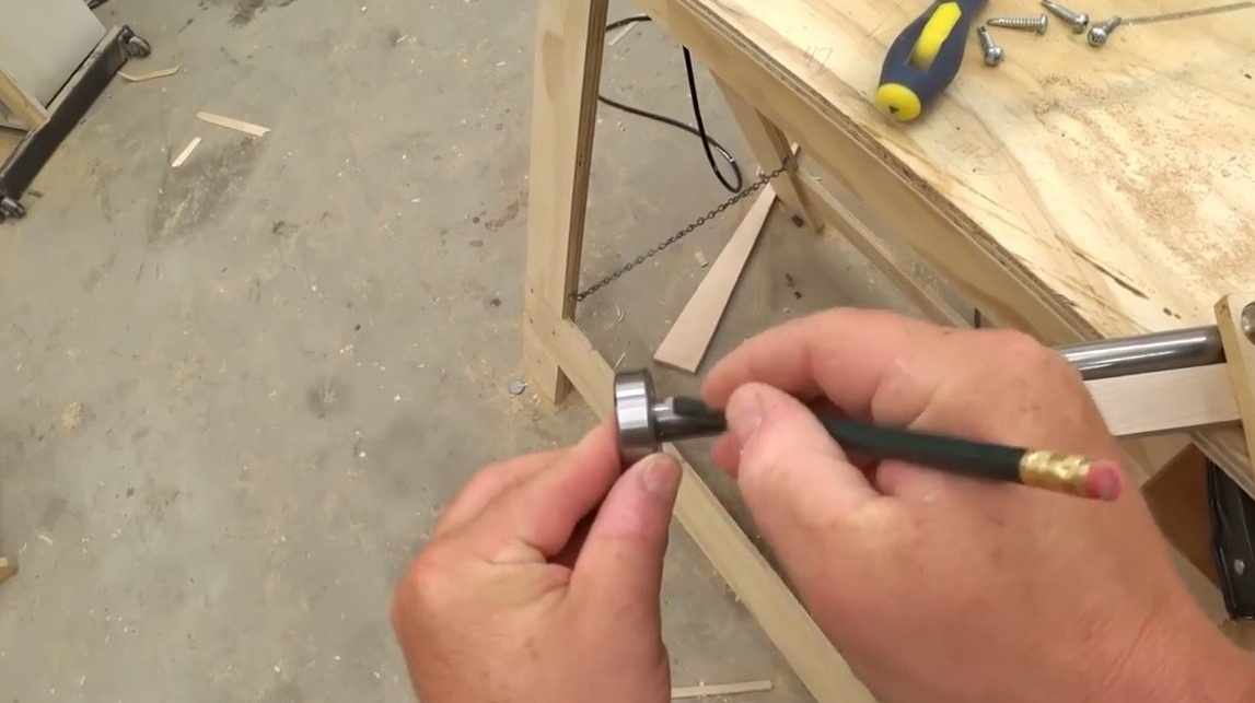
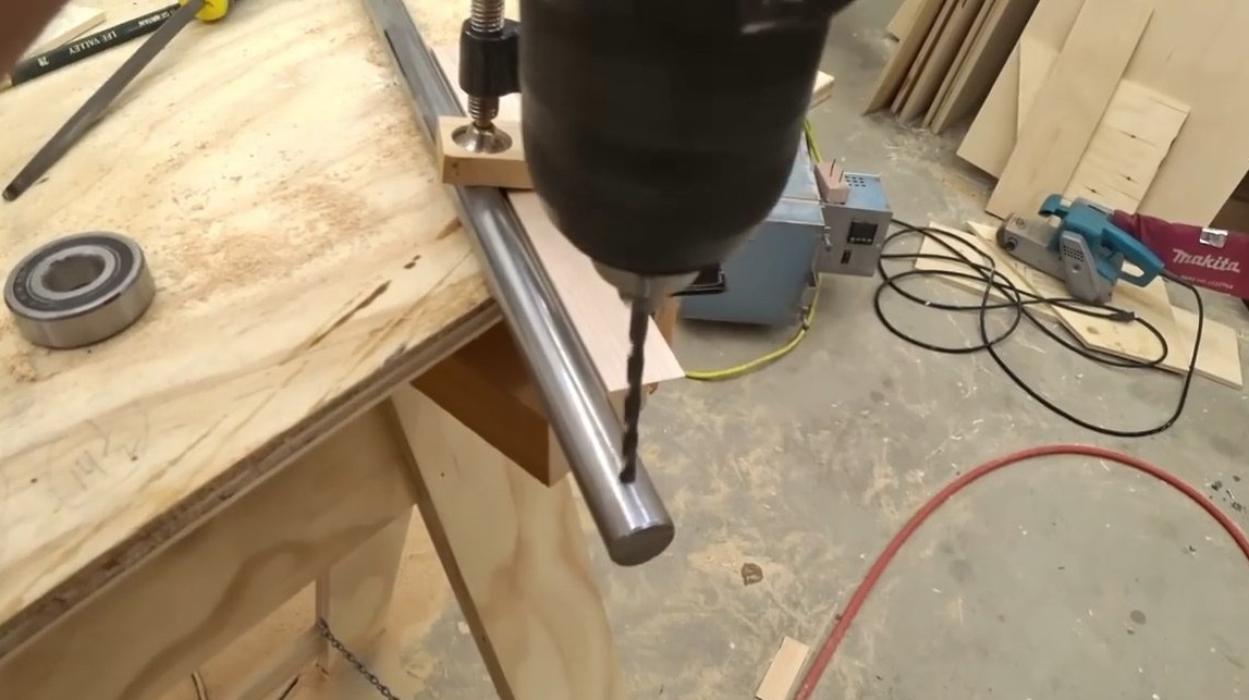
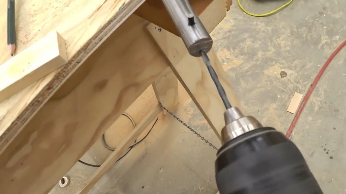
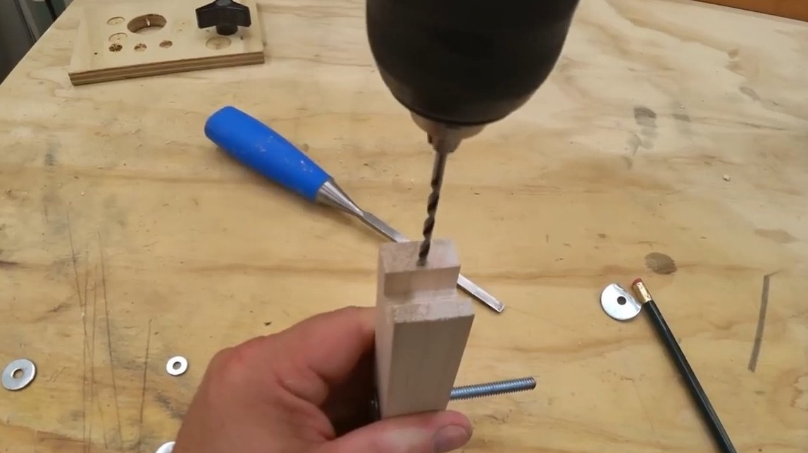
Then he drills a dowel hole in the round timber.
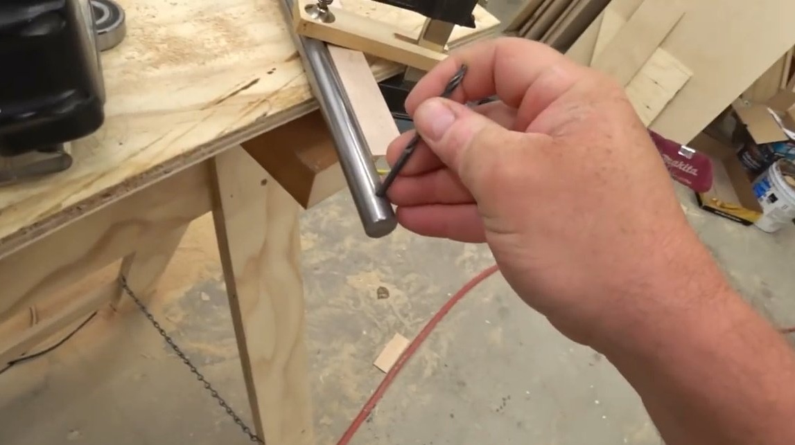
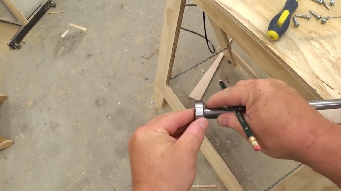
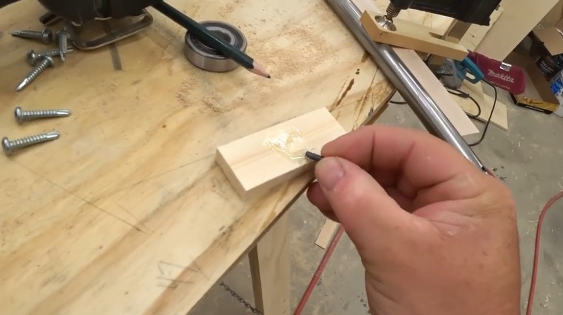
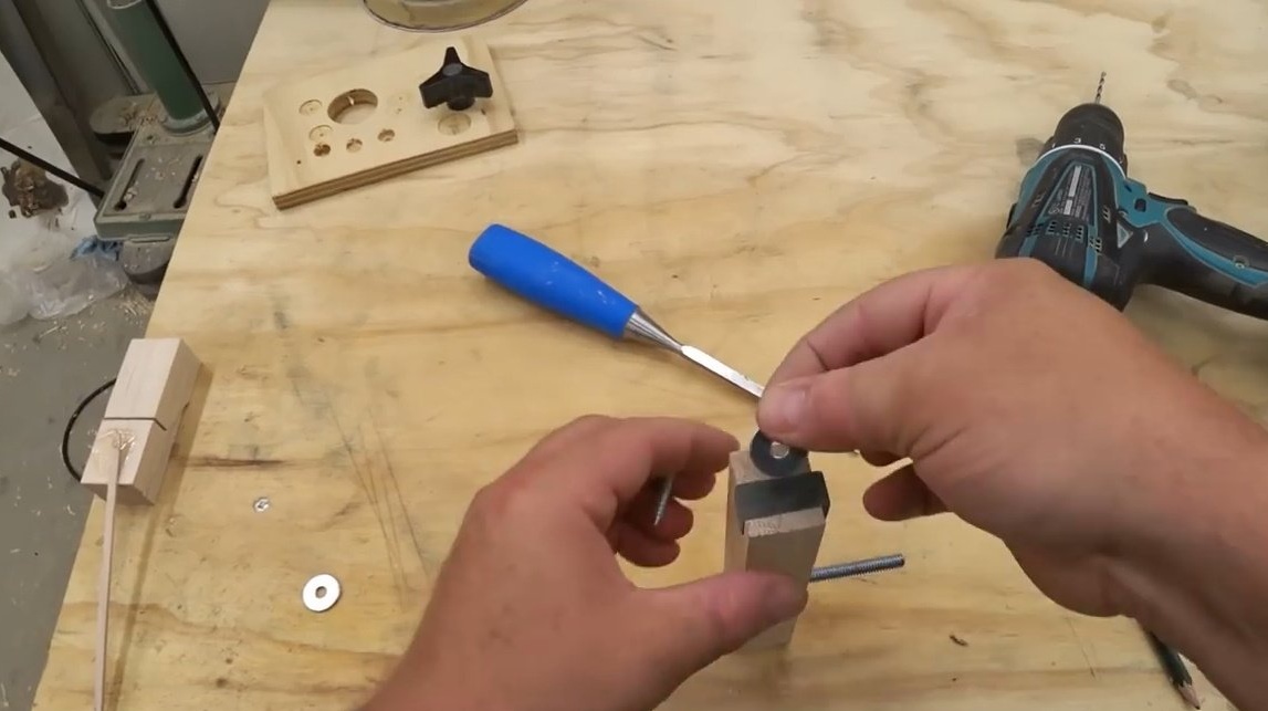
The author knows from his own experience that thrust bearings wear out pretty quickly and must be replaced. Given this circumstance, it is inappropriate to use the mount "for centuries." The master is going to slightly cut the shank of the drill and paste it into the hole he made.
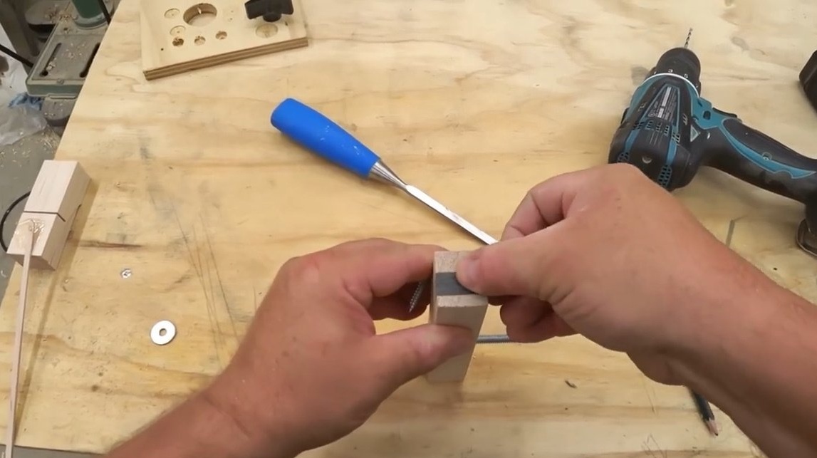
He mixes a little resin on a wooden block, and dips the resulting dowel into it. Such a cunning design will create a kind of limiter for the bearing and prevent it from slipping.
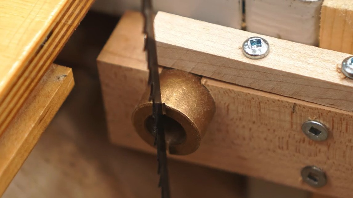
After the resin hardens, it installs the bearing in place.

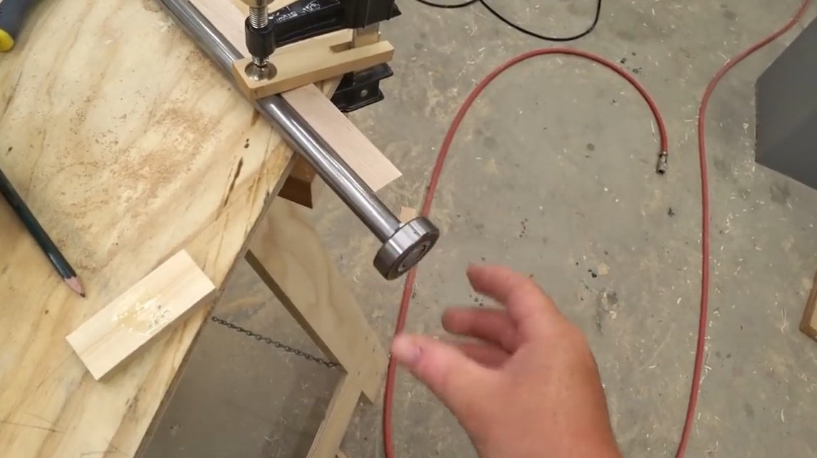
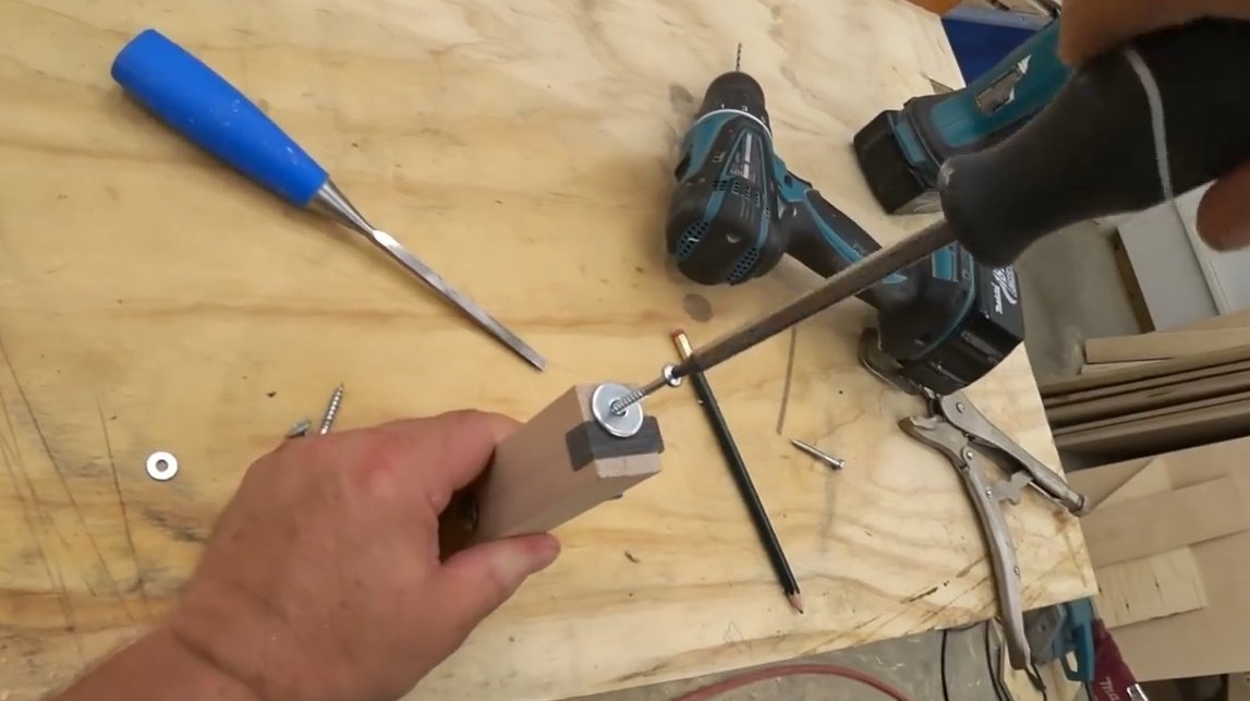
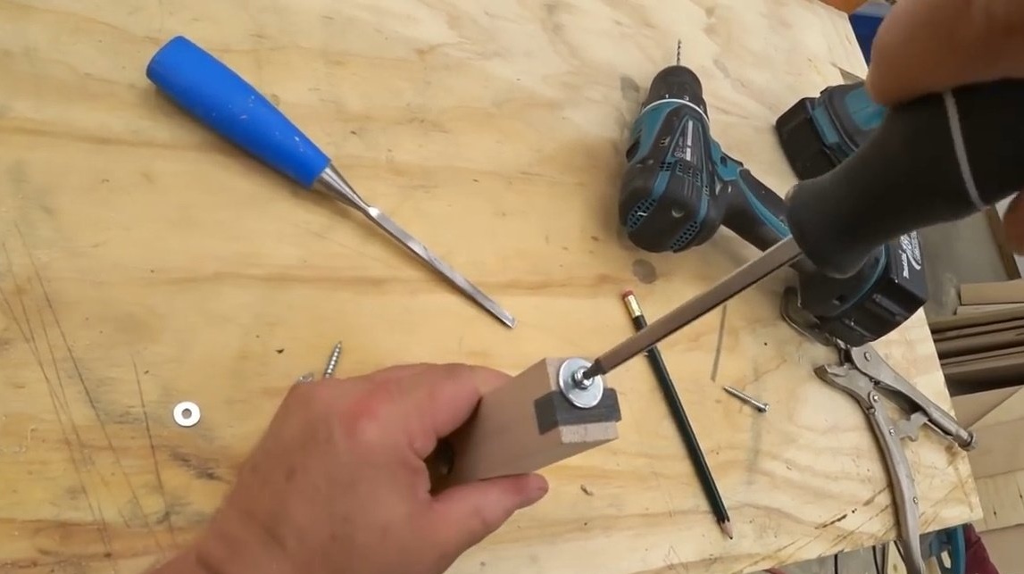
Now, in order to keep the bearing from forcing forward, John drills a hole in the lower end of the shaft and screw in a self-tapping screw with a washer.

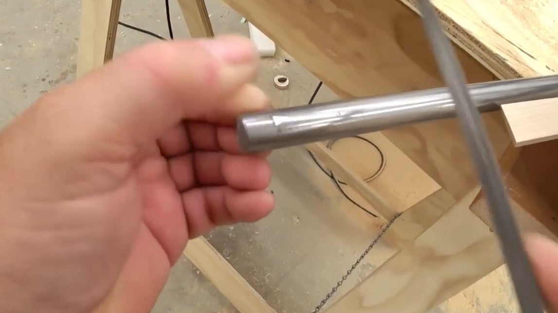
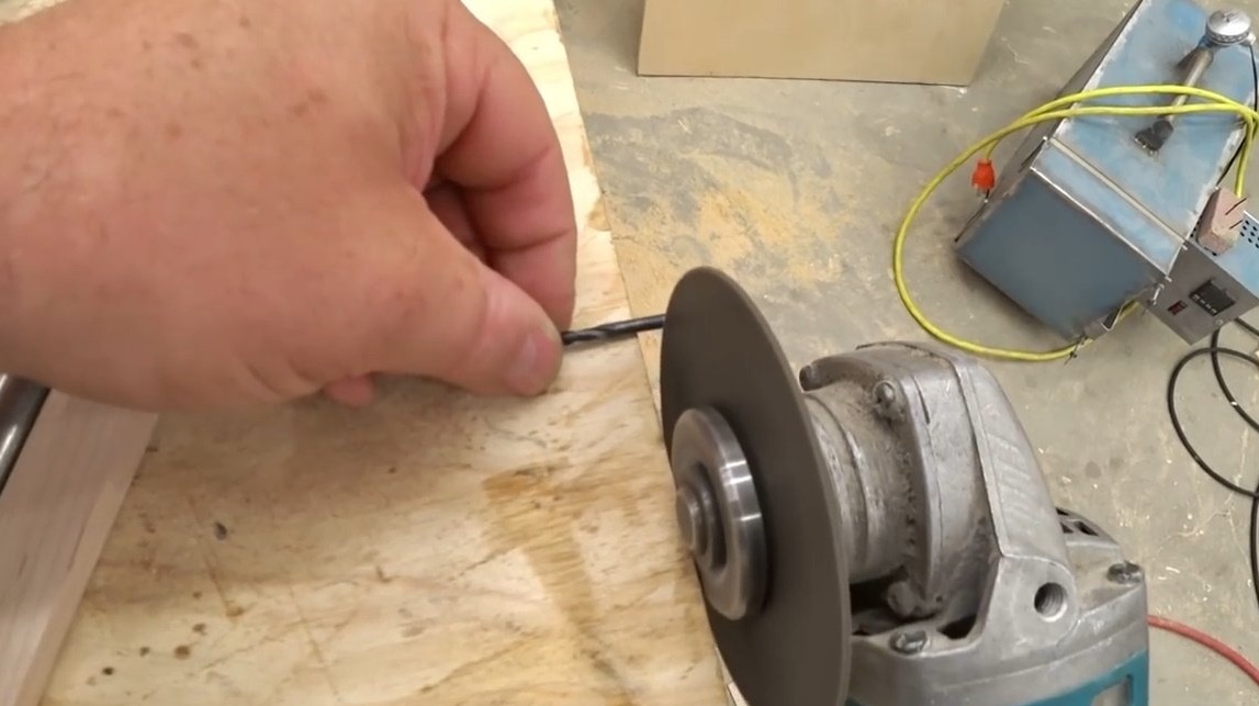
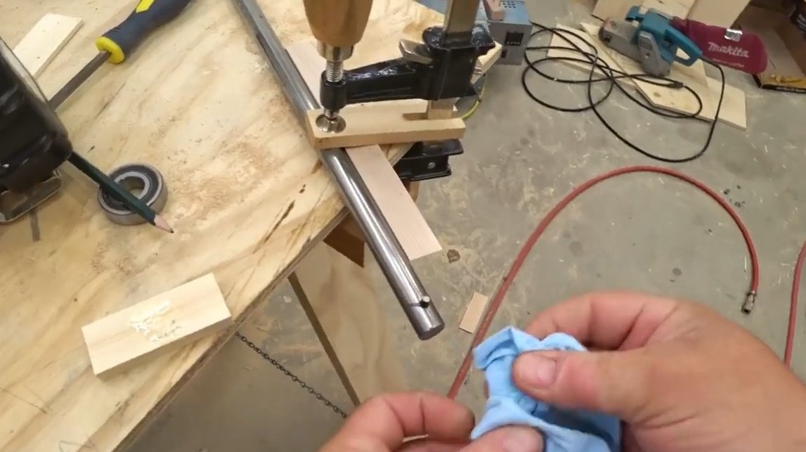
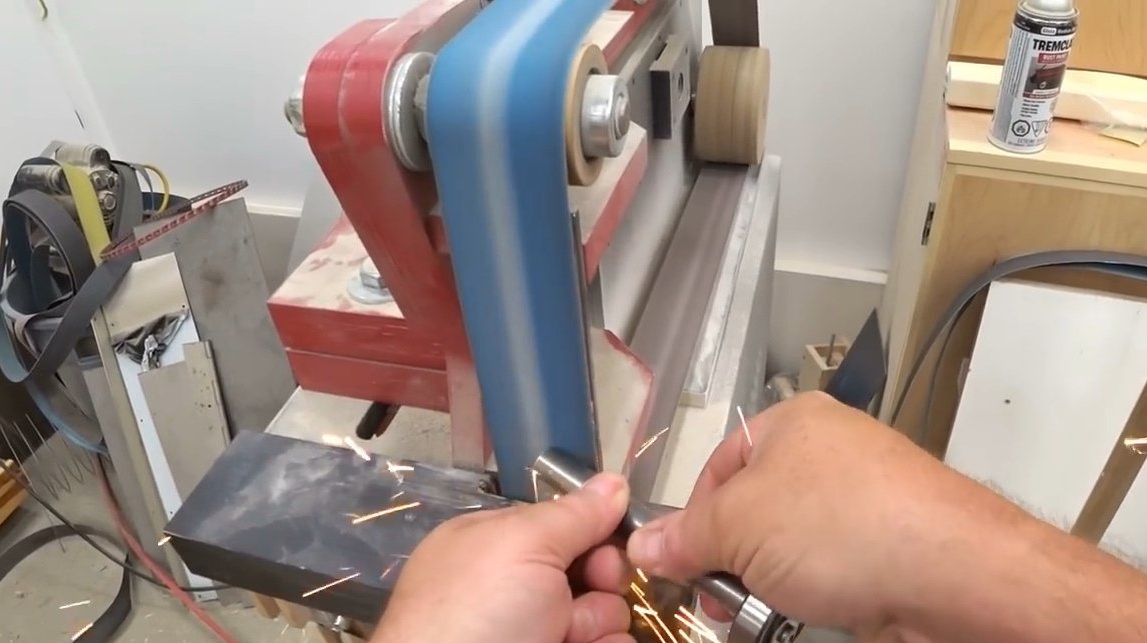
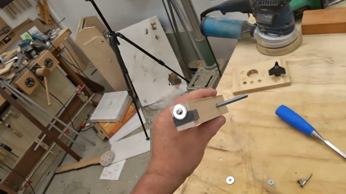
After the bearing is locked, the author can cut a 5/8 inch shaft to the desired length.
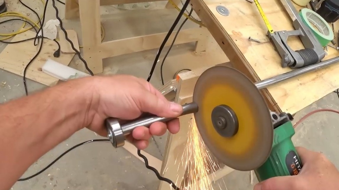
He then polishes the sharp burrs on the belt sander.
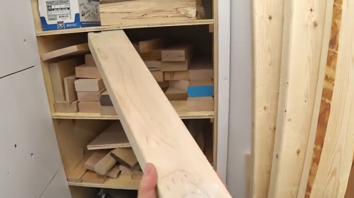
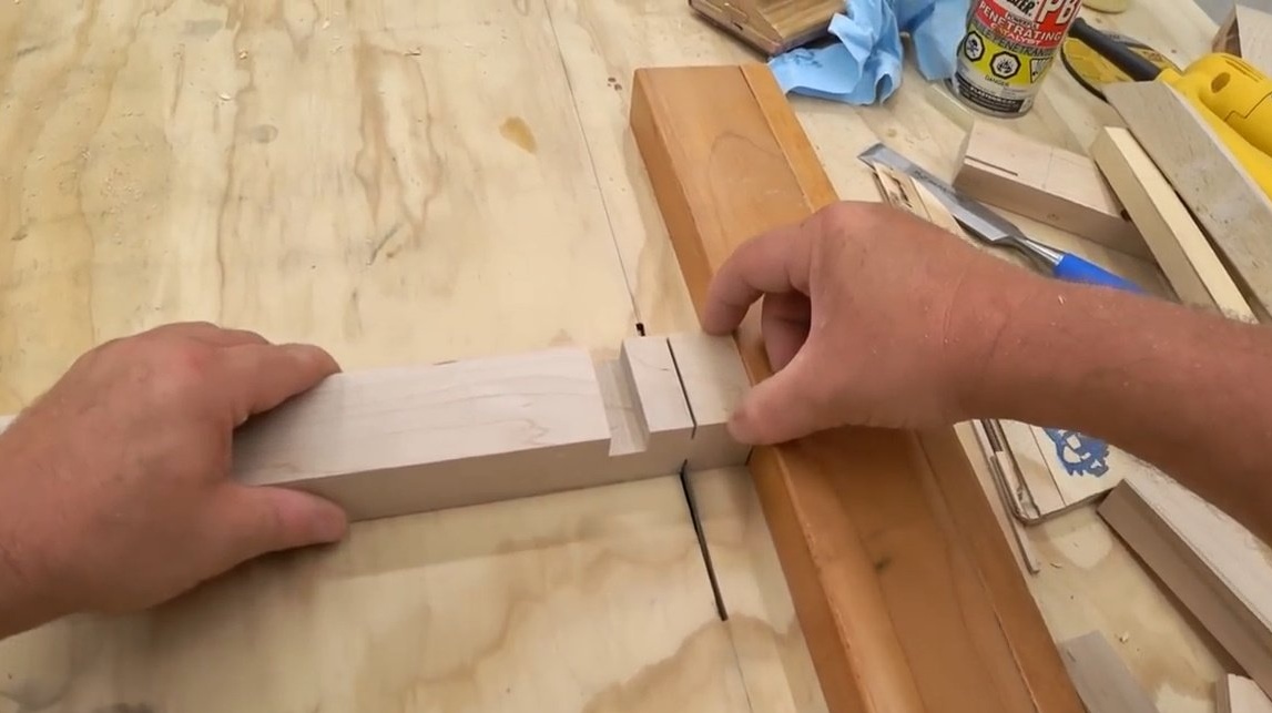
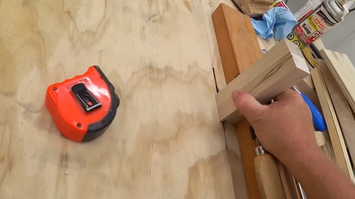
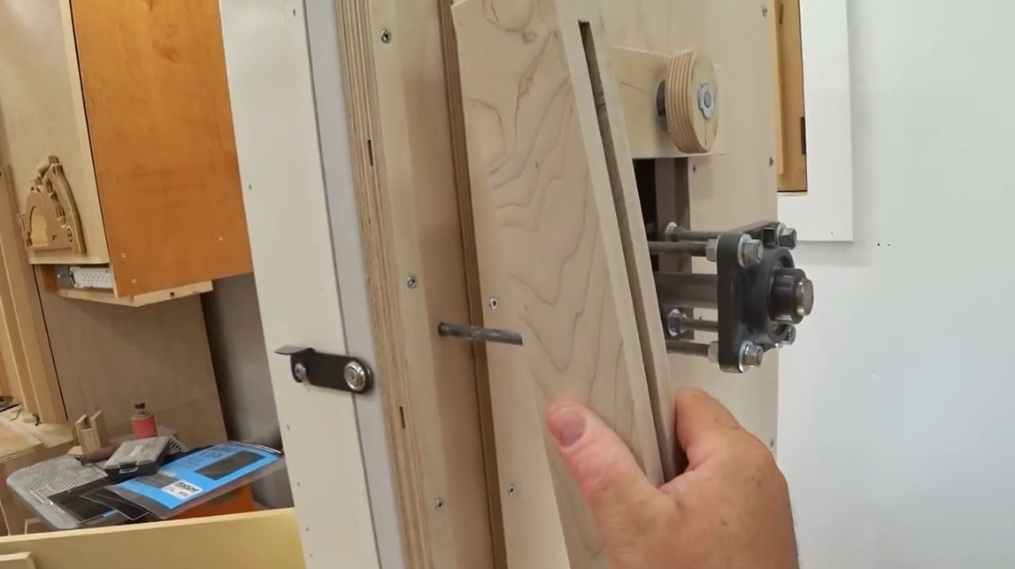
Now the author begins work on the guide rail itself. He picks up strong wood material - maple and cuts a workpiece of a suitable size.
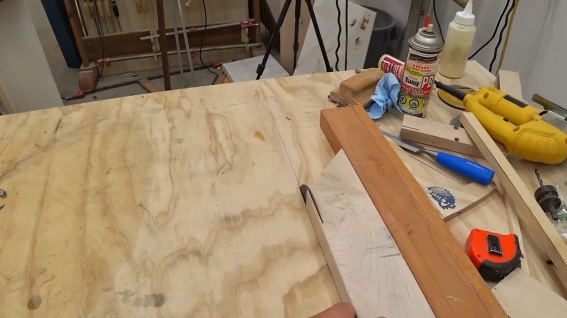
The next stage is the cutout, in which you need to fit a 5/8 inch shaft. To implement his plan, the author makes a series of grooves on the bar, cutting off a bit of material.
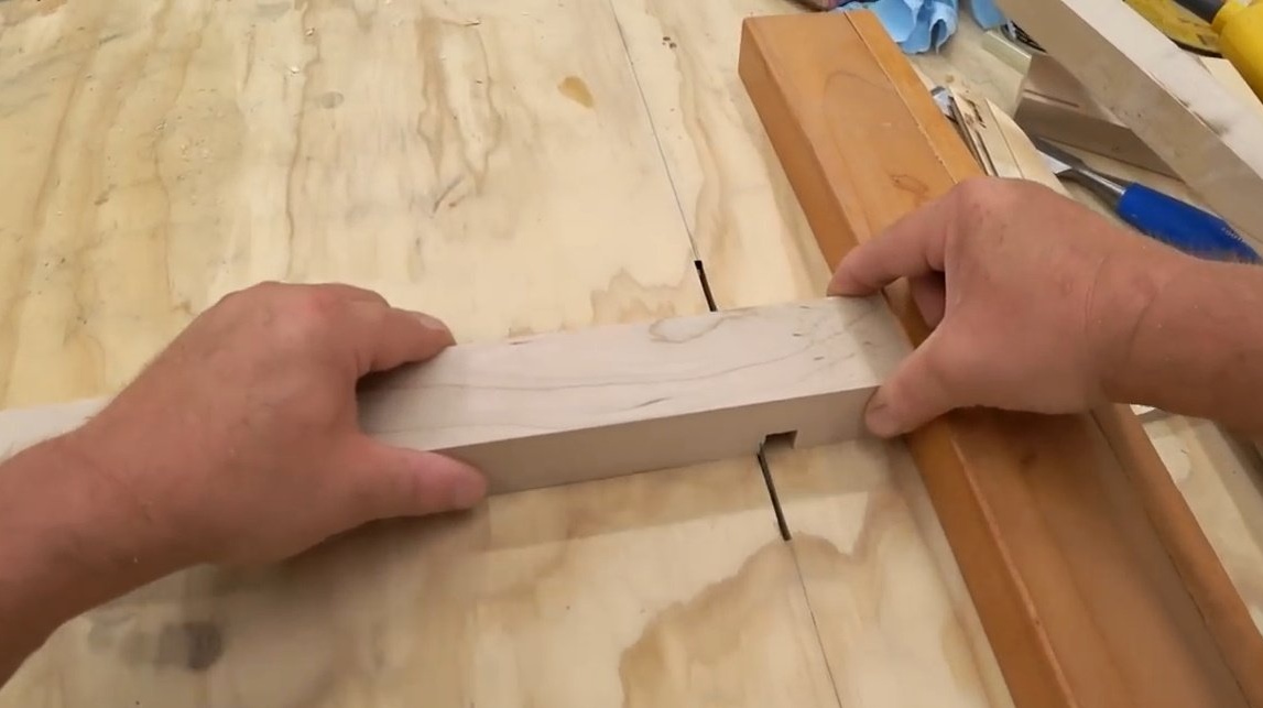
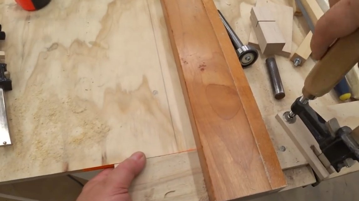
These grooves are necessary for the guide, and the author cuts additional grooves for the side stops, which will slide along them back and forth.
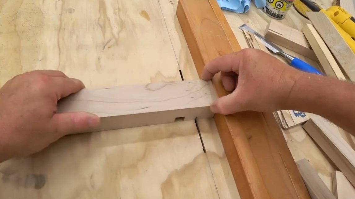
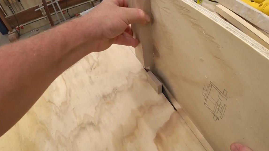
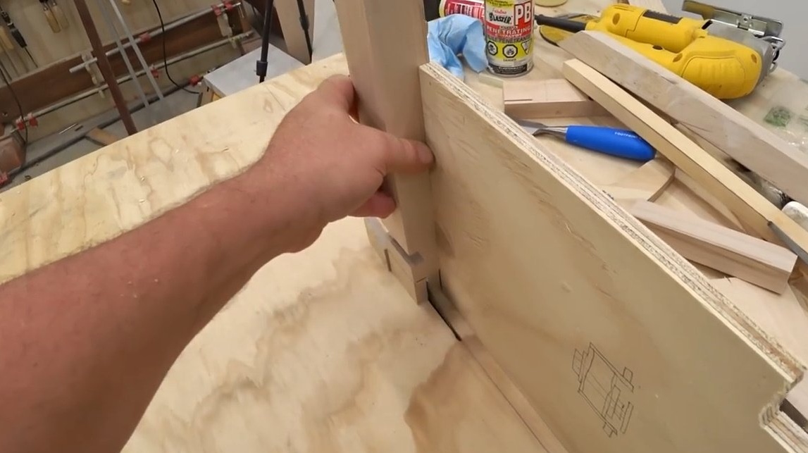
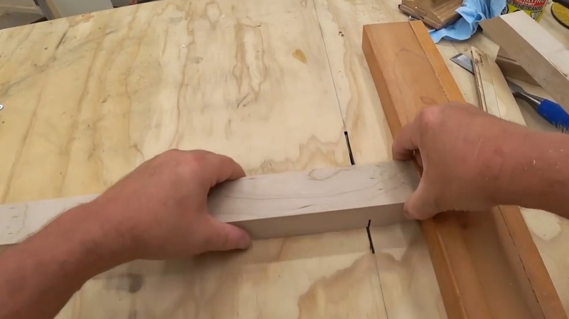
And here, to keep the workpiece in an upright position, John uses a long board as an emphasis. Side guides are also made of maple. It cuts out recesses for graphite stoppers by gradually “eating” the material until the block completely fits into the groove.
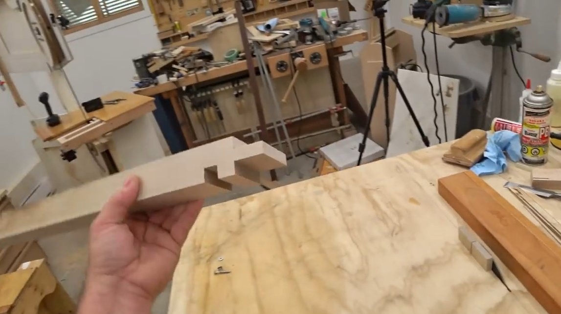
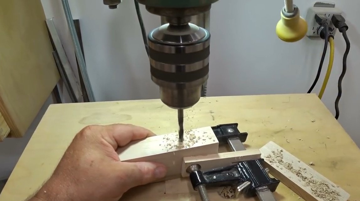
The guide also needs a slot / groove from the bottom so that the side guides can move back and forth along it and thus adapt to different blades. The author makes this groove on a drilling machine a 3/8 inch drill. He simply drills a series of holes, and then combines them.
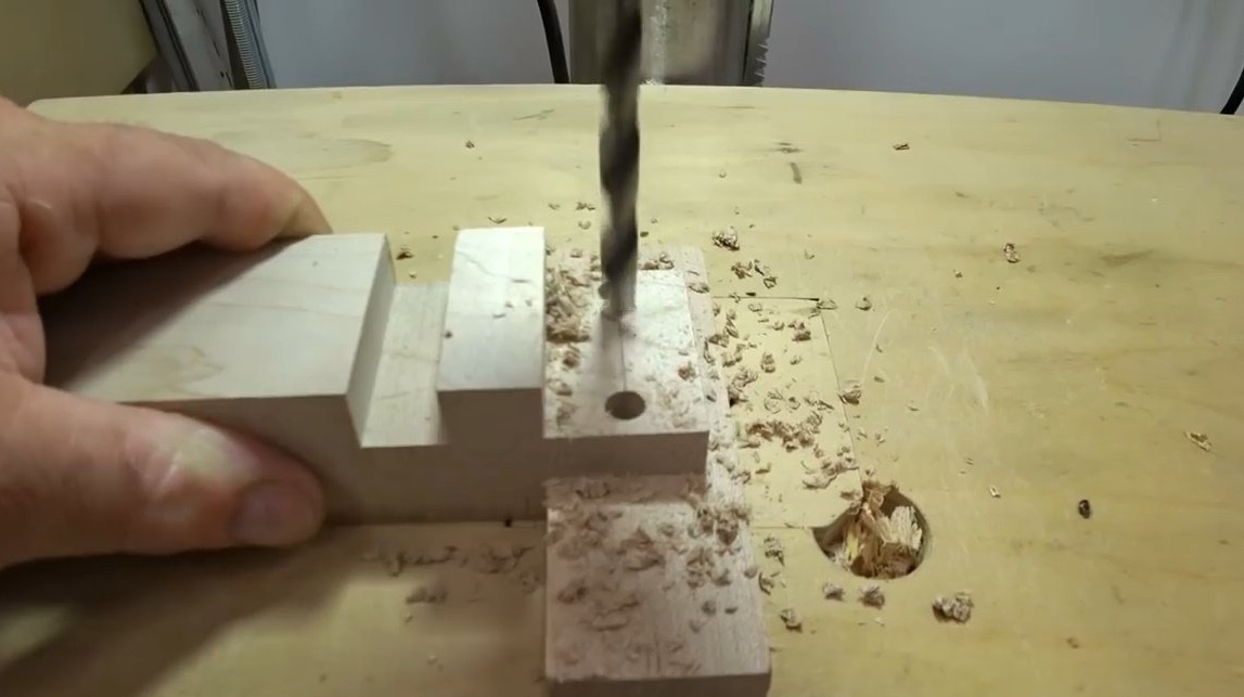
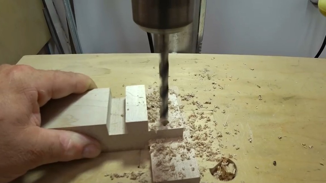
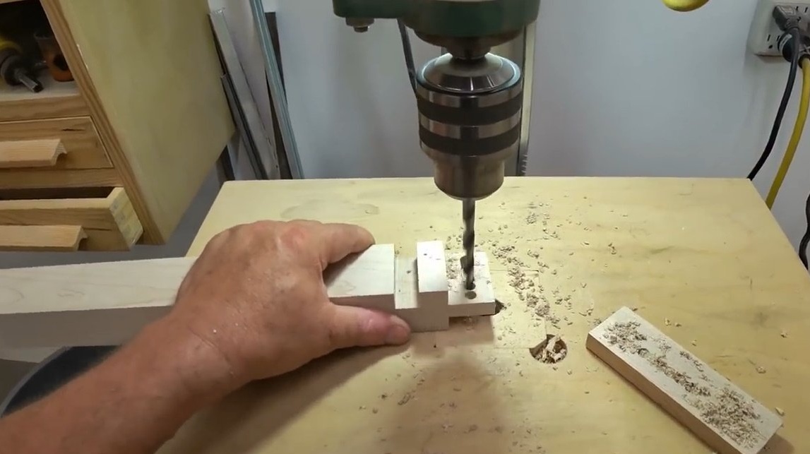
All excess is cleaned off with a file.
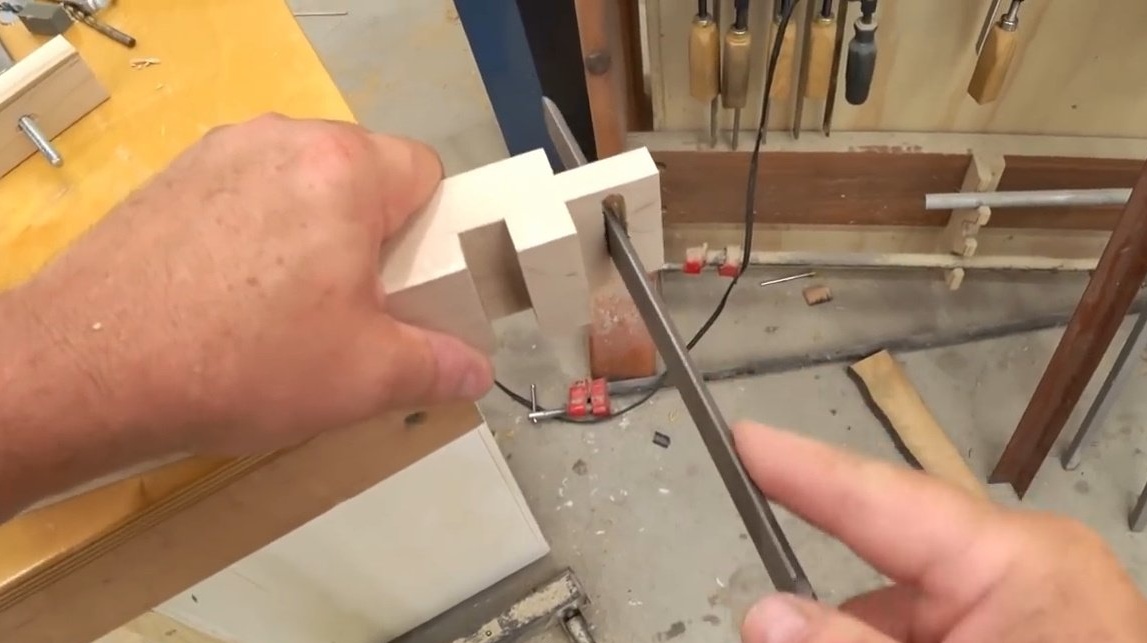
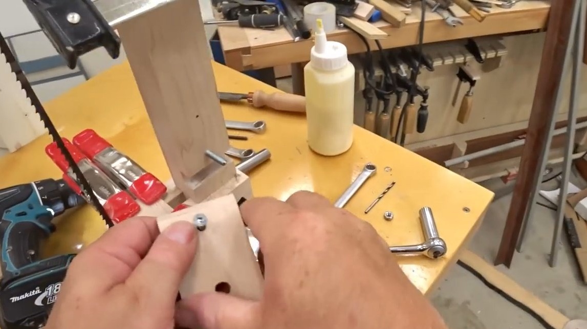
Next, you need to drill holes in each of the side guides for the anchor bolt. Another hole is necessary for the screw and washer, with which graphite guide blocks will be held.
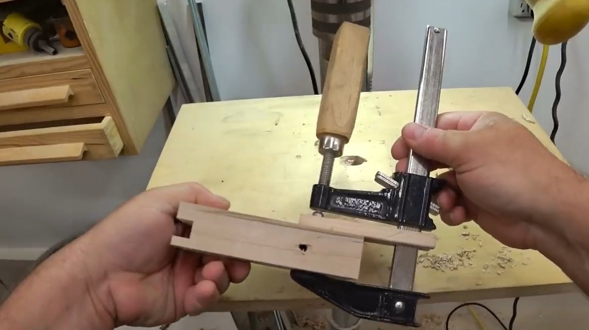
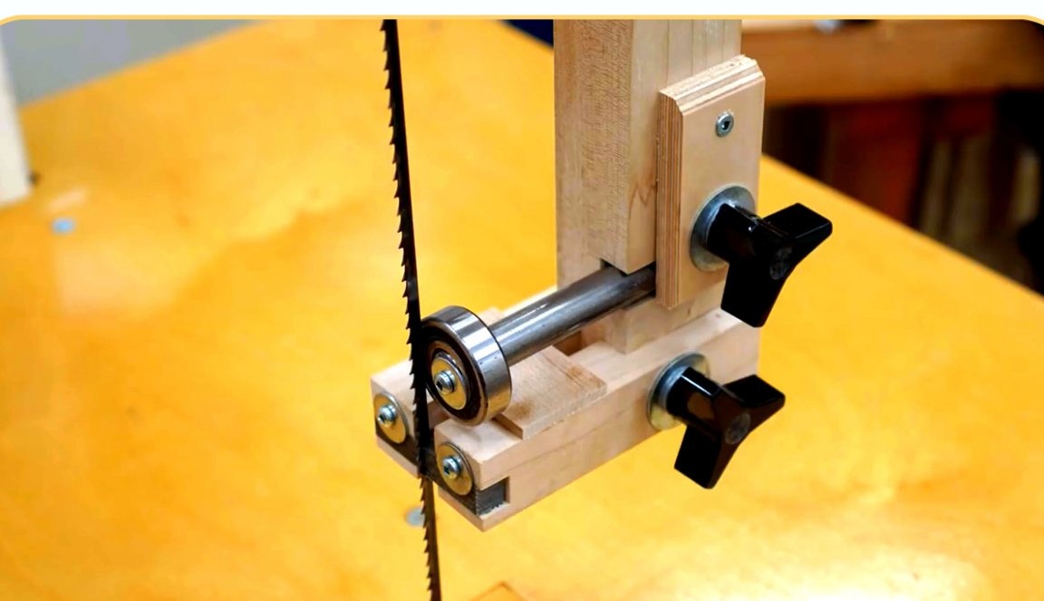
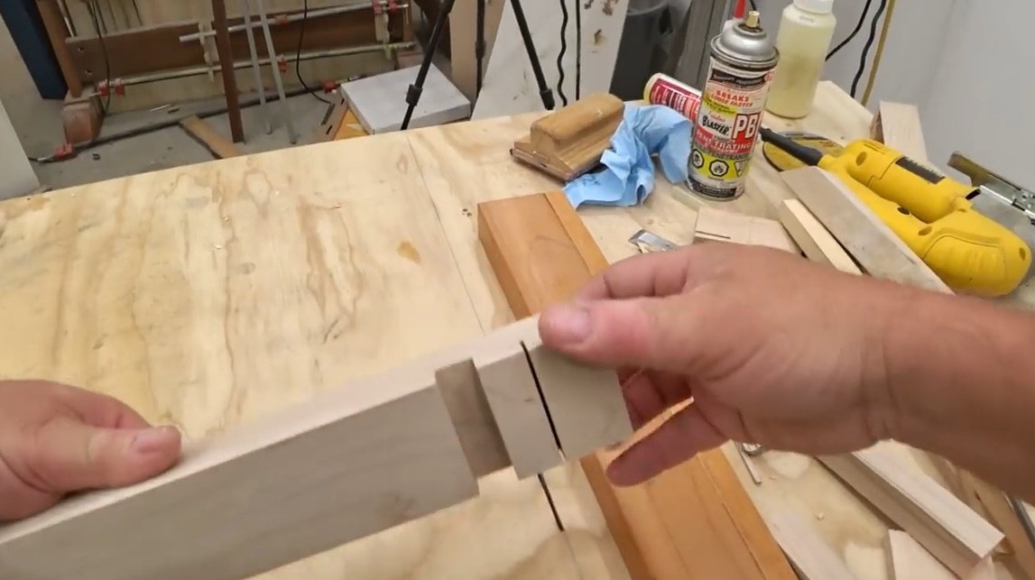
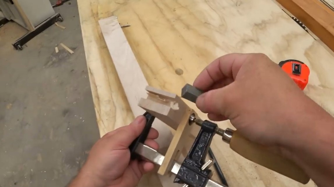
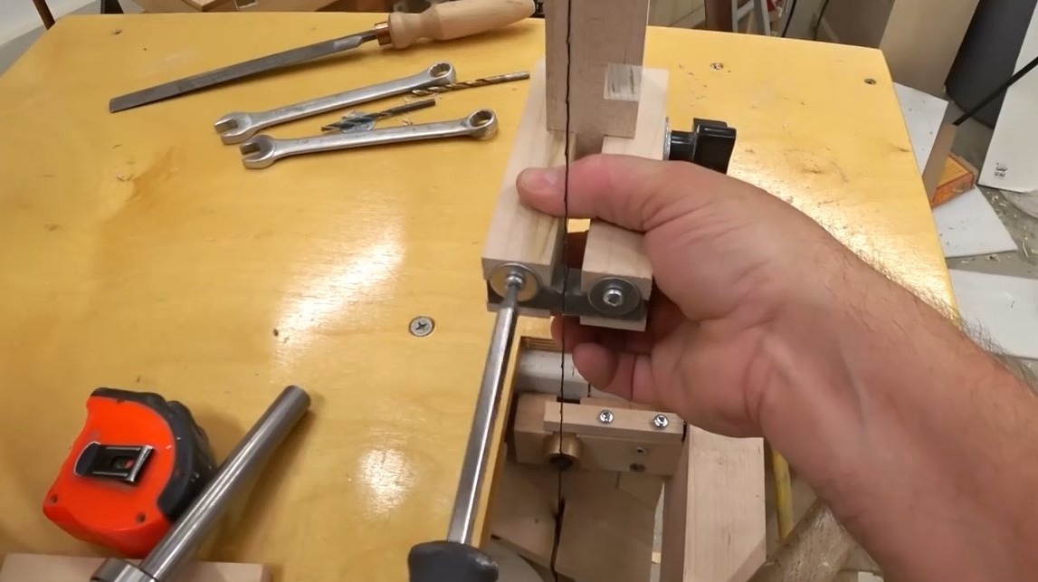
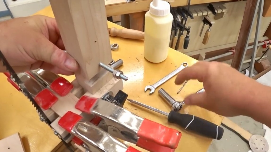
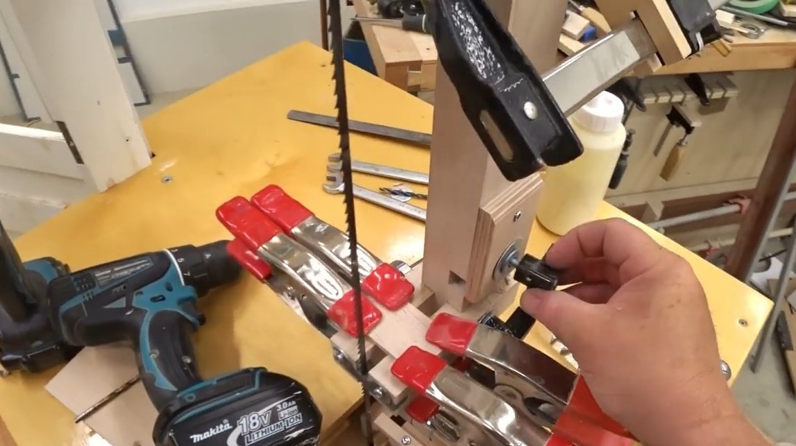
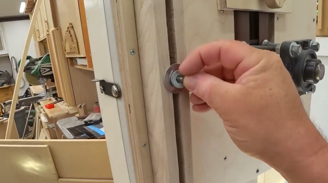
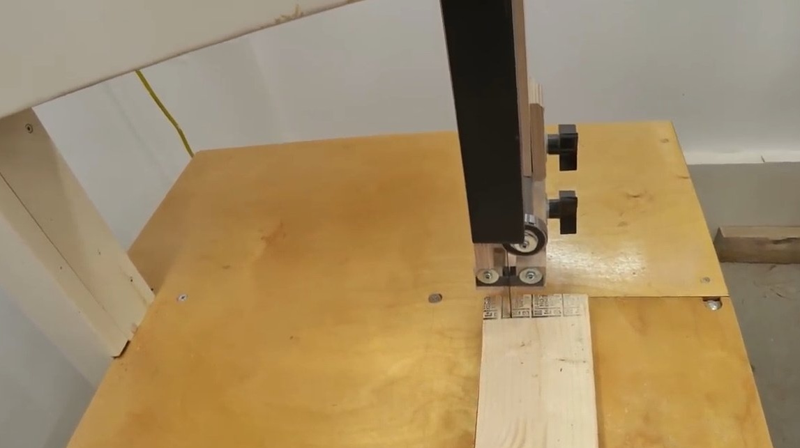
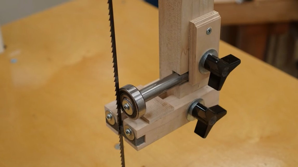
Now with the help of the guide rack, temporarily screwed into place at the saw blade, you can begin to install the side guides using a pair of washers and a wing nut.
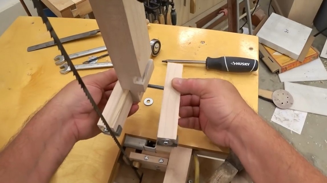
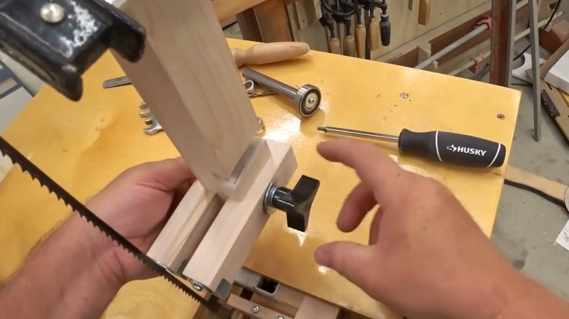
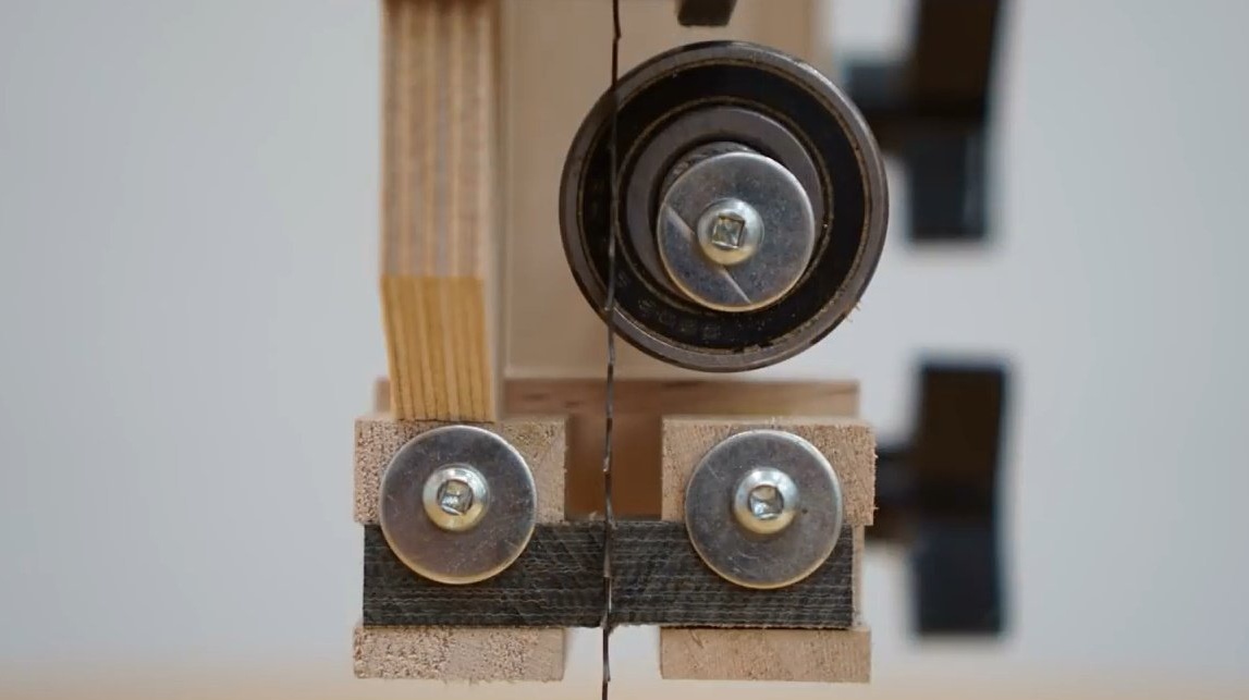
Then you can fit the graphite guide blocks. And the most remarkable thing about them is that they can almost closely touch the saw blade, i.e. no need to leave a gap.
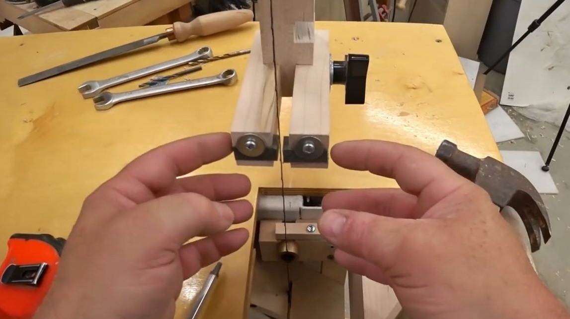
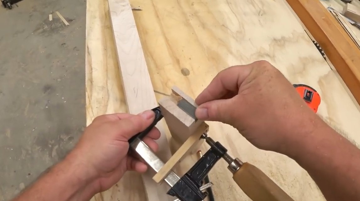
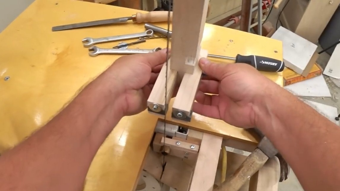
Having fixed the side stops with clamps, he drills holes in the rack.
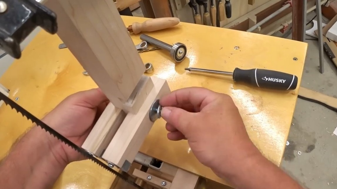
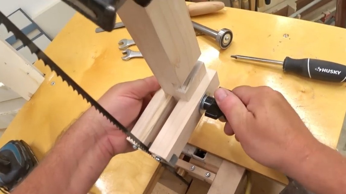
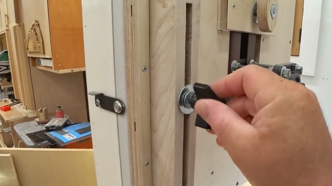
After that, the master makes a simple retainer for the thrust bearing, screws the bolt into the guide, puts on the clamp.
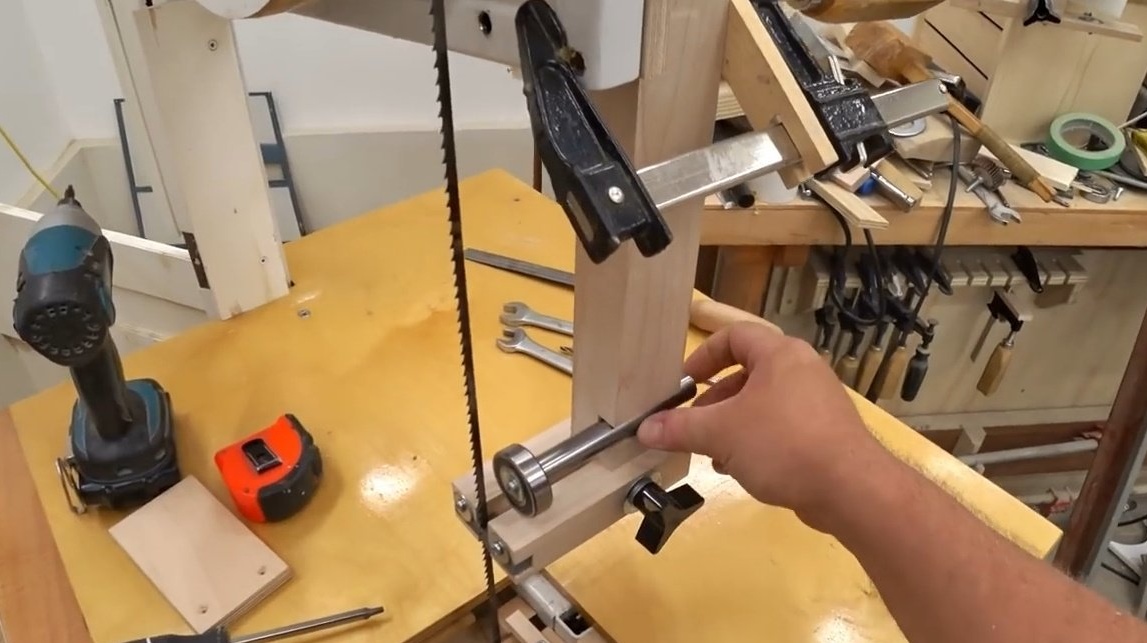
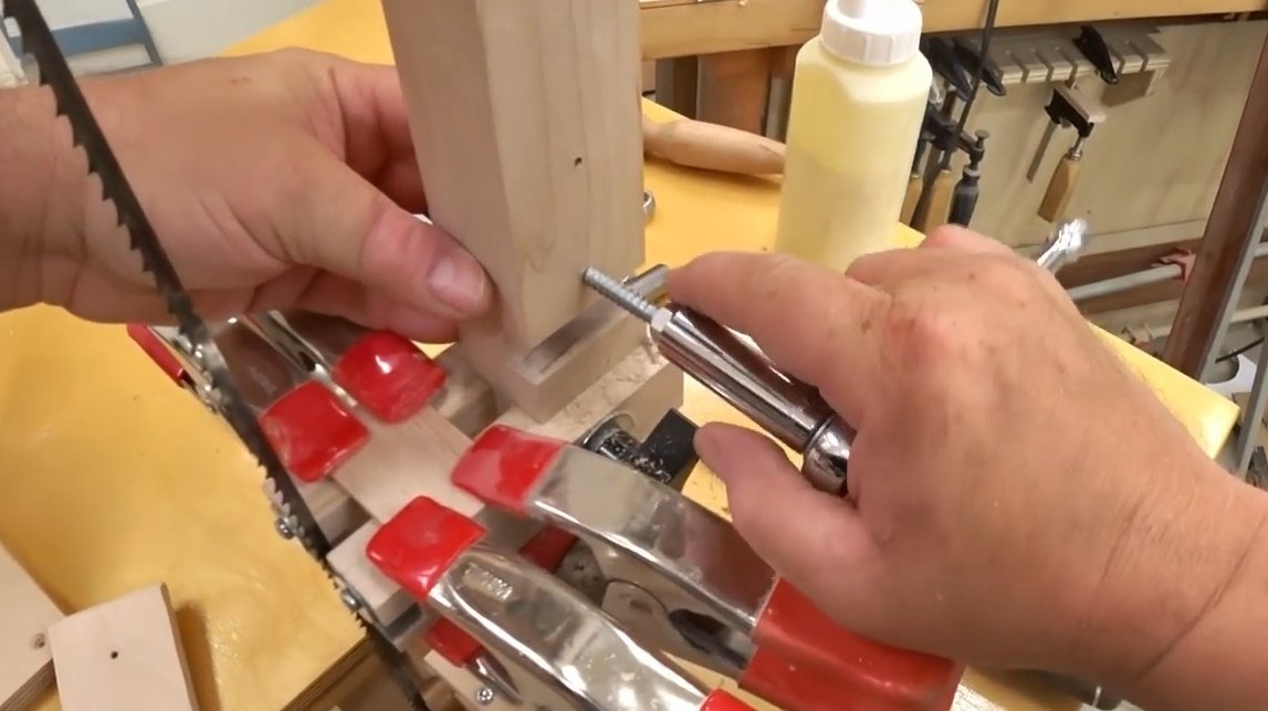
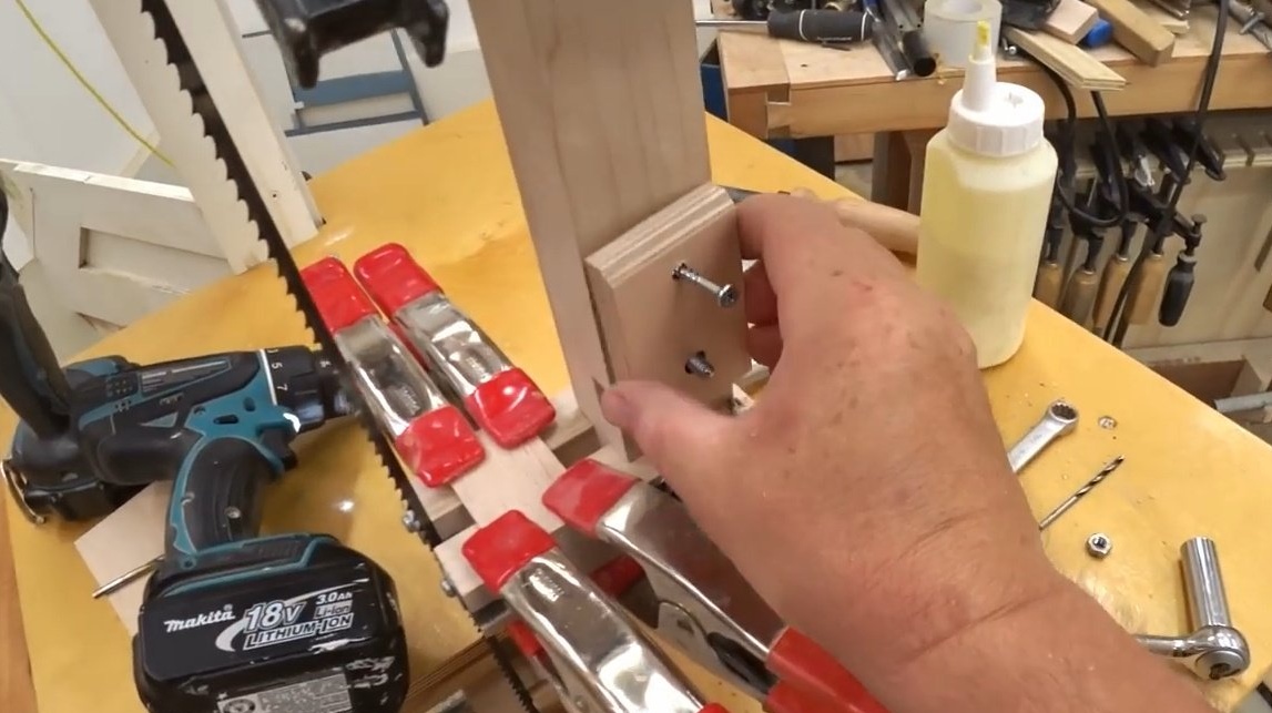
Now you can tighten the entire structure with the wing so that the shaft is clamped in the groove.
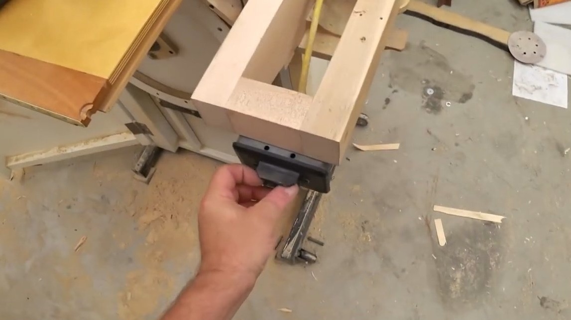
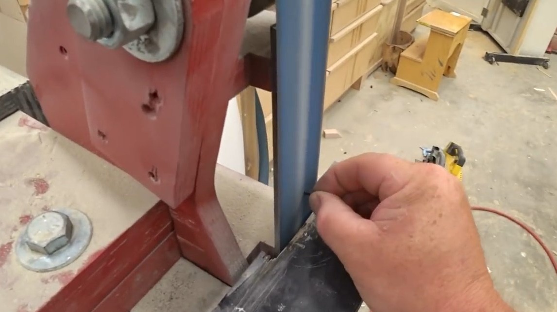
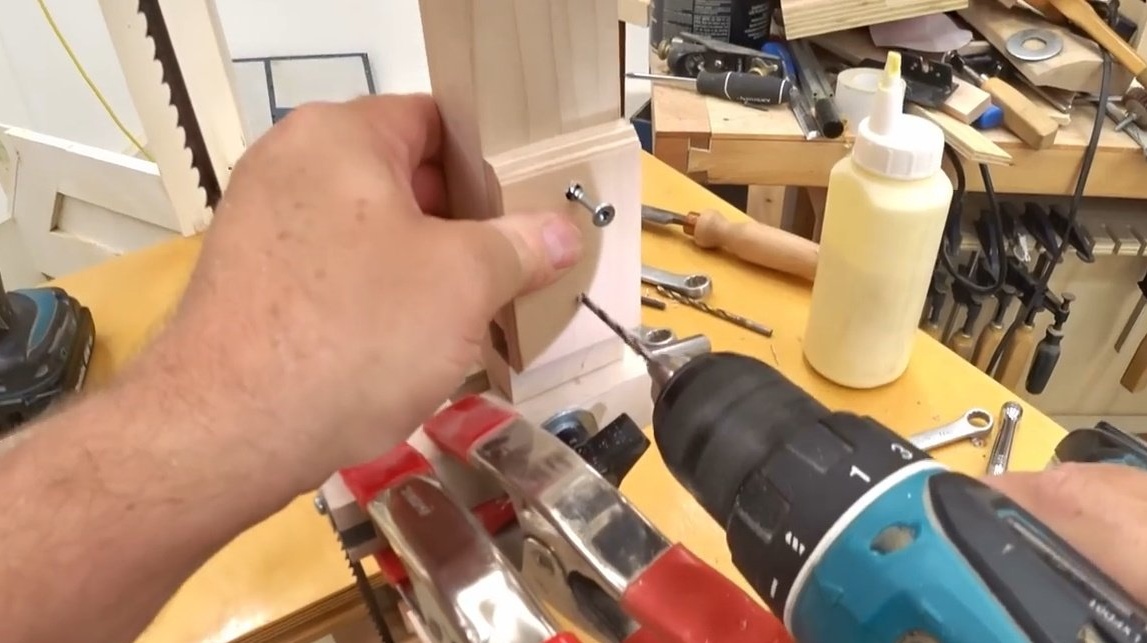
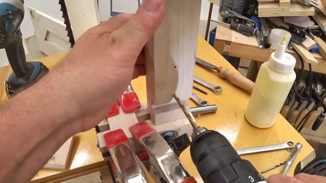
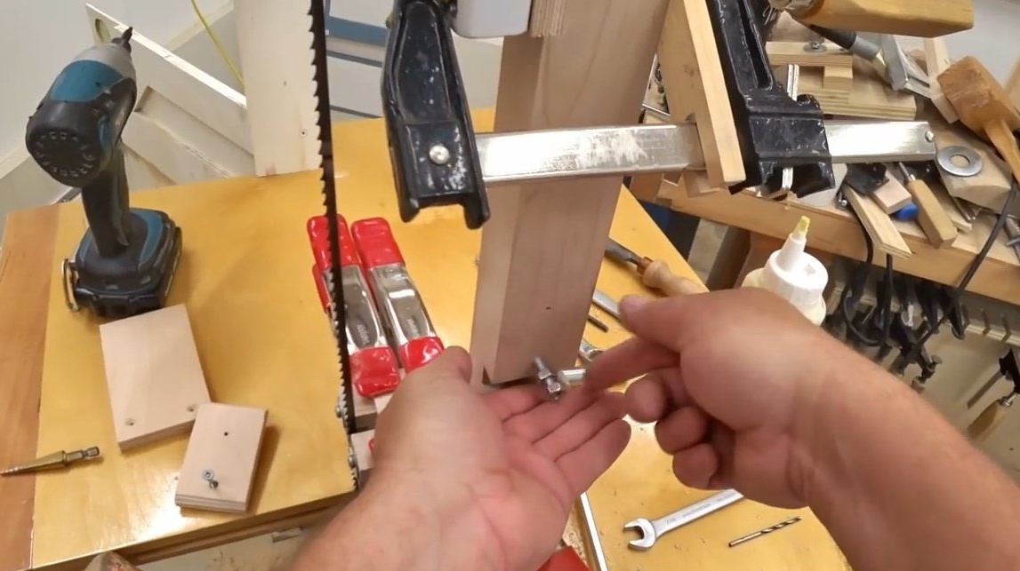
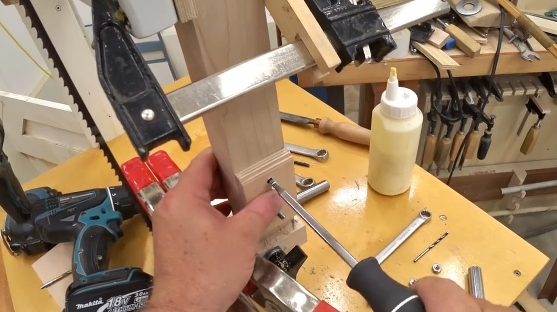
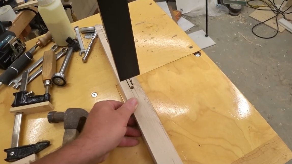
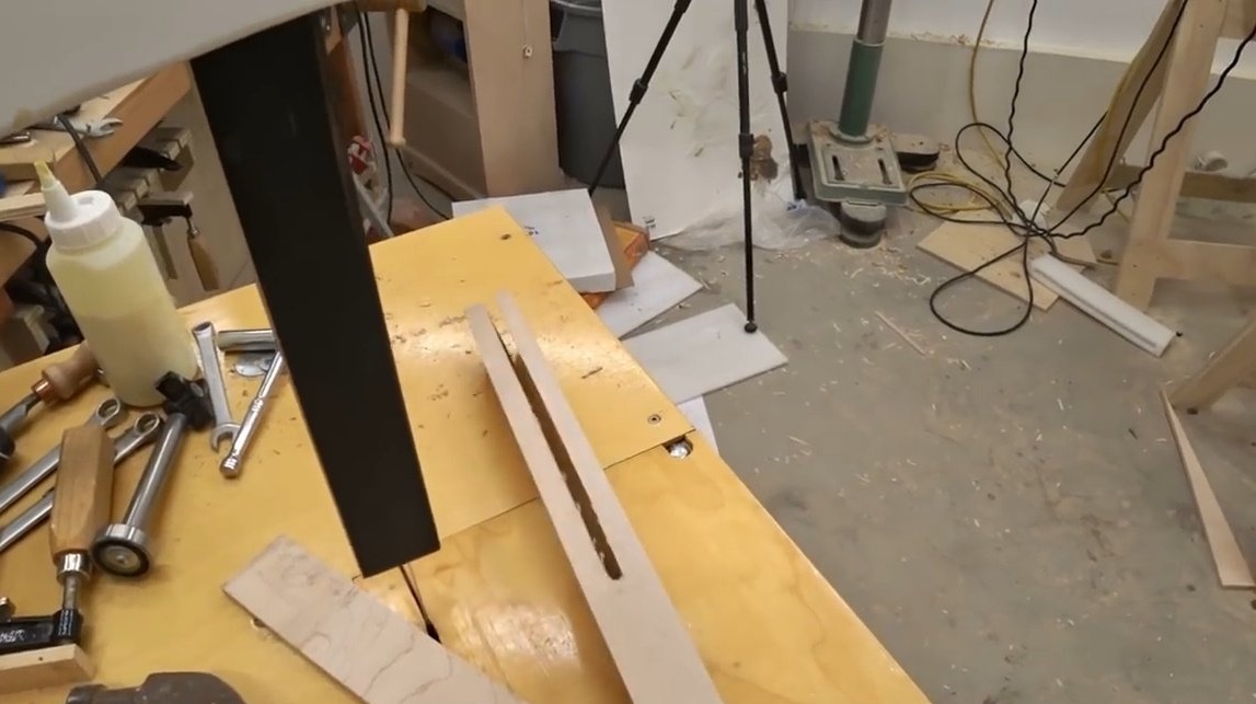
It remains to cut a groove in the main rack, for its vertical adjustment.
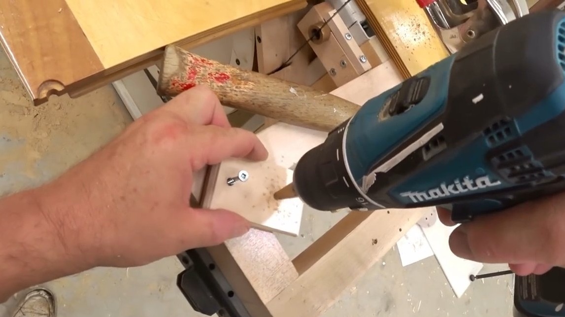
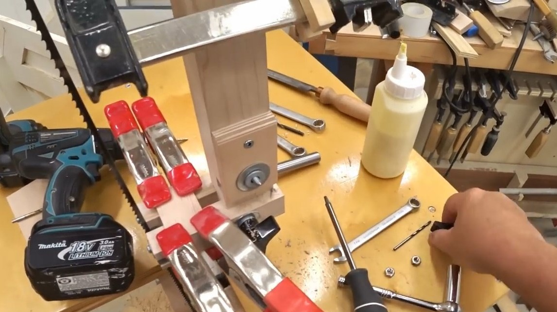
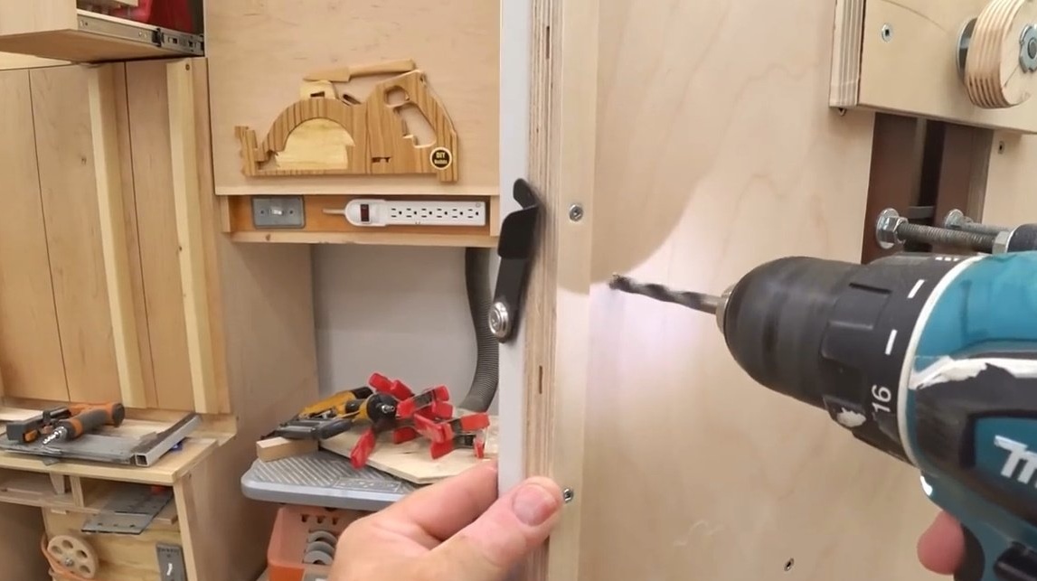
Drill holes, and attach the stand.
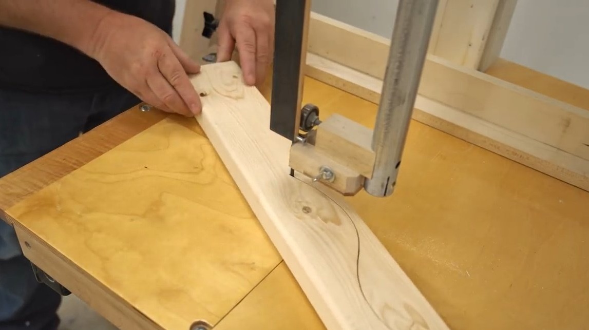
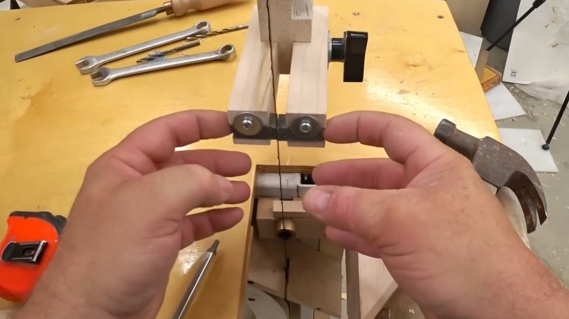
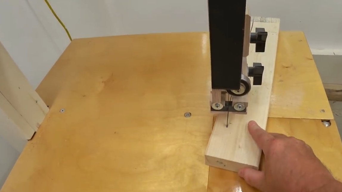
Everything is ready, you can check the modified machine in business. The saw blade now does not tilt to the side with curly cuts. And the cut is obtained strictly at 90 degrees.
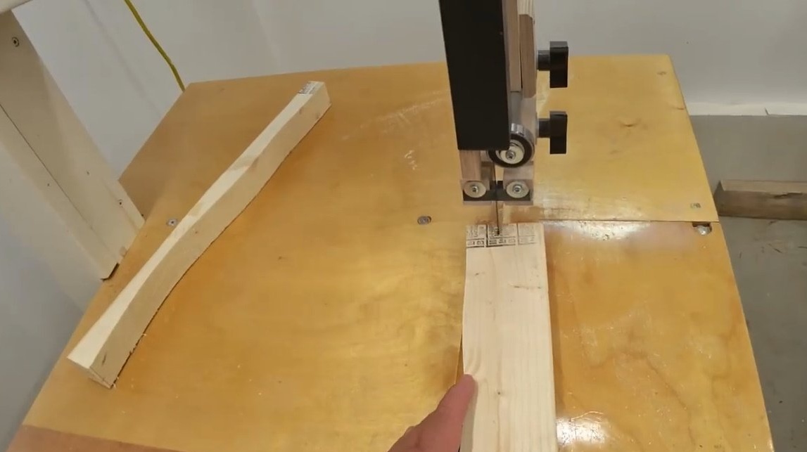
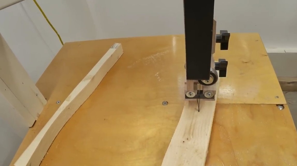
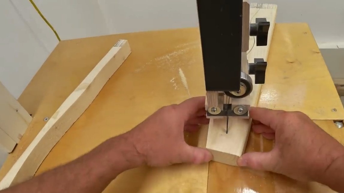
John is very pleased with such a revision.
Thanks to John for an interesting and useful revision of the machine!
Good luck to everyone, good mood and obedient tools!