
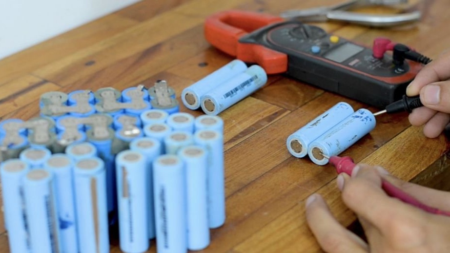
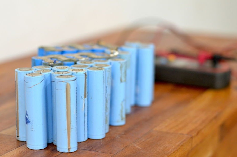
To motorize his bike, using a DC motor with a gearbox, the author needed a battery for this project. Therefore, in order to make a battery pack, the author decided to use the popular lithium-ion cells of the 18650 format from two old batteries of gyro scooters.
Since the cells are from used batteries, before making the battery pack you need to balance the charge of all the cells. Each time you use 18650 elements, you must go through this stage. But to balance the charge of all cells individually, so that their charge becomes the same, is a very long and not appreciative exercise.
And in order to effectively cope with this task, the author decided to create a special charger for 18650 cells. Moreover, he made it a modular charger, so that at any time you can add modules to form a larger grid, which will allow you to charge as many elements at the same time as you want.
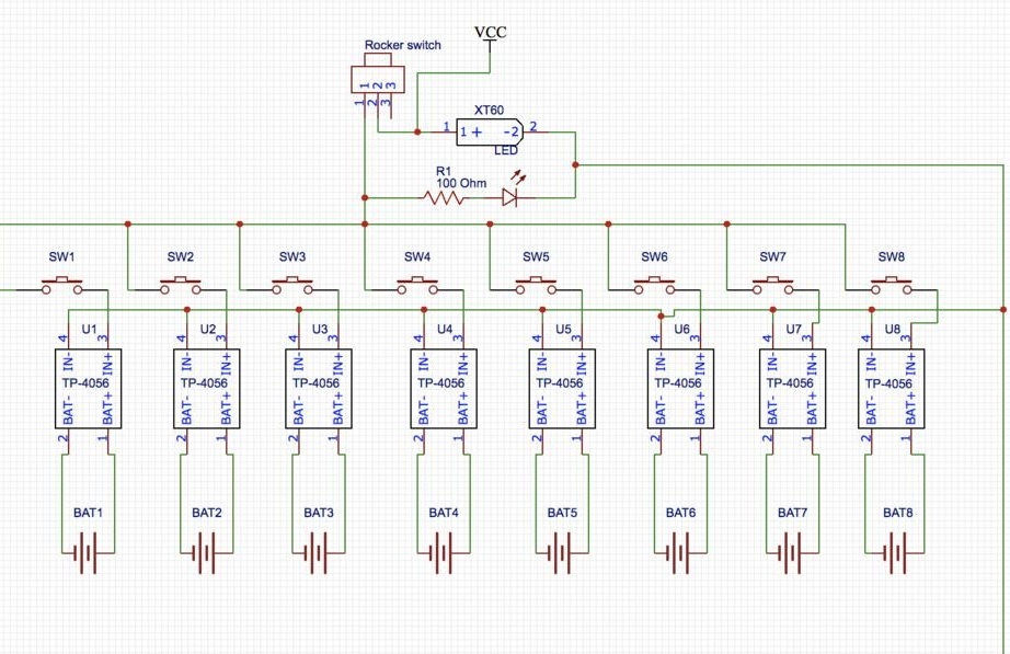
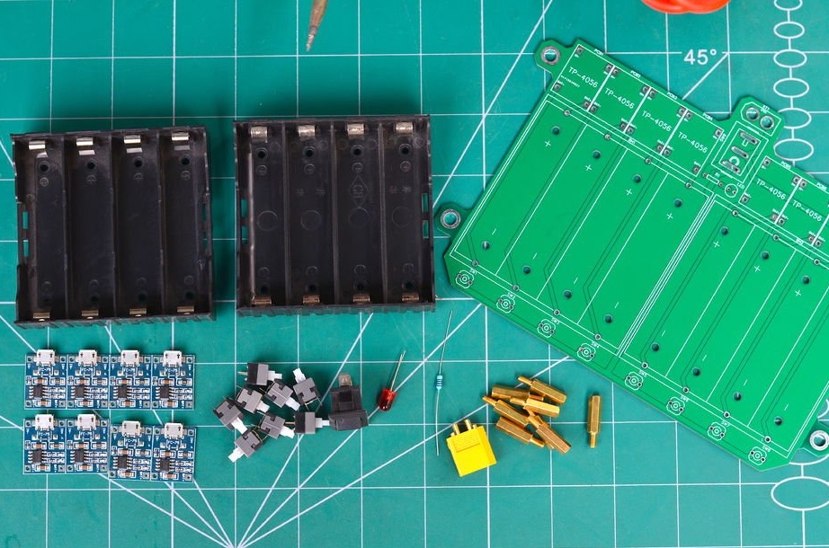
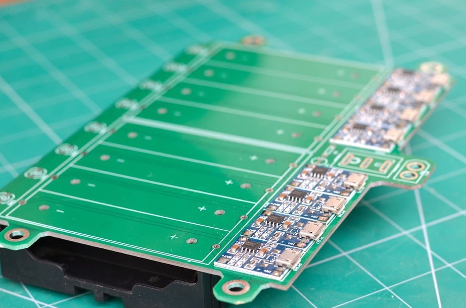
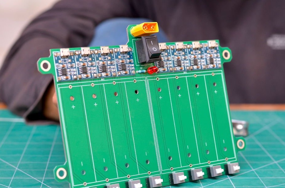
Due to the fact that the charger should be modular, easy to assemble and inexpensive, the author decided to use lithium cell charging boards. On Aliexpress, they cost 30 cents apiece. These boards are specifically designed for charging lithium-ion cells. The board has a micro USB input, they also have built-in overcharge protection, and, above all, they are very cheap.
For each module, two are used, each of which can accommodate up to four elements. Thus, for each module you will need eight TP-4056 modules.
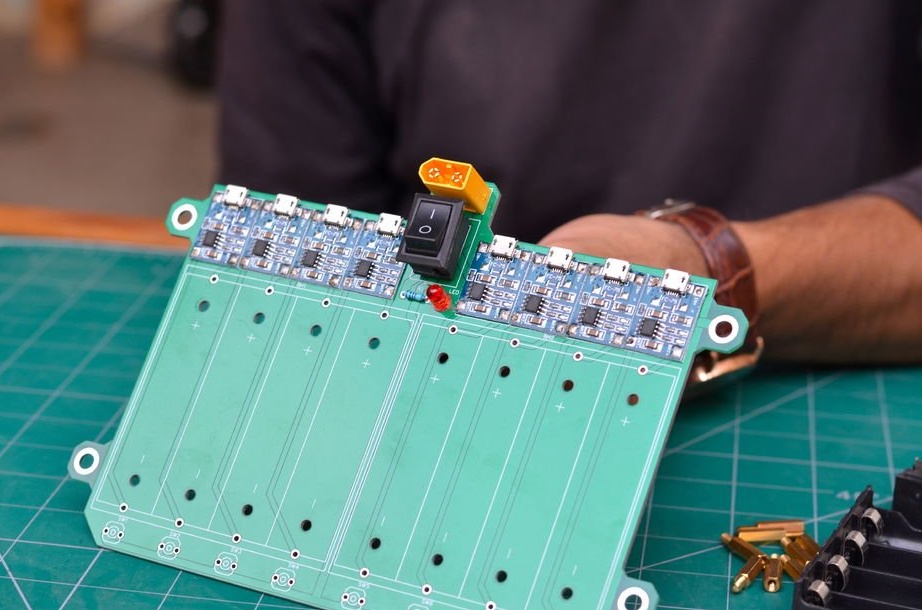
The XT-60 connector is used for the main power input of the board, but there is also an option for charging two or three cells only with the help of a charger for cell phones.

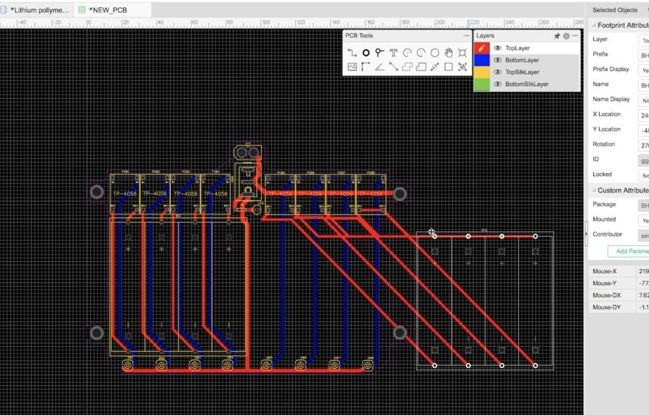
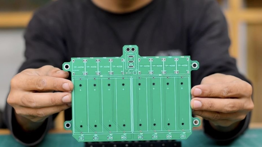
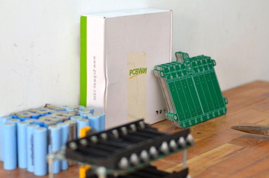
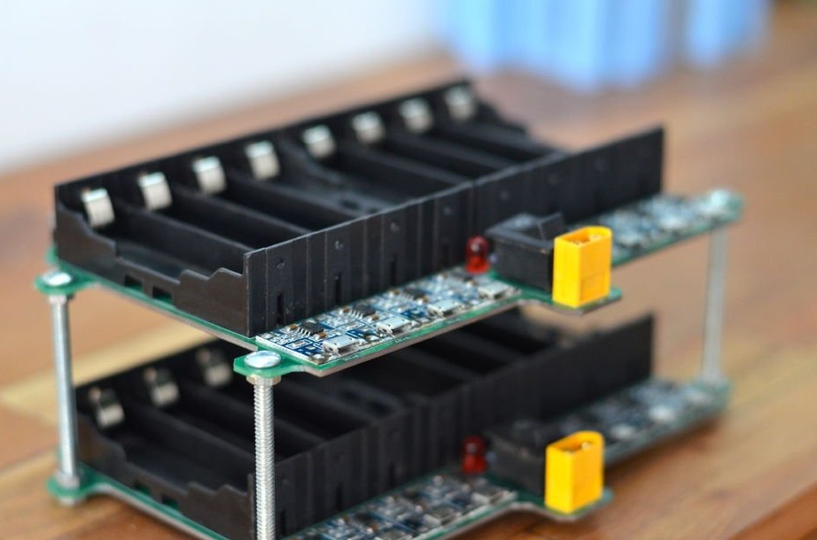
In order for everything to look neat and easy to assemble, PCBs were designed.
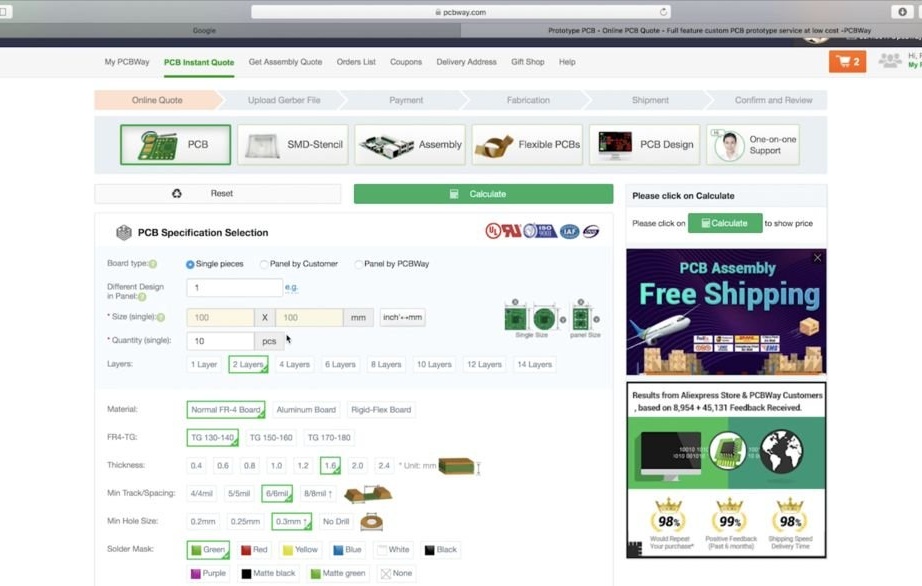
To save time, you can order printed circuit boards from some manufacturer, or you can order them on, as the author did, ordering 10 immediately. These boards will be enough to build a charging grid that can charge up to 80 cells at a time.
After you download the Gerber files, wait for the PCB design to be checked to make sure that the prints are OK. They make quality printed circuit boards not expensive. To get discount coupons for printed circuit boards, go to
Within a week, the circuit boards were ready.
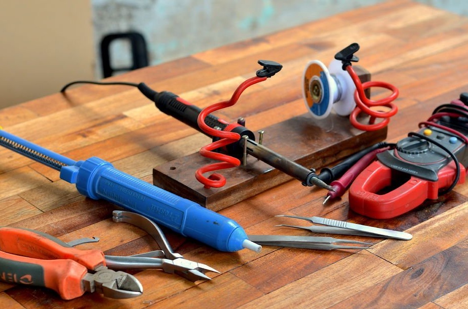
For the project you will need
• Soldering iron
• Solder
• pliers
TP-4056 Modules
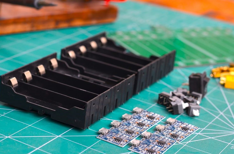
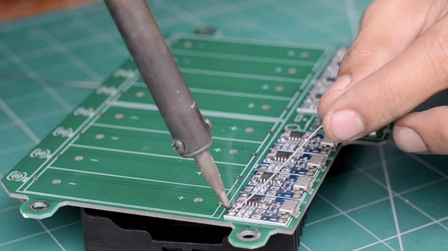
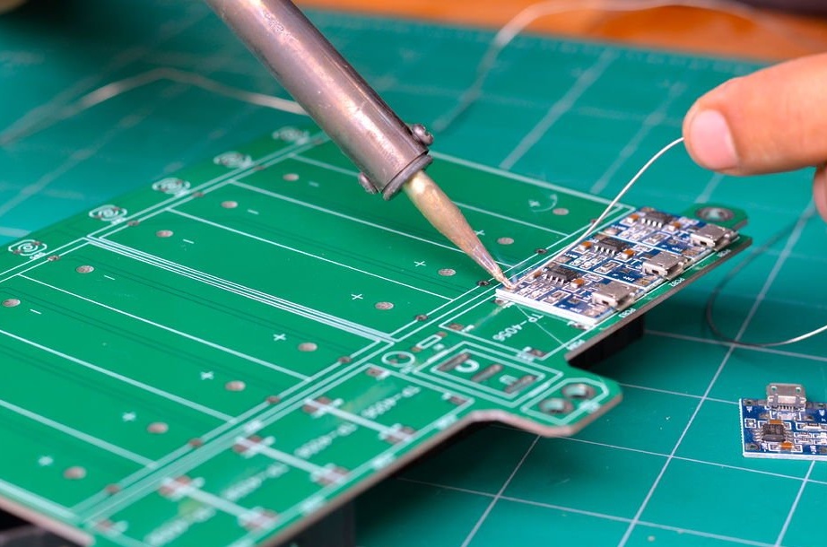
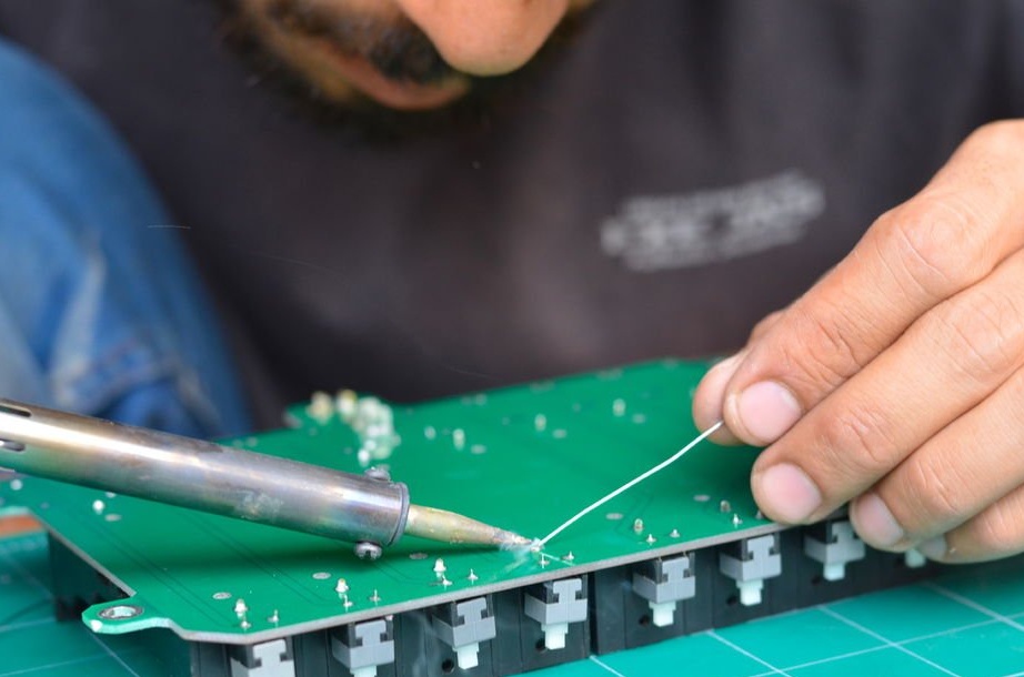
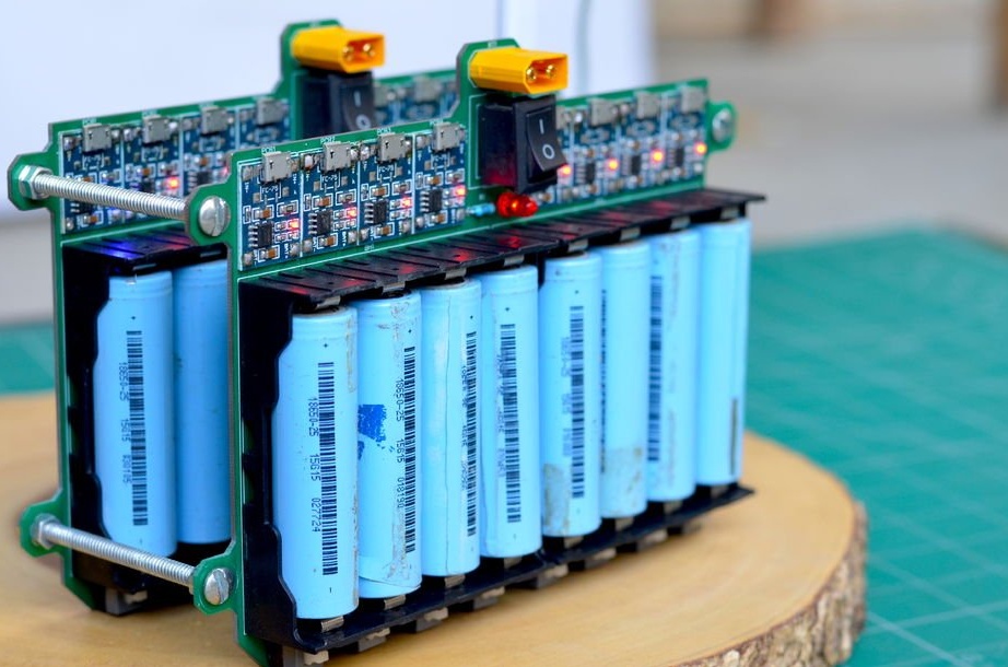
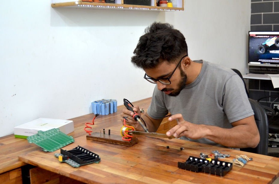
To assemble the circuit board, all we need to do is place all the components, as indicated, on the circuit board. Start by soldering the charge cards, and then move on to larger components.
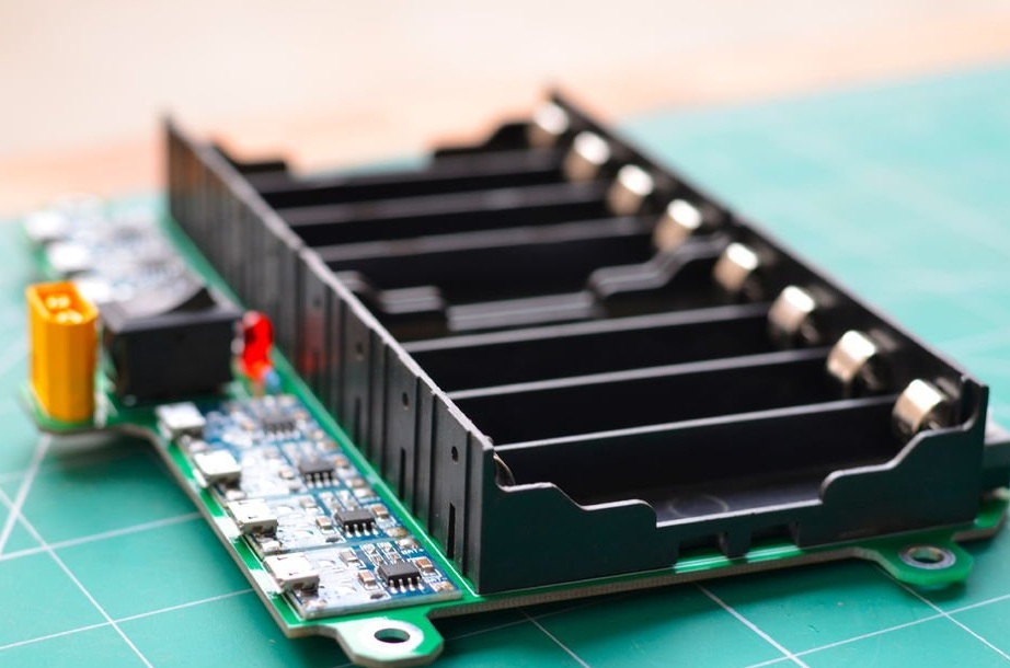
When you finish soldering all the small components, solder the cell holders. Be sure to observe the polarity on the cell holders indicated on the printed circuit boards.
To completely solder all the components on one module, the author took about 10 minutes. Before assembling the following modules, check the one you did.
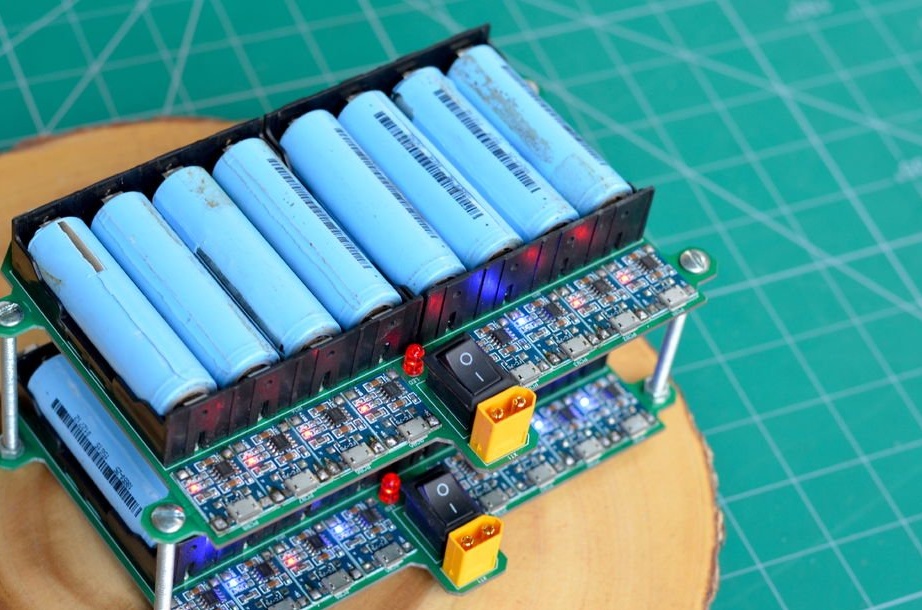
Now, to test the module, connect the charger from the cell-phone to the TP-4056 board using the micro USB cable. This allows you to charge up to three cells.
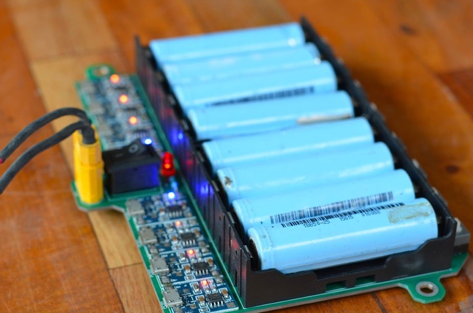
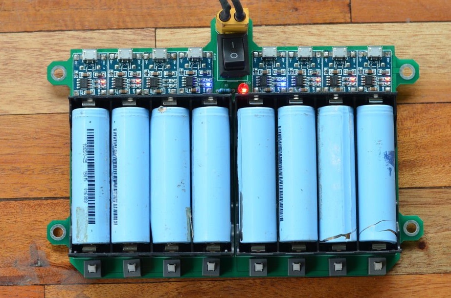
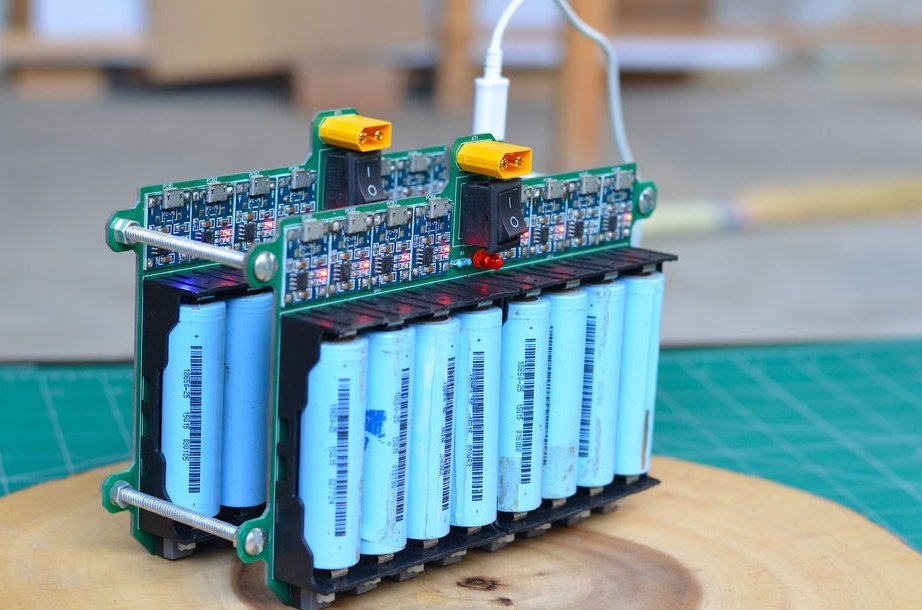
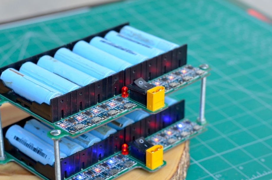
To charge eight cells, use the 5V output of a PC power supply with an XT-60 connector. The module charges each cell flawlessly. When the battery is fully charged, the light on this charging board will change from red to blue, and you can turn off the power of this particular battery to save energy.
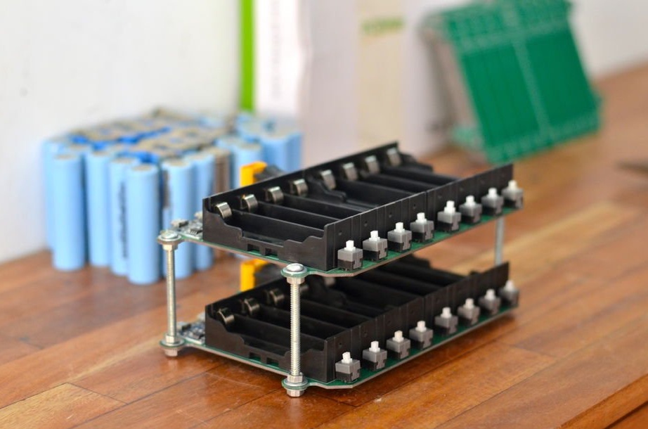
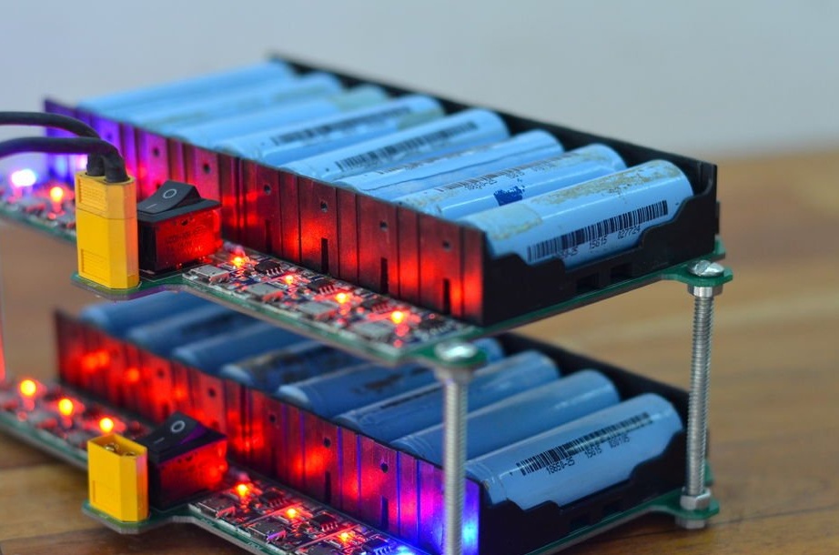
Next, make as many charging grids as you plan to charge the batteries at the same time. You can use the same power source as in the previous step to power all the modules. Since each module is connected in parallel through a jumper, supplying power to the input of any module will provide power to the entire network.
Now you have a charger that can charge as many cells as you need, and its price is much lower than similar professional devices.
Project Files: