
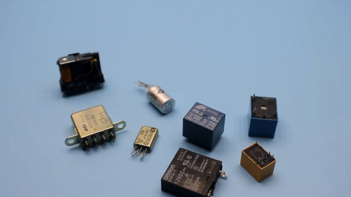
Today we’ll talk about a conventional electromagnetic relay. Simple in execution is not very durable and seemingly unremarkable relay. The author of the AKA KASYAN YouTube channel will tell you where and for what purposes it can be used and what simple, but very useful constructions can be built on its basis. By the way, this material is sharpened for a beginner radio amateur. Well then, let's get started.
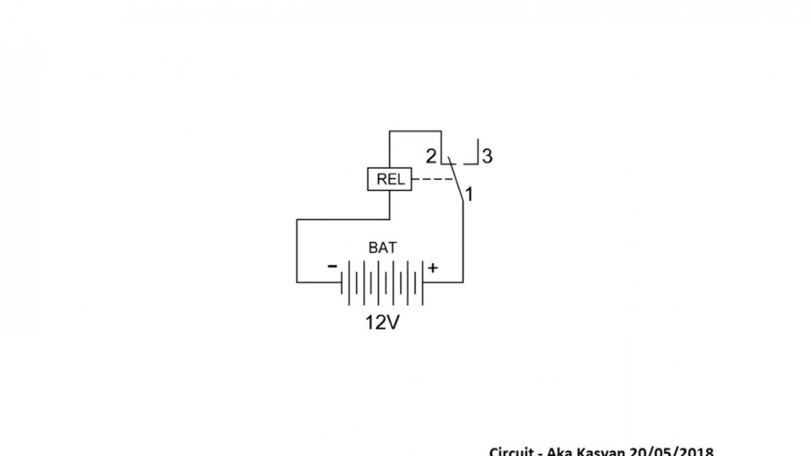
Our first circuit built on the basis of a relay and an electrolytic capacitor.
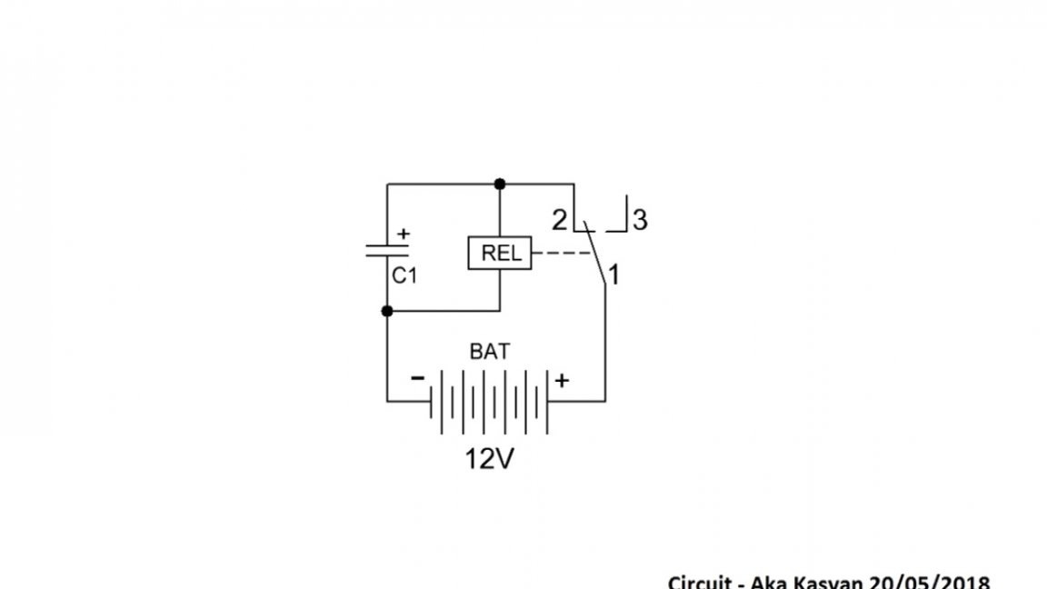
In order to understand what it is intended for, first let's understand how this whole thing works. Power, for example, 12V via the power contact of the relay is supplied to the positive lining of the capacitor and simultaneously to the coil. The minus or the mass of power comes directly, bypassing the contacts.
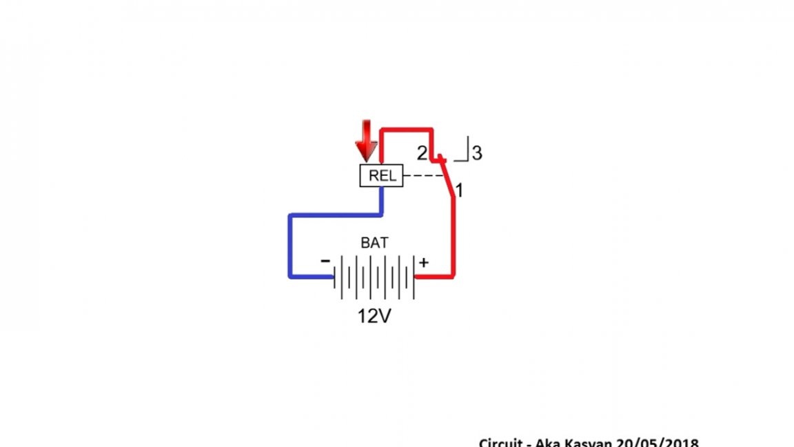
Initially, prior to powering up, these relay contacts are closed.
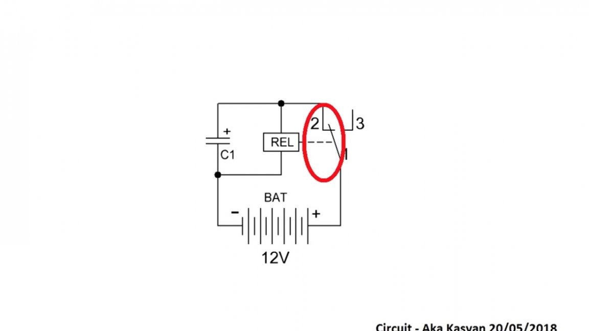
As soon as the power is supplied, the relay is activated, contacts 1 and 2 open, instead, contacts 1 and 3 are closed.
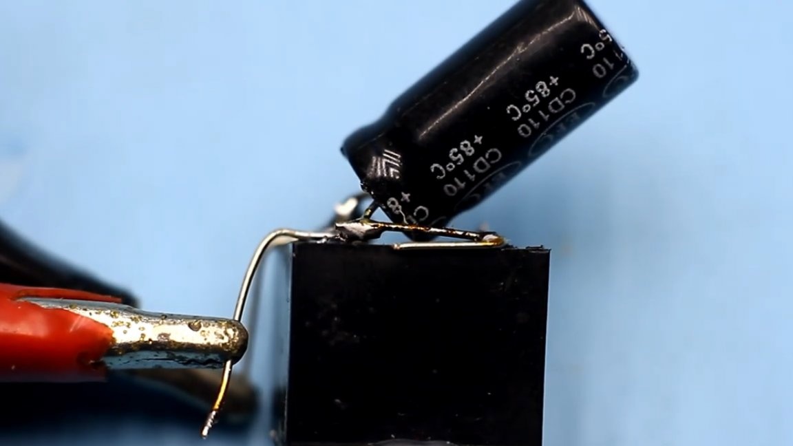
But by that time, enough energy had accumulated in our capacitor, and the energy stored in the capacitor was supplied to the coil. As long as the voltage across the capacitor is sufficient to power the relay coil, the contacts will be in this state.
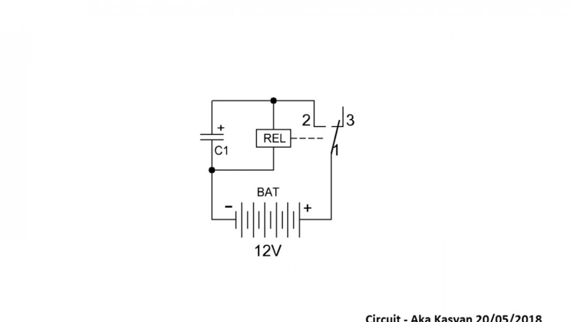
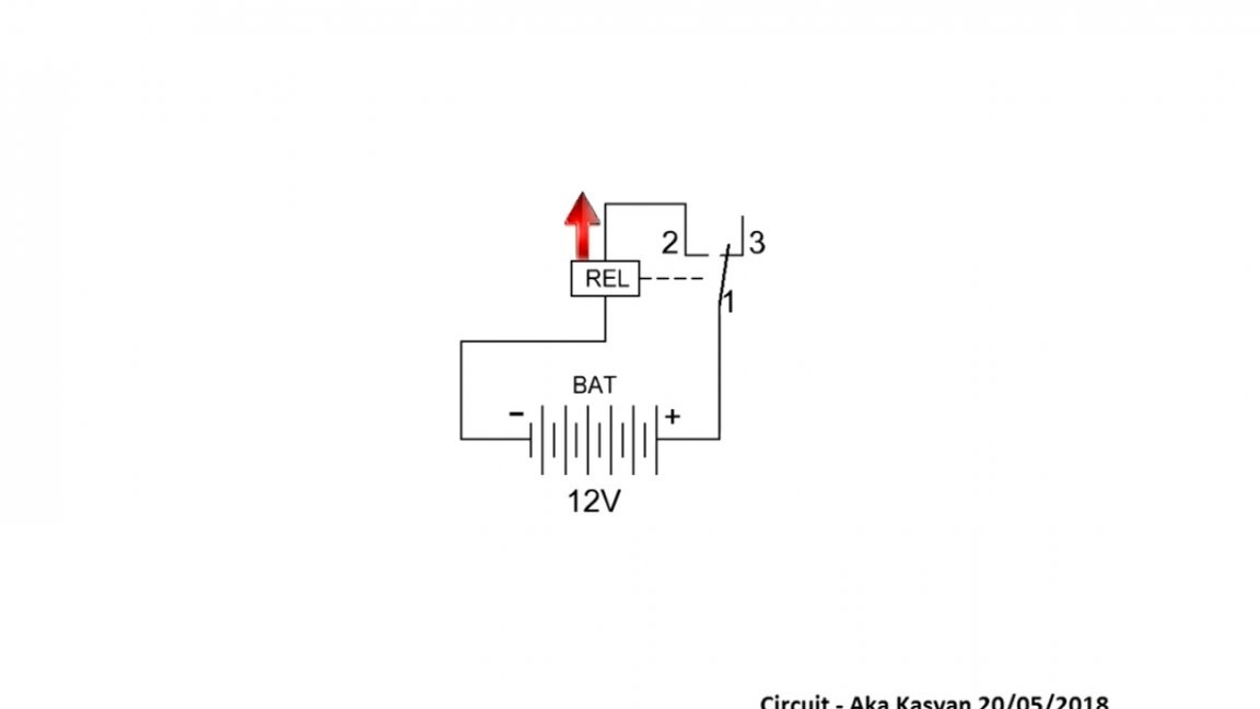
Over time, due to the discharge of the capacitor, the solenoid in the composition of the relay becomes unable to hold the contacts in this state. The relay turns off and the contacts return to their original state. Again, the capacitor is charged, the relay is activated and the process repeats again, that is, the relay periodically changes its state, then on, then off.
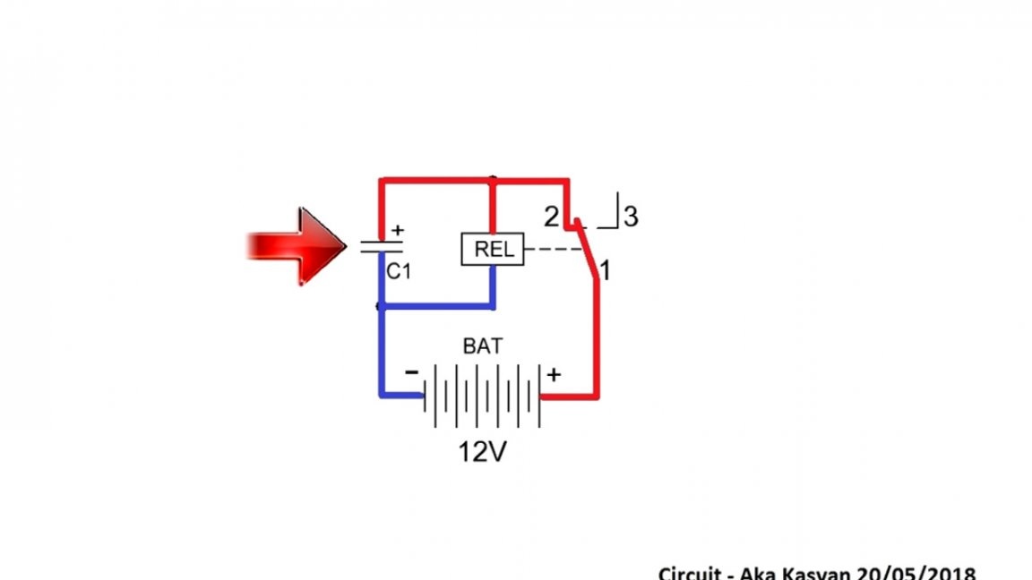
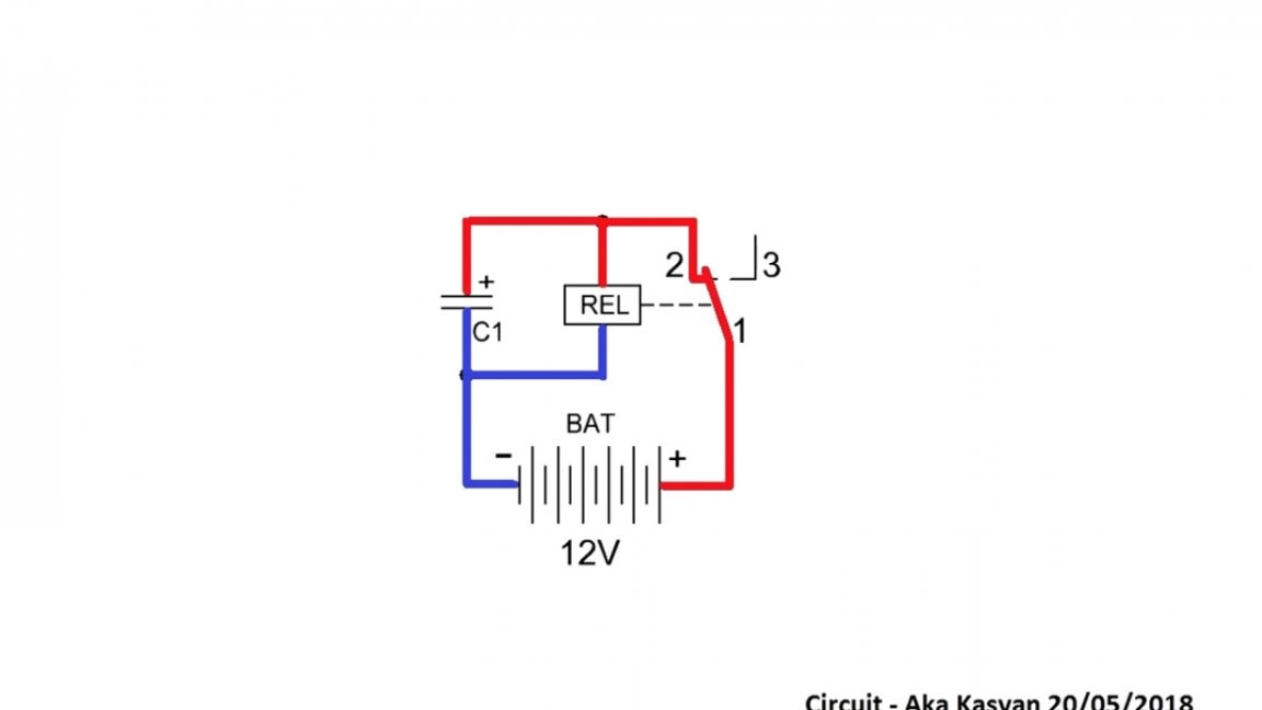
The on / off intervals depend solely on the capacitance of the capacitor. The larger the capacitance, the longer the solenoid will hold the contacts and vice versa. There are several ways to connect the load to our breaker: 1) to break one of the power wires;
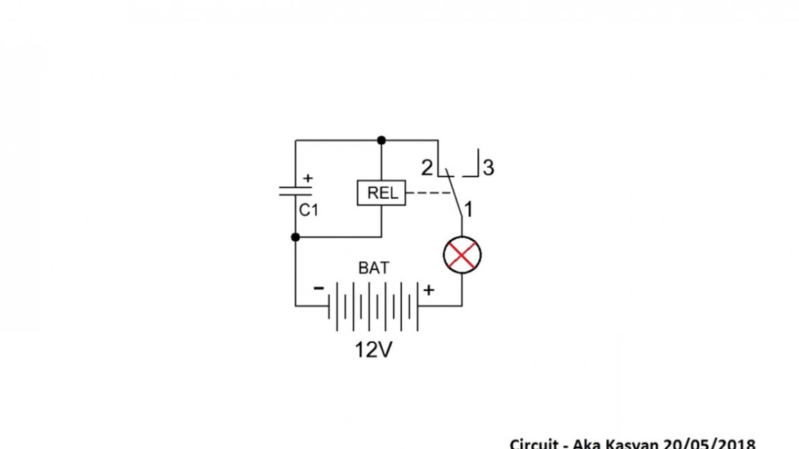
2) use the 3rd relay contact;
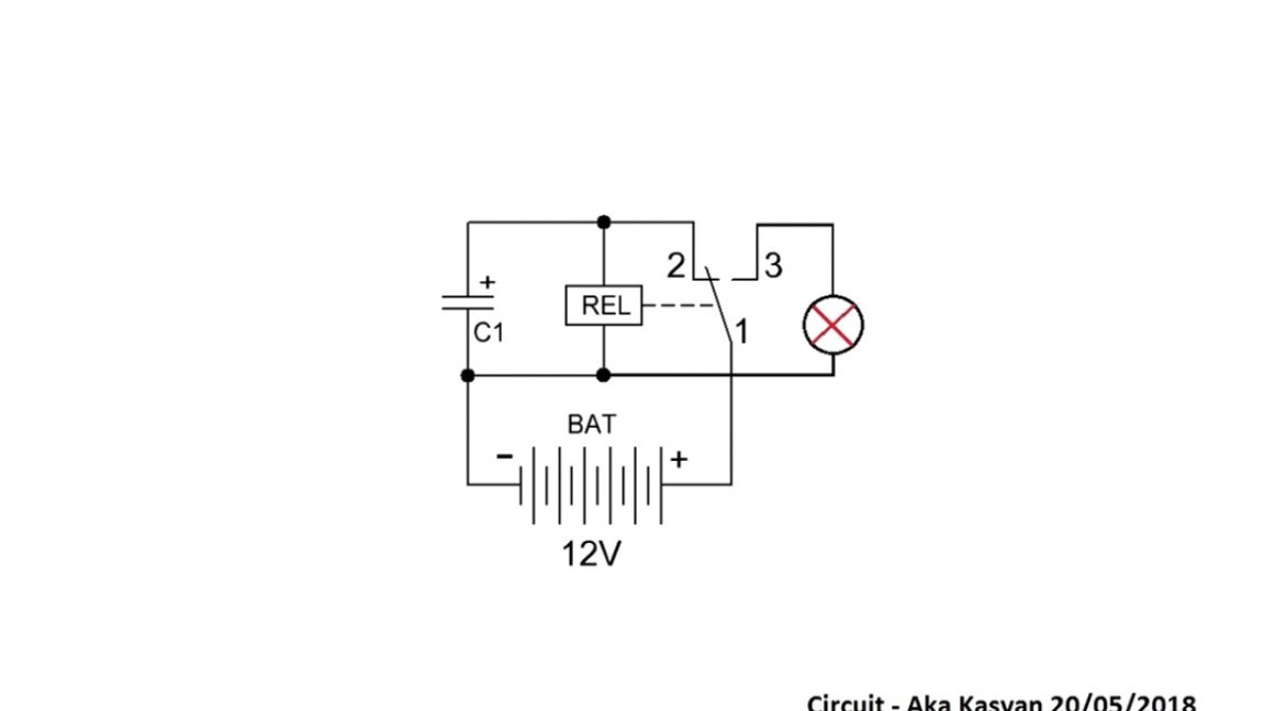
3) use a relay with 2 contact groups.
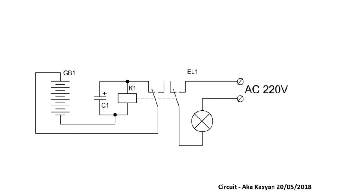
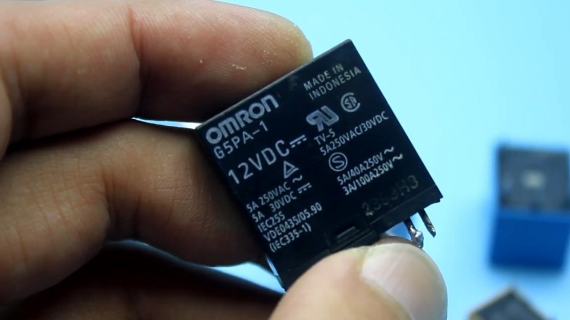
The first 2 options have several drawbacks. Firstly, it is impossible to connect loads of high power and, secondly, these decisions will affect the operating frequency of the circuit. The third option is the most correct, since the contacts that will carry out the switching of the load are not connected in any way with the control contacts, which makes it possible to connect any loads, including network loads, to the circuit.The power of the connected load depends solely on the bandwidth of the relay, that is, on the current allowed through its contacts. This parameter is indicated on the relay case, as well as the voltage of the solenoid.
This circuit, as well as all subsequent ones, is so simple that it makes no sense to make it on a printed circuit board. And so, if you are fond of electronics and want your homemade products to look like a factory product, then you can order a board from the Chinese.
The second scheme is a little more complicated.
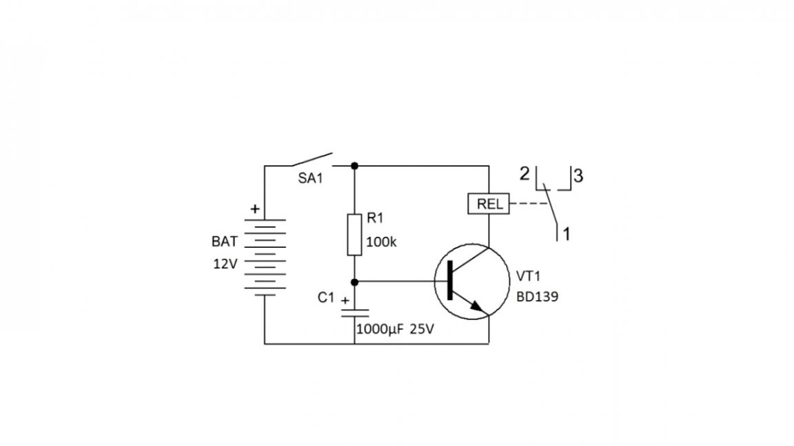
Here, in addition to the capacitor, 2 more components are added - a resistor and a transistor.
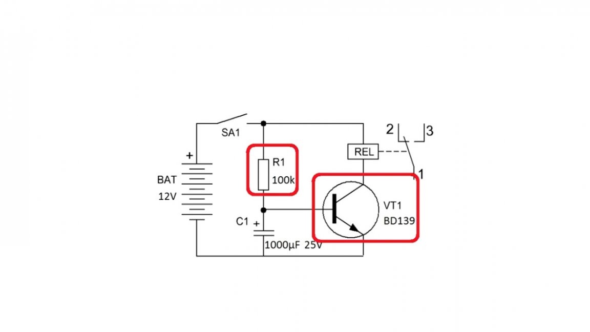
A transistor of almost any, small or medium power, reverse conductivity. This circuit is a delay system when turned on, something like a time relay. When power is applied to the circuit, the relay does not turn on immediately, but after some time has passed. At the initial moment, the capacitor slowly charges through the limiting resistor.
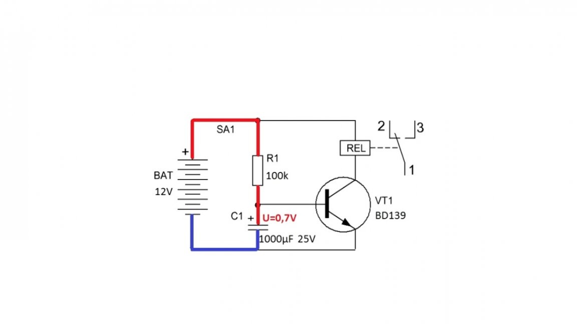
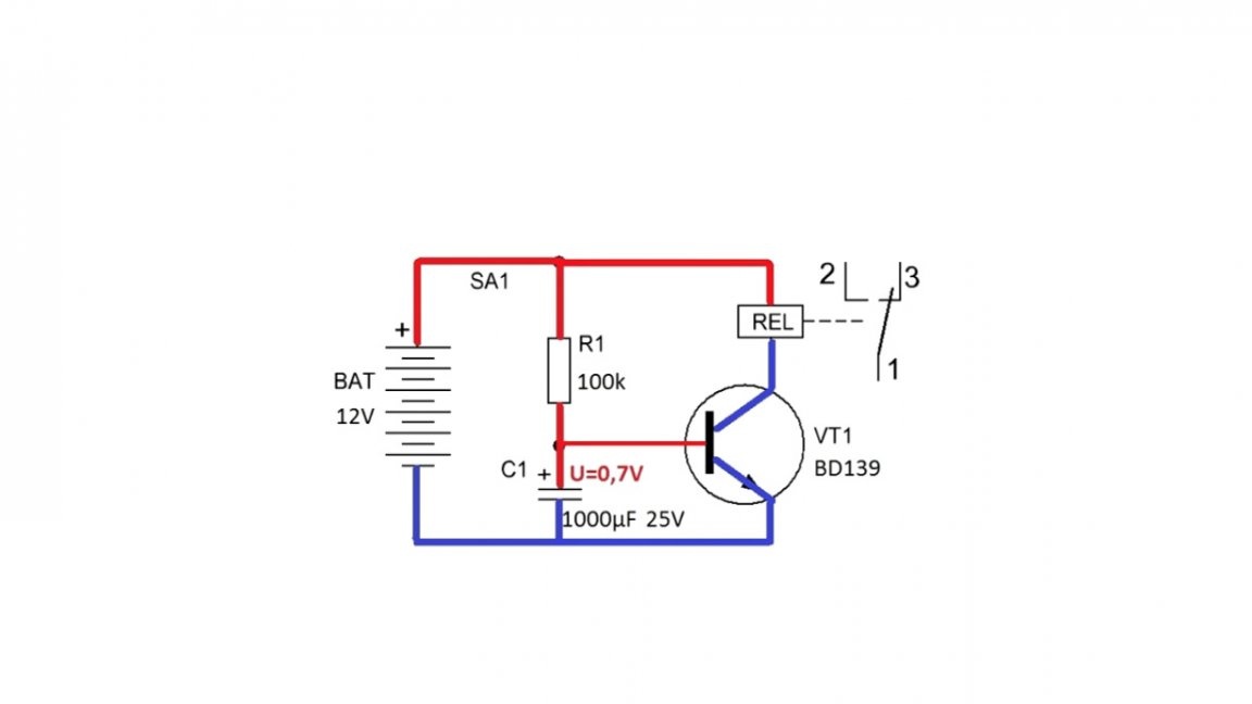
As soon as the voltage on this capacitor reaches a certain value (somewhere 0.6-0.7V), the transistor trips. By its open transition, power is supplied to the relay coil. The relay operates by switching the load.
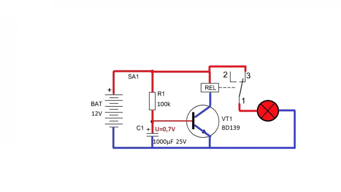
The delay time depends on the capacitance of the capacitor and the resistance of the resistor. The greater the capacitance and resistance, the greater the delay and vice versa.
The following diagram:
It may seem that the author forgot to draw some components, but to build this design, in addition to the relay, we do not need anything else. The principle of operation is the same as that of the first scheme. The power is supplied through a closed contact to the solenoid, it is triggered, the contacts open, the power supply stops, and since the solenoid is de-energized, the contacts again return to their original state.
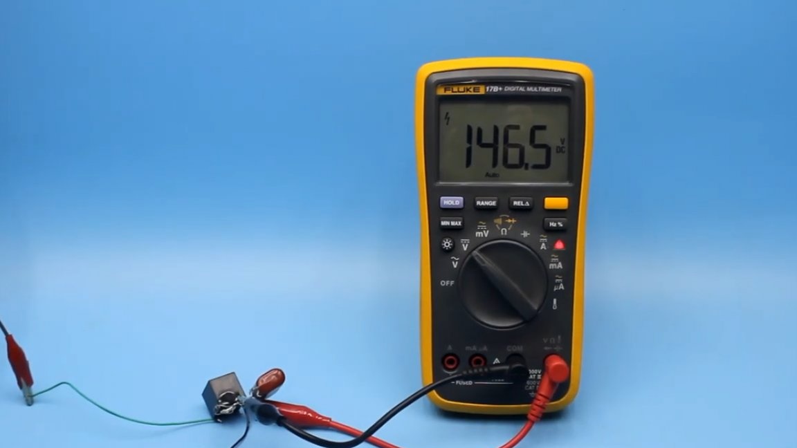
Such a converter is practically uncontrollable. The operation occurs with a rather high frequency and it must be said that the standard relays do not last long in this mode. But the meaning of this scheme is still there. The fact is that the phenomenon of self-induction is characteristic of inductive loads, and our solenoid is just the same inductance. What's the catch? At the moment when power is supplied to the solenoid, it seems to accumulate some energy. When the supply circuit opens, the solenoid gives up the accumulated energy, while the self-induction EMF is much higher than the supply voltage.
Even with a 9-volt Kron battery, the self-induction voltage of the solenoid reaches several tens or even hundreds of volts.
But do not be afraid, it is not dangerous, but getting an unpleasant electric shock is still possible. If we add a rectifying diode and a storage capacitor to our circuit, we get something similar to a stun gun.
Everything is simple here. The chopper provides periodic supply of power to the solenoid, after turning off the power, the self-induction voltage through the rectifier is accumulated in the capacitor. A capacitor is required at 250 or 400V. Due to the small capacity, a few seconds of the circuit is enough to charge the capacitor.
The energy accumulated in the capacitor can perform a useful action, well, or not quite useful. Of course, such a thing cannot be used as a shocker, but it hits quite unpleasantly.
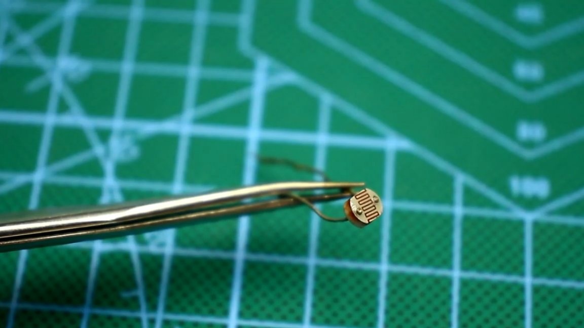
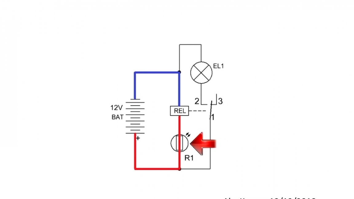
An interesting version of the photo relay can be built on just 2 components: a photoresistor and a relay.
The photorelay, which can be found on the network, even the simplest options include a transistor and a pair of resistors.
It is correct, such schemes are more practical, but the presented option also has the right to life. A photoresistor is the most common, its resistance in the dark is very large, in daylight it is reduced to several hundred ohms.
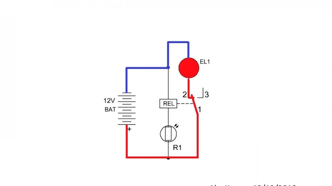
The principle of operation is as follows. In the afternoon, when it is light, the resistance of the photoresistor is minimal and the relay operates, opening contacts 1 and 2. A load, such as a lamp, is turned off.
With the advent of darkness, the resistance of the photoresistor begins to increase, therefore, the current in the relay coil decreases, and at some point the current will not be enough, and the relay contacts will turn off. In this case, contacts 1 and 2 are closed, and the load (the same light bulb) will work by illuminating the courtyard or path.
The disadvantage of this circuit, unlike those that have at least 1 control transistor, is that this option does not have the ability to adjust.
At this time it is time to round off. Thank you for attention. See you soon!
Video: