
Today, together with Roman, the author of YouTube channel "Open Frime TV", we will assemble a platform levitron.
The history of the creation of this device began back in 2016. Then the author stumbled upon an article of "BrainChinov", and with all my heart fired up to repeat this device.

But not everything is so easy. It was not possible for the author to collect just such an option. Then he began to look for an alternative and found one on RadioKot.

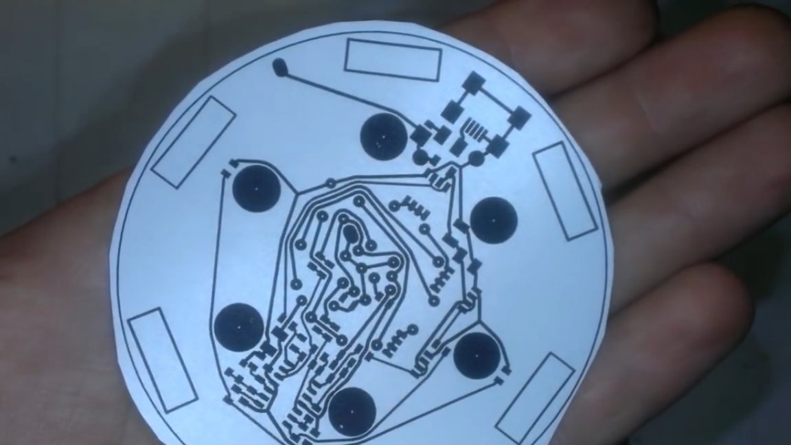
I downloaded the signet, began to poison, and then assemble the device.
But in the end, everything broke off. Six months later, maybe a little more, the author began to master Arduino. And the idea came to him to make a levitron on it. With renewed vigor, he rushed into battle, but again disappointment. Many sleepless nights in code writing and assembly were in vain. The levitating magnet still did not want to hang, it was pulled from side to side and that's it.
After some time, the author came across another article with a full description, ordered components, began to assemble, wound new coils, started everything and again failed. The author began to think why the Levitron did not start and realized what the problem was. It turned out that all the wound coils had a metal base inside, and the force with which the magnet reached the core exceeded the reaction. Because of this, such crap happened. As a result, the author rewound the coils and a miracle happened - the magnet flew.
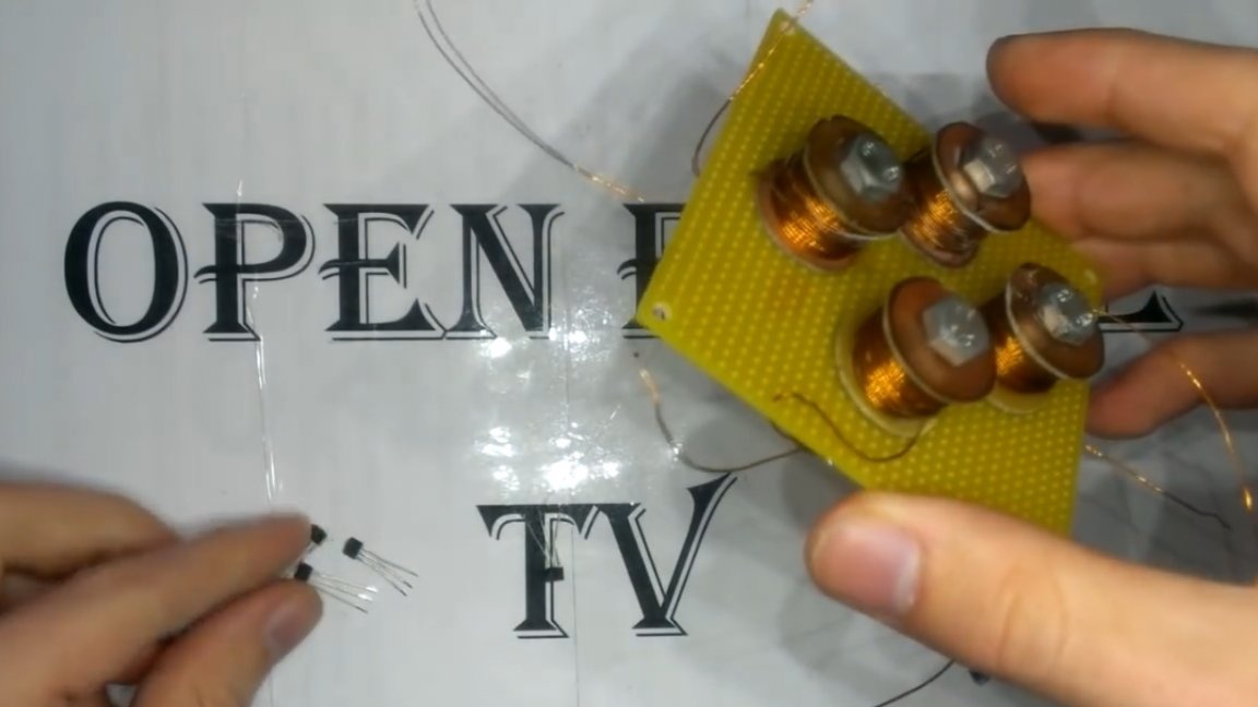
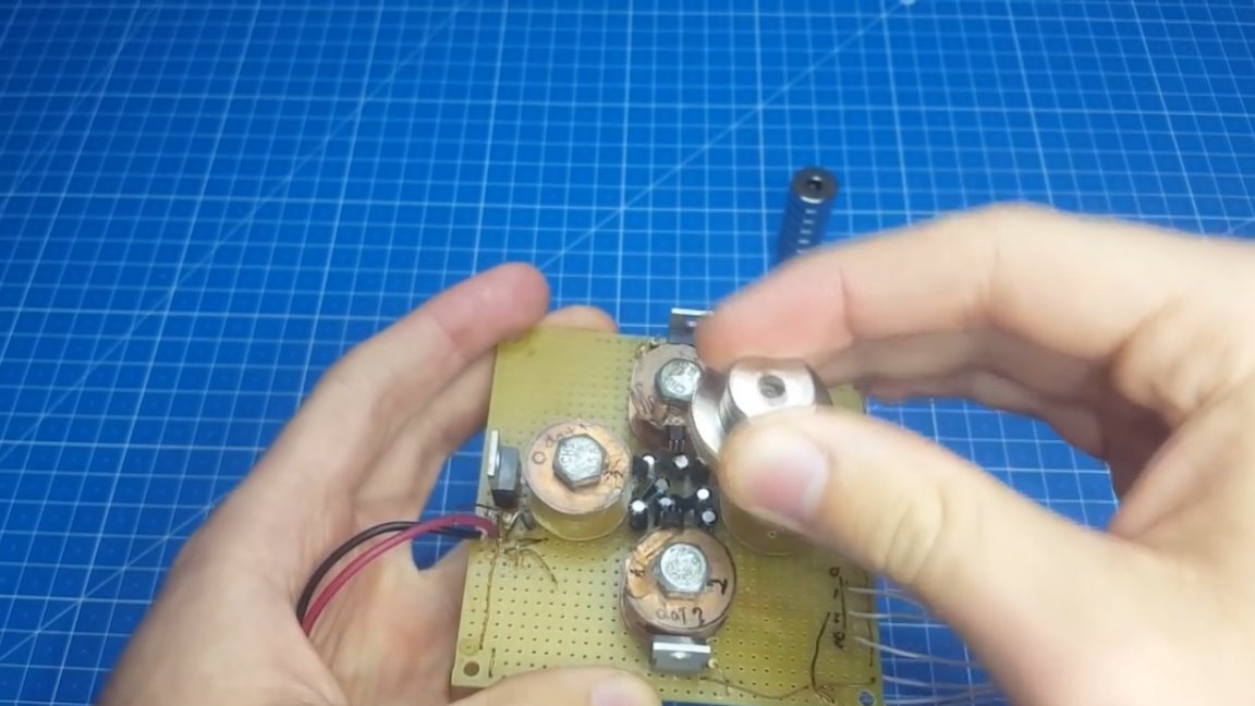
Joy knew no bounds. The author admired his homemade product all evening. Well it was like that, the background, but now we proceed directly to the assembly. First, let's get acquainted with the device.
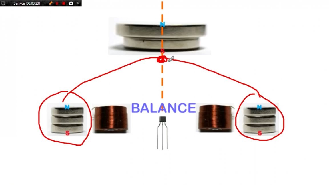
So, at the base we have permanent magnets that create a magnetic field in the form of a dome. At its very top there is an equilibrium point, at this point the base magnets seem to push the levitating magnet up, compensating for the force of gravity. But there is one “but”, this point is extremely unstable, and the levitating magnet constantly flies from it.
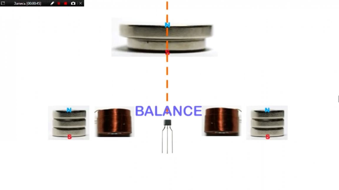
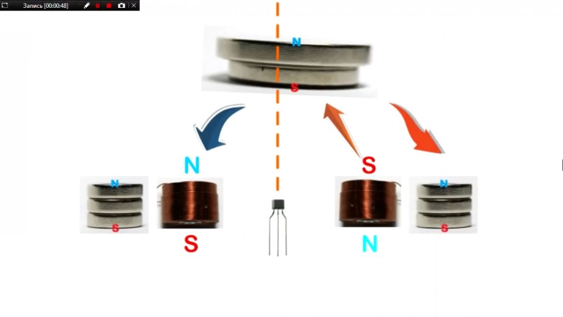
Here, electromagnets and Hall sensors come to our aid, which track the position of the magnet and as soon as it starts to fly away from the point, the corresponding electromagnet turns on and pulls the levitating magnet back to the center. Thus, he makes oscillations in different directions, but with great frequency, and the eye practically does not see it.
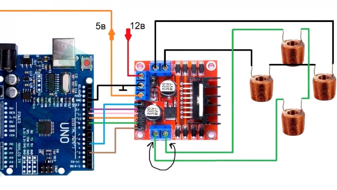
Well, figured out the theory, let's move on to practice. The brain of the circuit will be Arduino Uno.
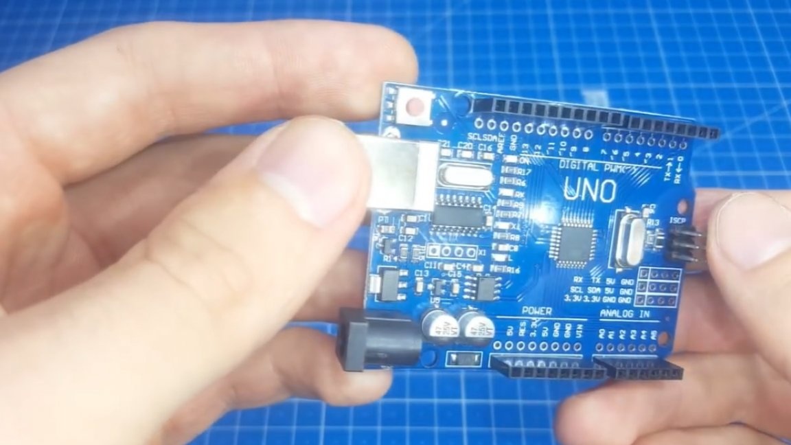
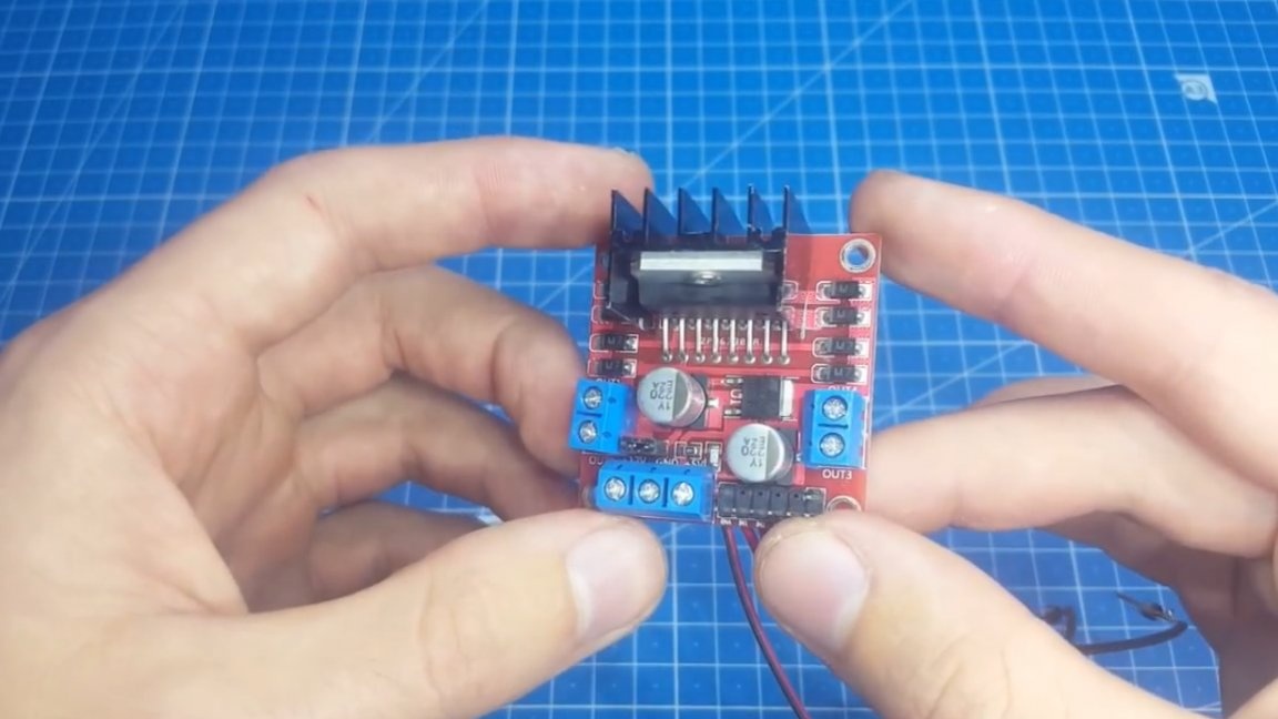
At first, the author wanted to use the Arduino Nano, but inadvertently burned it, giving the wrong voltage. The power part of the circuit is the L298N stepper motor driver.
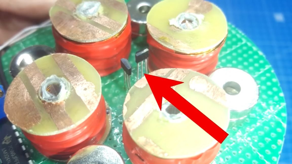
Well, the tracking part is 2 Hall sensors located in the center of the structure.
Now let's consider the device diagram, let's start with the block diagram.
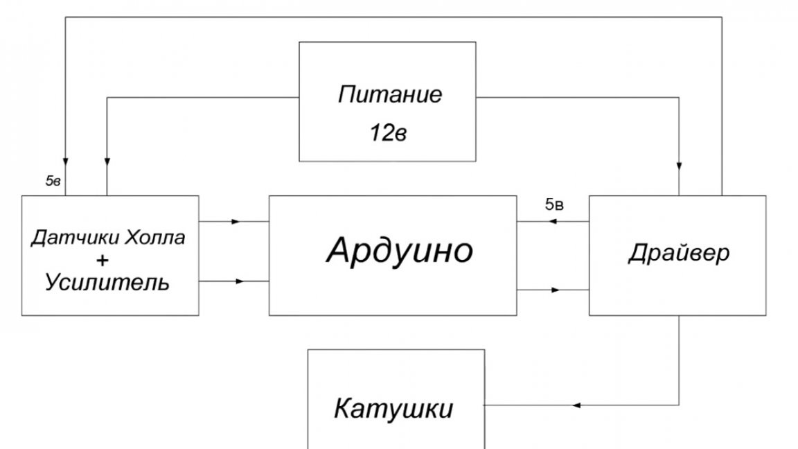
The diagram shows what is connected to, now we will consider each block separately. The Hall sensors are equipped with an additional amplifier on the LM324 chip. The amplified signal from the Halls is fed to the analog input of Arduinki.
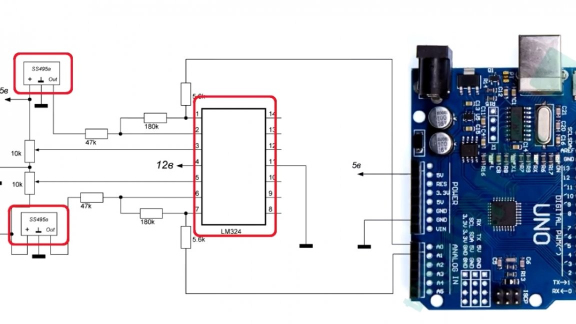
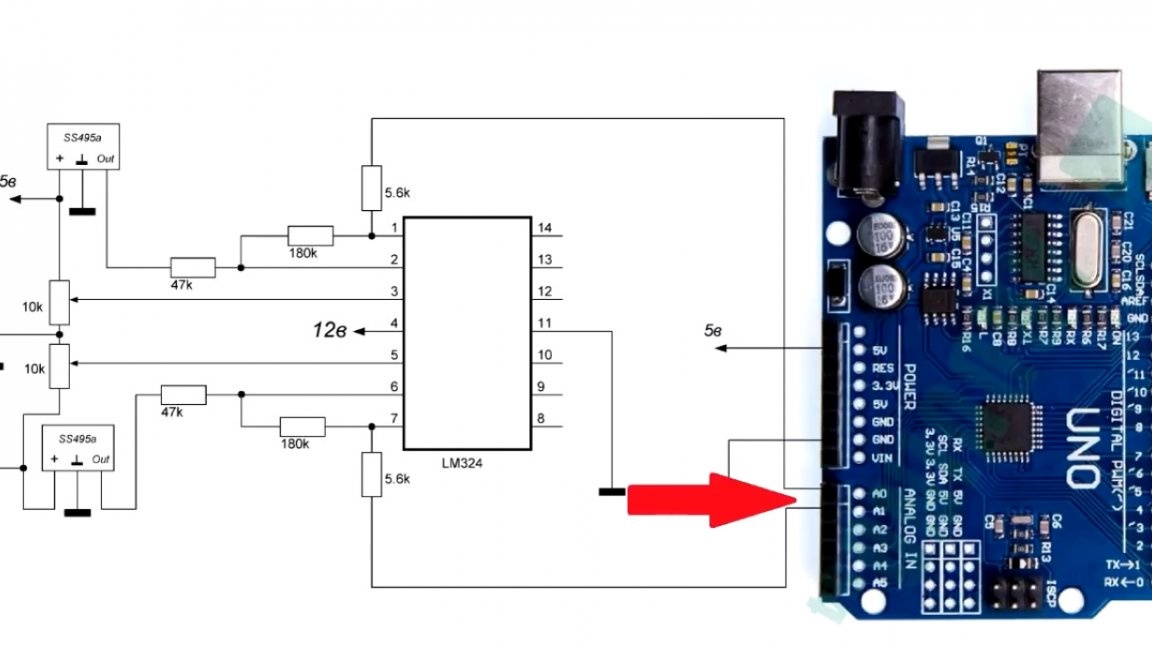
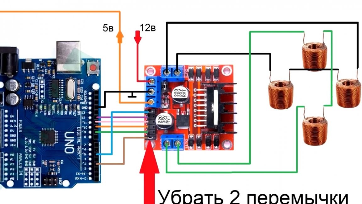
Next block - This is the driver and coils. About their winding a little later, but now it's a pure scheme.
As you can see, everything is connected elementary and without any problems.
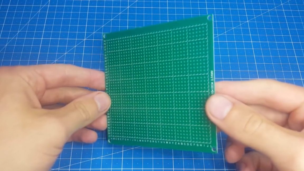
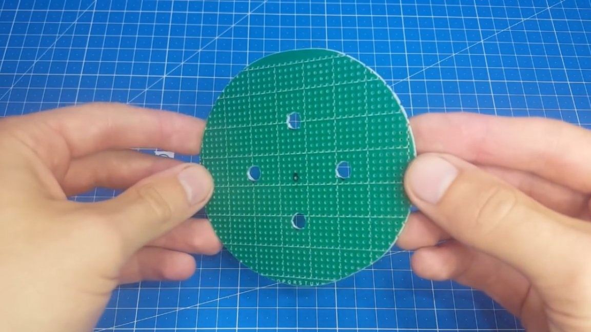
Now go to the assembly. As the basis we will use a breadboard. It needs to be slightly reduced and holes drilled. The distance between the holes is 40mm.
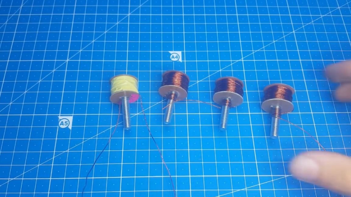
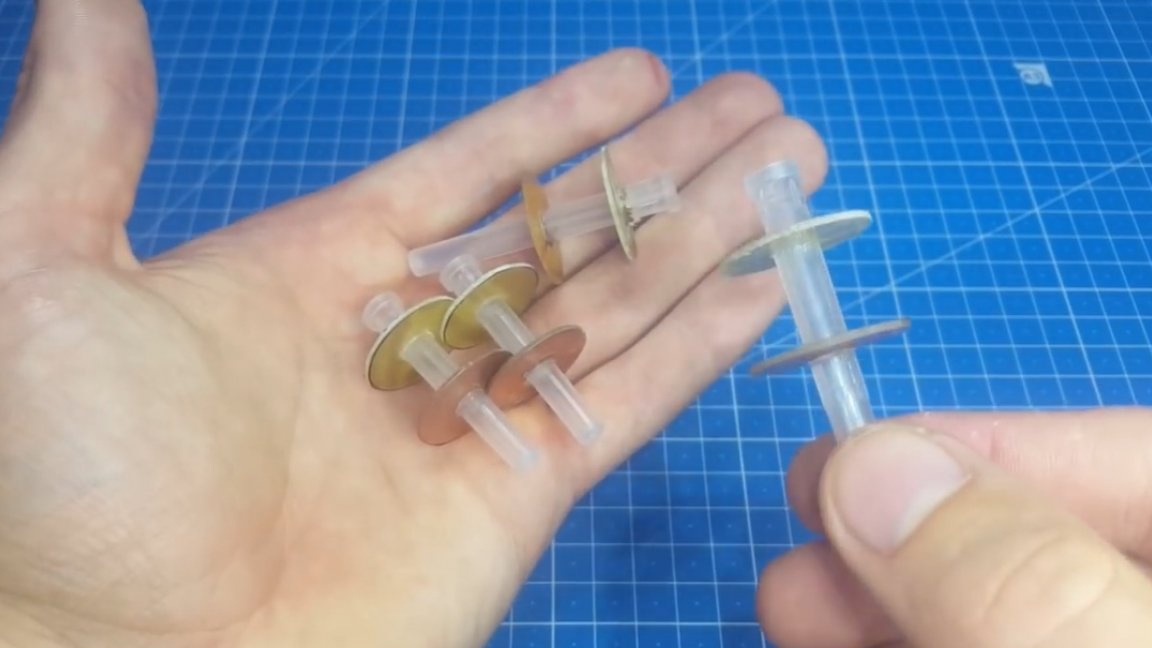
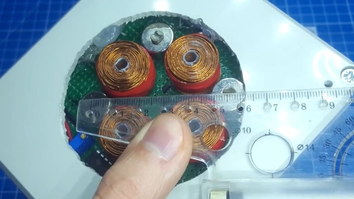
After preparing the breadboard model, we will engage in winding coils. As mentioned earlier, it was in the coils that was the problem, since they were all with a metal core. As a base, take a cap for a syringe needle. The limiters for the coils themselves are made, as in the first versions, of textolite.
The size of the coils in front of you.
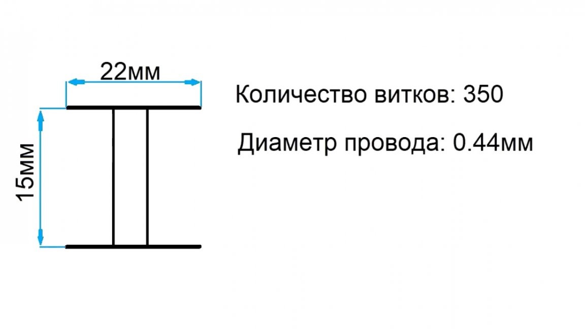
All of them are wound in one direction. The number of turns 350, the diameter of the wire 0.44 mm. I think if you make 10 or even 20 percent changes in the parameters of the windings, the result will not change.
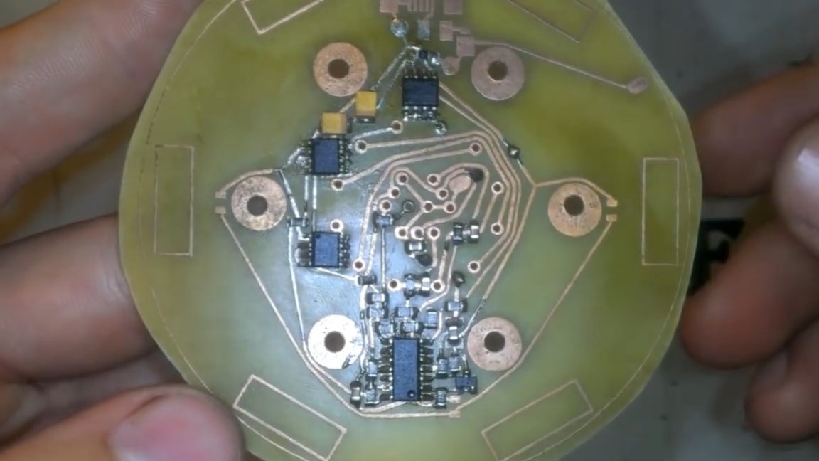
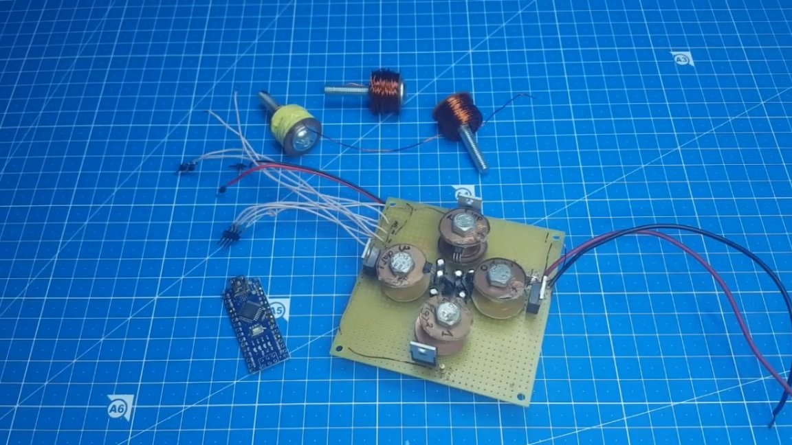
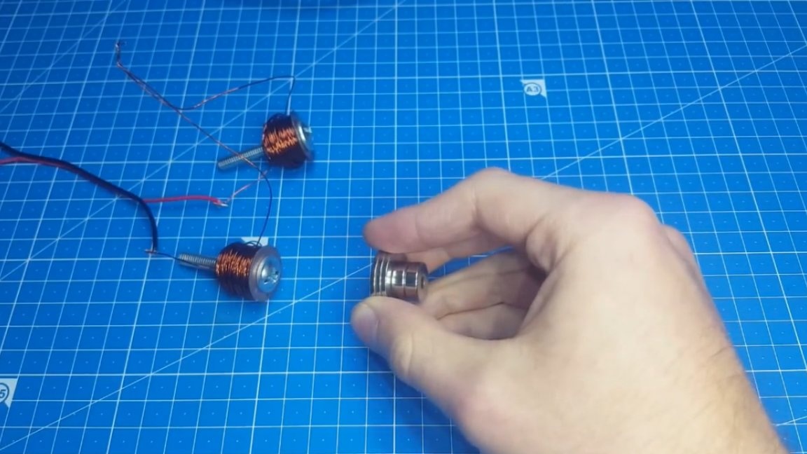
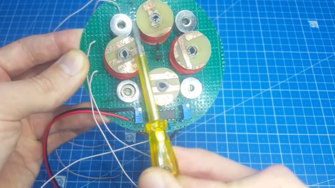
When the coils are ready, install them on the board, like the rest of the parts. Now it is necessary to connect the coils of 2 pieces in series, so that when applying voltage to a pair of coils, one of them attracts, and the second repels at this moment.
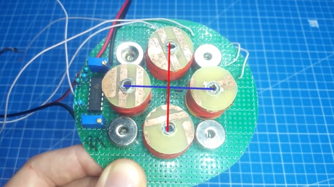
Regarding the location of the Hall sensors. They should be strictly on the axis of their coils. Where they are deployed does not play a role, everything will be adjusted in the settings.
The next step - connection of all elements in one circuit and Arduino firmware. You will find the sketch itself and all the pictures with the schemes in the project archive.

But after the firmware difficulties begin. Permanent magnets cannot be placed in the base for adjustment. When the sketch was uploaded to Arduino, we take the magnet, which should be levitated and placed above the coils, moving our hand over the place where the levitation point should be, we should feel the resistance of the coils.
Suppose we drive to the left, so the coils are triggered and pulled to the right, if the traction goes in the wrong direction, then you need to swap the outputs of the coils on the driver.
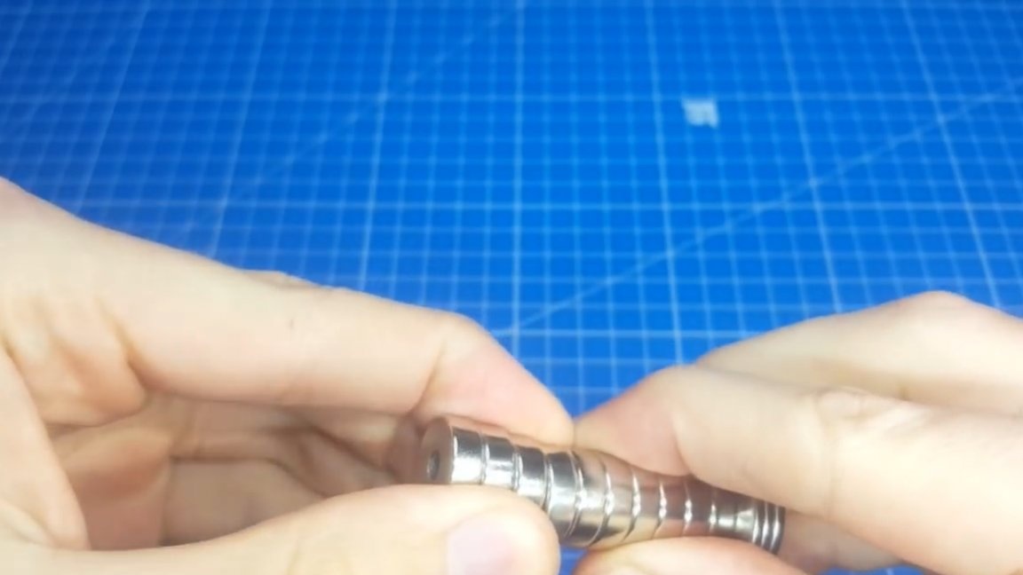
Now it is time to install the magnets on the board. Magnets must be neodymium.
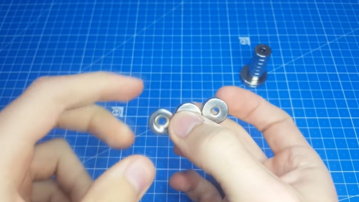
In general, you can use rectangular magnets at the base, but the author decided to take round ones, since they are cheaper and have a hole for mounting. We install magnets in the spaces between the coils. The diagonal distance between them is 5.5 cm.
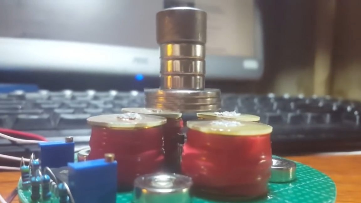
Now we take a magnet, which we will suspend and try to place it in the center of levitation. It is important to guess with the weight of the magnet. The author did this, took the main magnet and hung small ones on it, thus finding a balance. But the magnet in the center did not hang for long, it was constantly being demolished in one direction. Here tuning resistors come to our aid, rotating them you can shift the equilibrium point. Thus we align the soaring magnet.

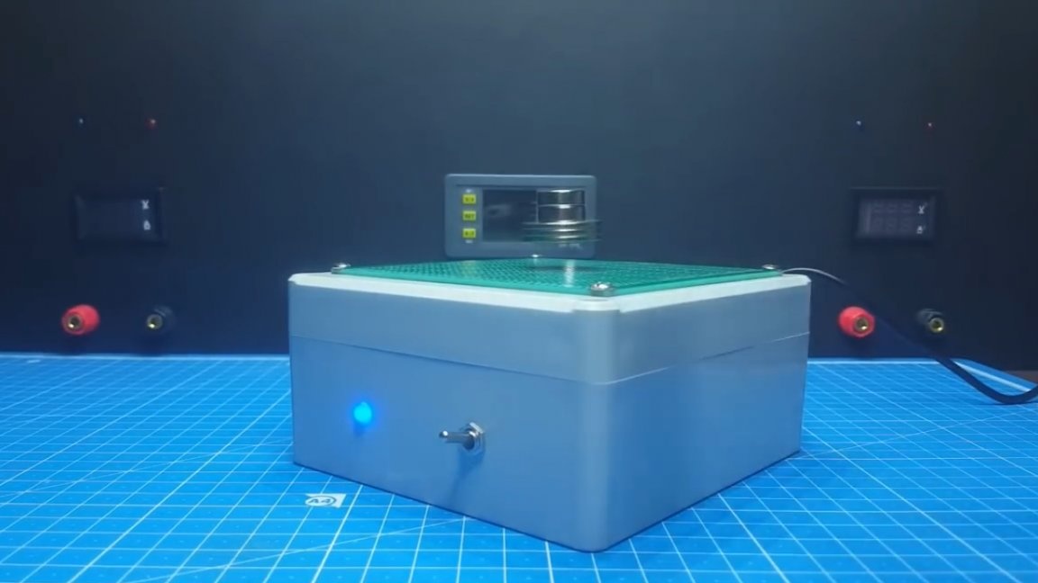
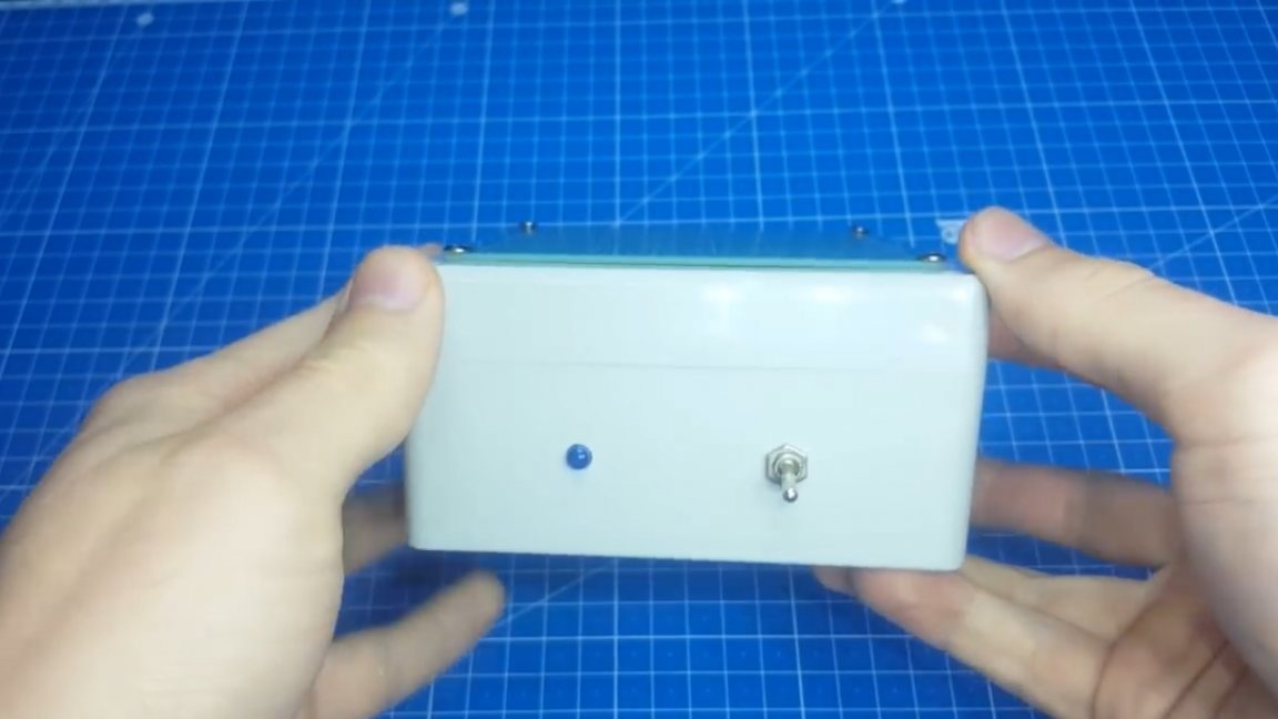
Everything, setup is completed. It remains to arrange all this beautifully in the case. Such a box is suitable for this.
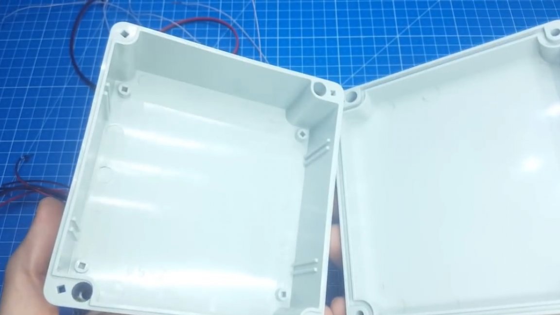
But, as it turned out, it has very thick walls, and we have every millimeter literally worth its weight in gold. Therefore, it is necessary to cut a hole for the coils in the lid and fix them flush with the housing.
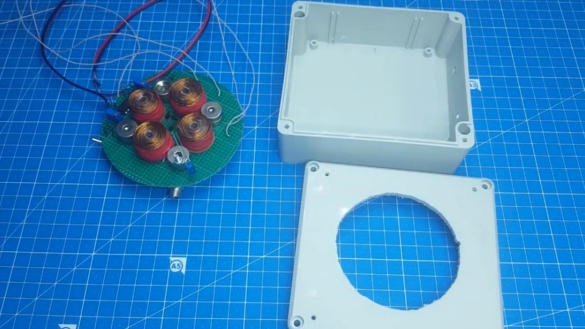
The resulting hole in the case had to be covered with something. And here another prototype board came up perfectly, it turned out very well.
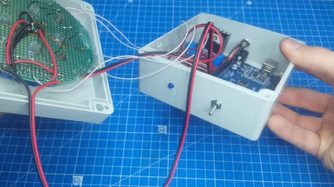
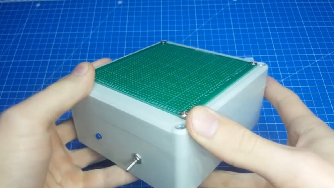
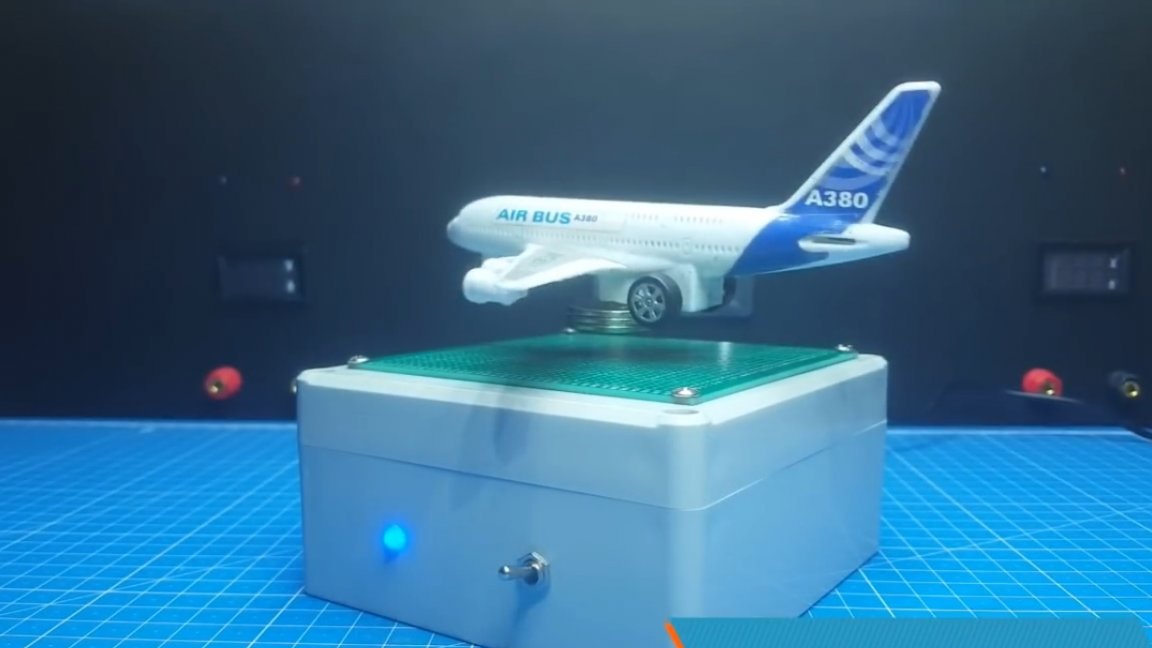
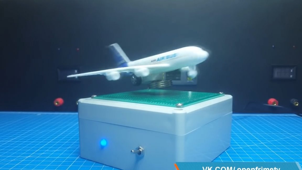
The driver and Arduinka are located in the case, and we take the power from an external adapter for 12V, 2A. As a result, the design became similar to the factory model. On it, you can install some kind of decorative thing such as an airplane or a typewriter, and enjoy.
That's all. Thank you for attention. See you soon!
Video: