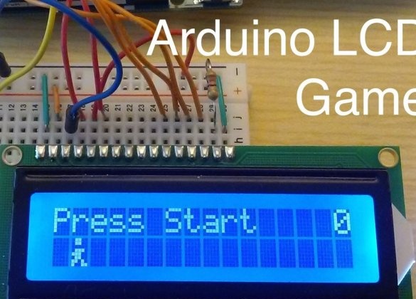
The author of Instructables under the nickname joshua.brooks invented a platform game on Arduino with one-button control. All you have to do in it is bounce on time. It turned out - the score increases by one, it didn’t work out - the game stops, and a new one can be launched with the same button that is used for jumping.
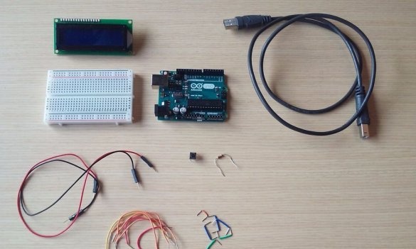
The game program runs on Arduino Uno, to which a two-line display on the HD44780 chip is connected. The button, when pressed, connects Arduino pin 2 to a common wire. It is good to tighten the connection point of this button with the Arduino upwards with a 10 kOhm resistor, thus improving the noise immunity. The display backlight is powered through a 220 ohm resistor. All this, along with a breadboard-type breadboard, cable and jumpers, is shown in the photo:
Before assembly homemade the master makes sure that the display has a standard wiring:
1 - GND - common wire
2 - VCC - plus power
3 - V0 - contrast setting
4 - RS - register selection
5 - R / W - read / write
6 - E - resolution of the operation
7 - DB0 - data bit 0 (not used here)
8 - DB1 - data bit 1 (not used here)
9 - DB2 - data bit 2 (not involved here)
10 - DB3 - data bit 3 (not used here)
11 - DB4 - data bit 4
12 - DB5 - data bit 5
13 - DB6 - data bit 6
14 - DB7 - data bit 7
15 - LED + - plus backlight
16 - LED- - minus the backlight
On some displays, especially on the KB1013VG6 chip, but not only, the pinout may vary. It’s okay to look into the datasheet and adjust the circuit - a momentary matter. And everything will work.
The first four bits are not used because the Arduino sends data to the display in four-bit mode. Before that, he uses the same conclusions to configure the display accordingly.
During the build of joshua.brooks, power is not supplied to the circuit. It connects the positive and general conclusions of the Arduino (5V and GND, respectively) with the corresponding buses of the packet board. He does the same with the display, there it is necessary to connect pin 2 to the plus bus, and to the common one - 1 and 16. He does not connect terminal 15 of the display (backlight power) directly to the plus bus, but through a 220-ohm resistor.
Then he takes on the connection of the Arduino with the display:
Connects DB7 display input to Arduino pin 3.
Connects DB6 input to Arduino pin 4.
Connects DB5 input to Arduino pin 5.
Connects the DB4 input of the display to pin 6 of the Arduino.
Connects input E of the display to pin 9 of the Arduino.
Connects the R / W input of the display to pin 10 of the Arduino (or common wire)
Connects the RS input of the display to pin 11 of the Arduino.
Connects V0 input to Arduino pin 12 (or common wire).
If desired, you can add a contrast adjuster. Now he is always at maximum.
The button remains. The wizard connects one of the pins of the button to a common wire, the other to pin 2 of the Arduino. It is better to add a pull-up resistor (see above). Everything is ready for programming.
The entire development cycle of joshua.brooks was spent at Tinkercad. , with some lags, you can play this game in a virtual machine, modify the code and immediately see what happens. There is also a Download Gerber button for those who want to assemble the game on a printed circuit board. And if your Tinkercad lags very hard, immediately download and try to run it on a real piece of hardware.
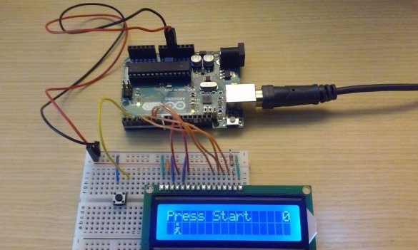
You should get something like this:
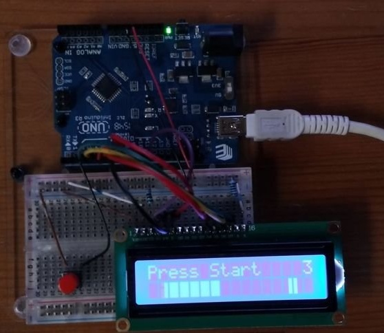
Although this game did not even take third places in any competitions that Instructables really like, it became a real hit there. Its repetition was reported by 23 users. For example, kb55mail:
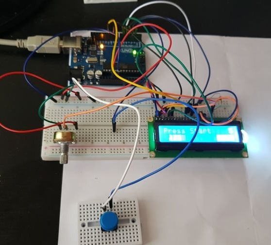
Rob Cai:
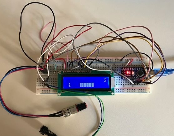
aryas25:
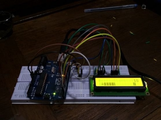
zhollett:

Other. And you?

