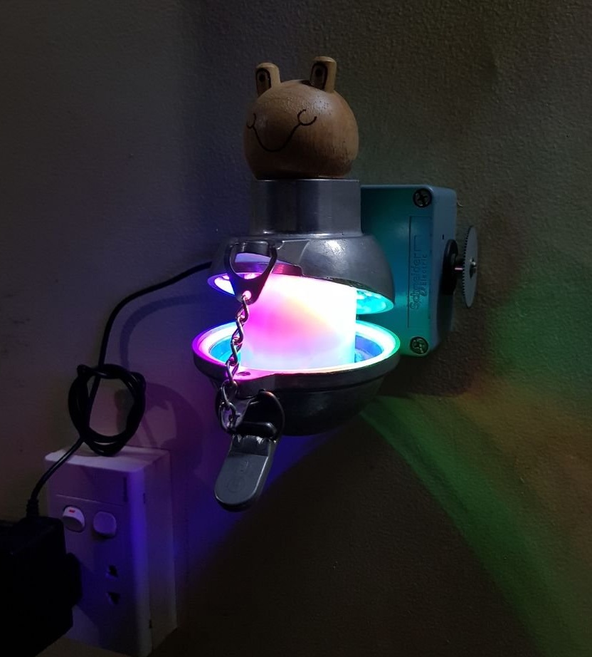
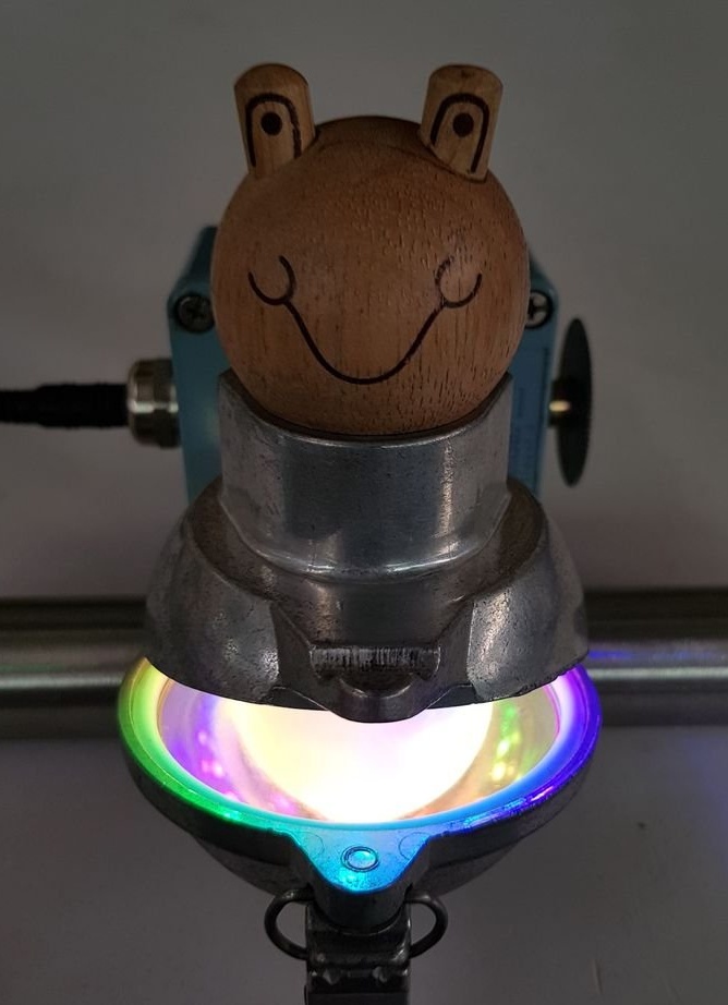
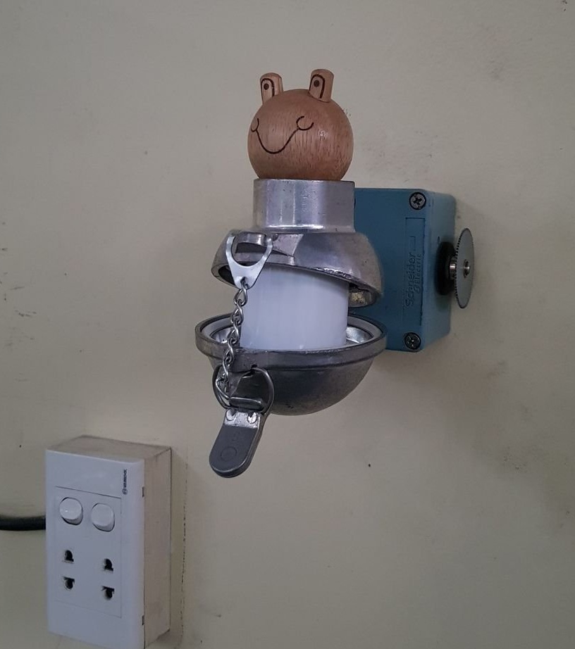
The original lamp made by Instructables under the nickname tuenhidiy can be opened and it will light up from the inside. The color of the glow is adjusted using a variable resistor and a button.
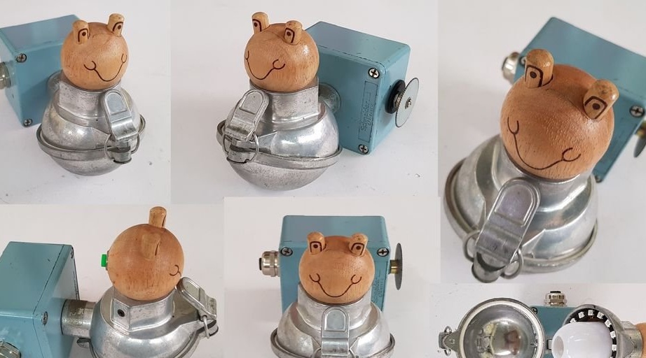
The luminaire design includes: a spherical casing from an industrial thermocouple, a casing from a push-button post, a cable gland ... Look, what a beautiful casing:
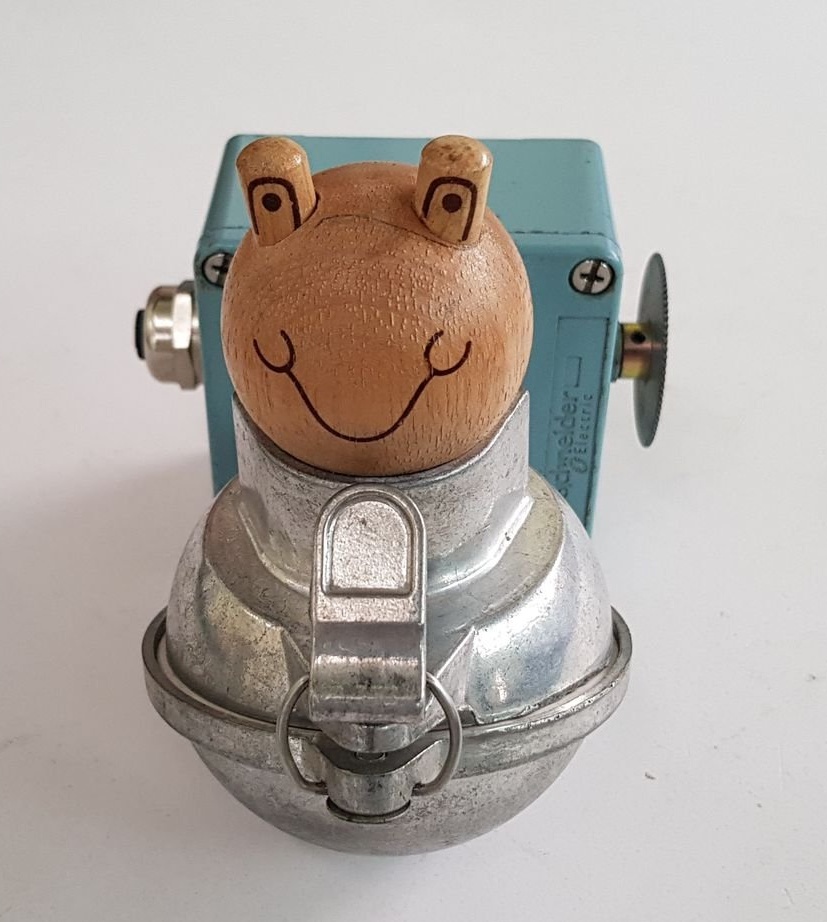
The case of the button post is from Schneider, type XAPM1501H29. It is made of zinc alloy. You can, of course, use something simpler as well, the result will be no worse. For beauty, a 20 mm polyamide or nickel cable gland is attached to the body, it is installed in an existing hole.
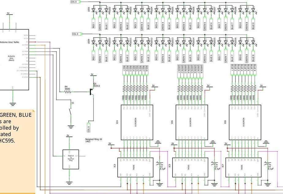
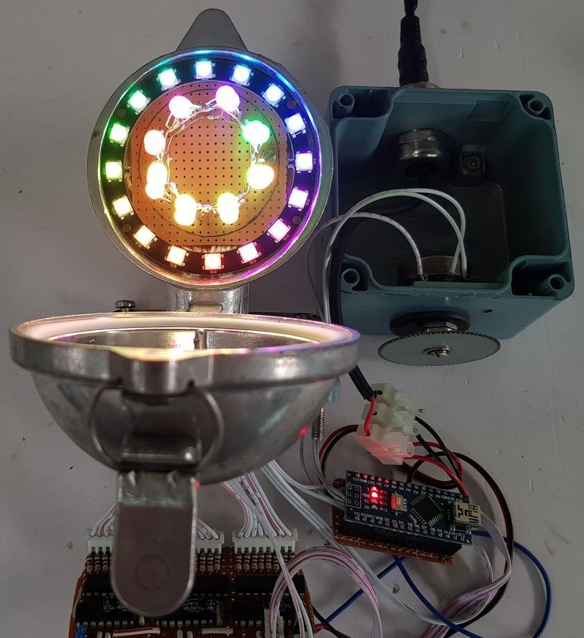
Governs everything board Arduino Nano. There are two types of light sources: the Neopixel Ring 16 module and 16 RGB LEDs with a common anode. Six microcircuits are still needed: three shift registers 74HC595 and three sets of composite transistors ULN2803. Well, the little things: three capacitors at 0.1 μF, 24 resistors at 100 Ohms, one transistor A1013 and one power socket. The board uses a breadboard type perfboard, the device is powered by a five-volt power supply.
The scheme at first seems complicated, but if you look at it, everything becomes clear:
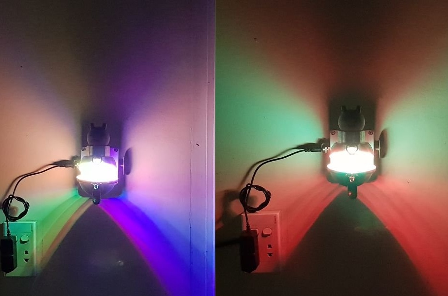
The button switches the modes, a variable resistor allows you to choose the colors of the glow of both the LED ring and discrete RGB LEDs.
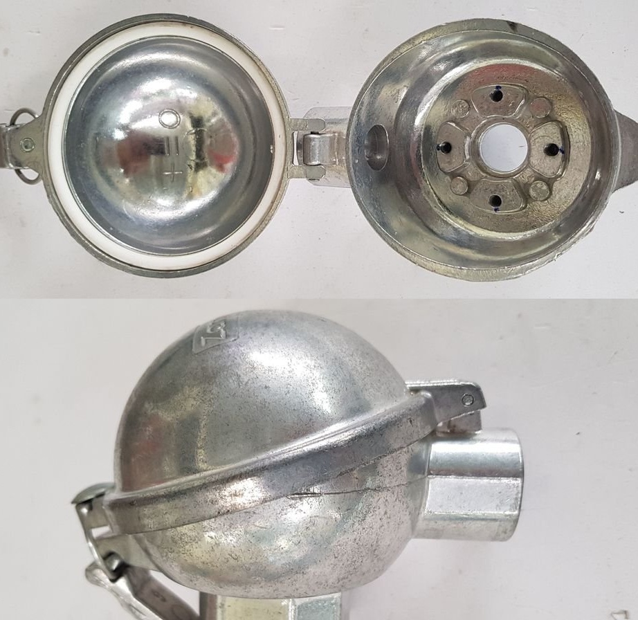
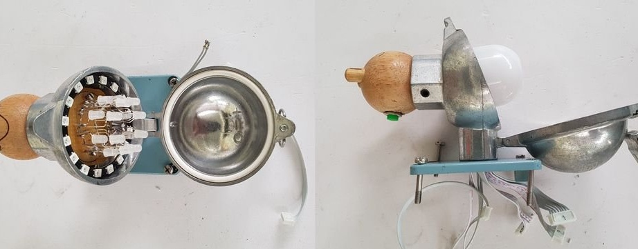
The master takes the casing from the thermocouple:
There are two holes in it, one with a diameter of 21 mm, the other in 32. The first tuenhidiy uses to connect the casing to the body of the button post, the second - with the “snowman's head” on which the button is located.
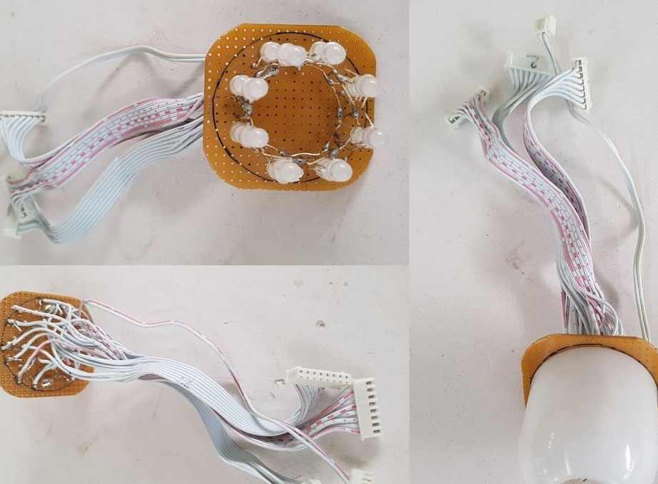
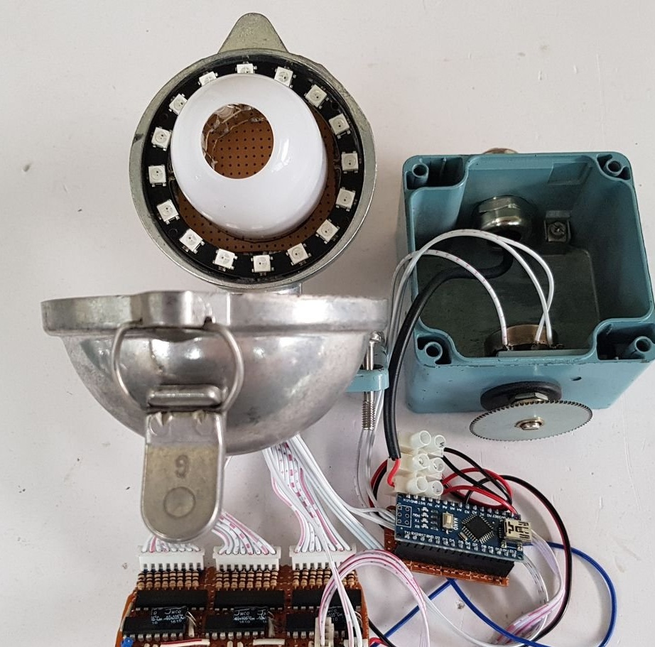
On a piece of a perfboard-type breadboard, the master assembles a two-story structure of RGB LEDs by combining their anodes. The wires from all cathodes and the connection points of the anodes are output to the connectors. Installs the diffuser:
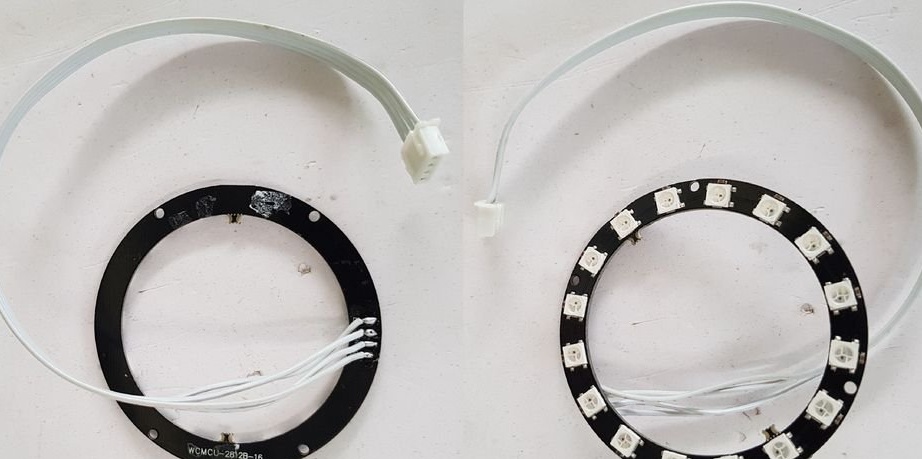
Solder the cable with the connector to the NeoPixel Ring 16 module:
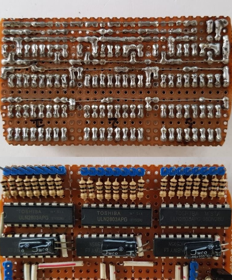
Assembles a shift register board according to the scheme:
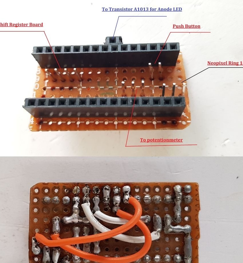
Arduino outputs connected to the register board are configured as follows: resolution - 3, latch - 2, clocking - 13, data - 11.
Then the wizard on another piece of the breadboard builds the adapter for the Arduino Nano:
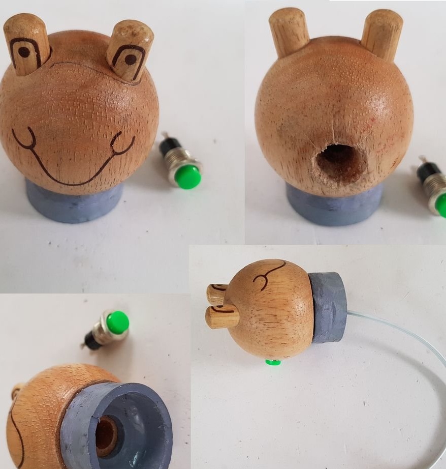
He makes the head of what he calls a snowman, with a neck from a piece of PVC pipe, puts a button inside and displays a cable from it:
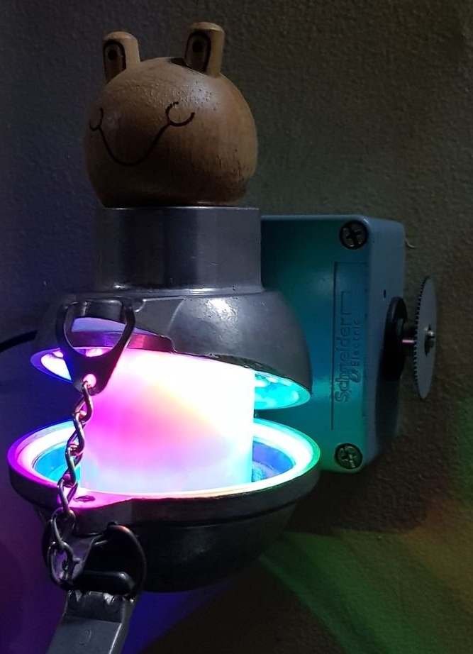
It combines the head of a snowman, the casing from the thermocouple and the cover of the button post:
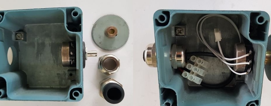
Installs a variable resistor with a control handle, an oil seal and a terminal strip in the button post housing:
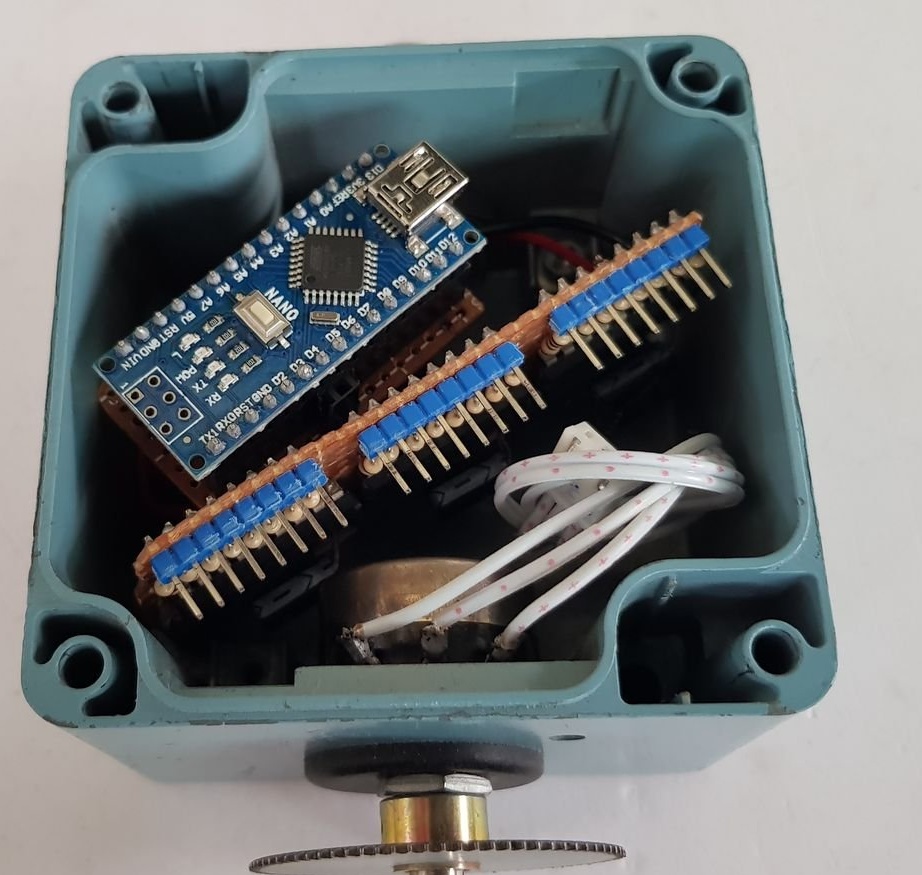
Trying on how to fit the Arduino Nano and the shift register board:
Everything connects, how isolates the boards from the metal case - it is not clear: