
This article is about people whose second home is garage and which rummage in electronics. In general, for the garage, you can make 100,500 useful electronic devices. But today, the author (AKA KASYAN) offers to consider 3 schemes of medium complexity, which can be used for a variety of purposes and will be very useful not only for the garage.
So let's get started.

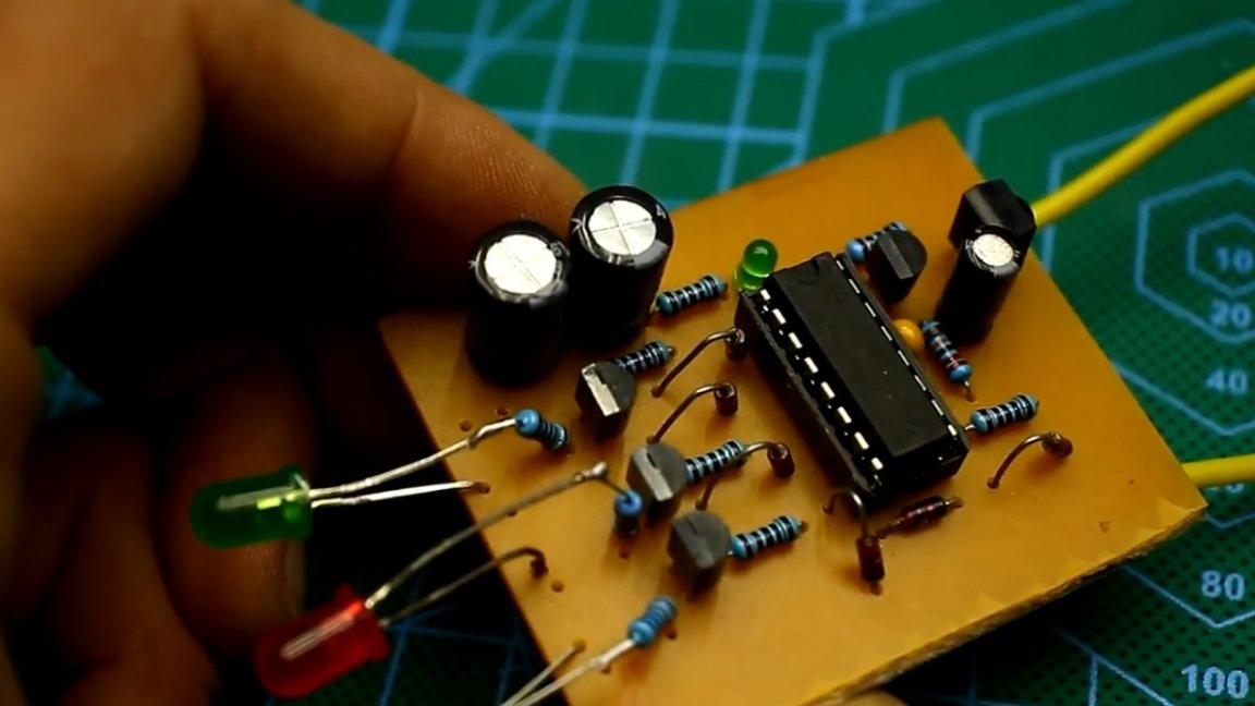
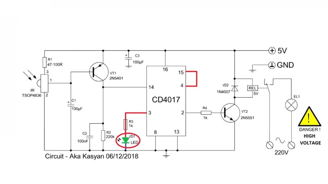
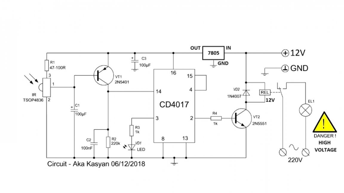
A simple remote control switch can be made on the basis of the decimal counter of the cd4017 decoder.
Such a switch is controlled from any infrared remote control, for example, from a TV, DVD player, and so on.
The scheme has been circulating on foreign sites since 2011.
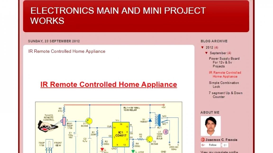
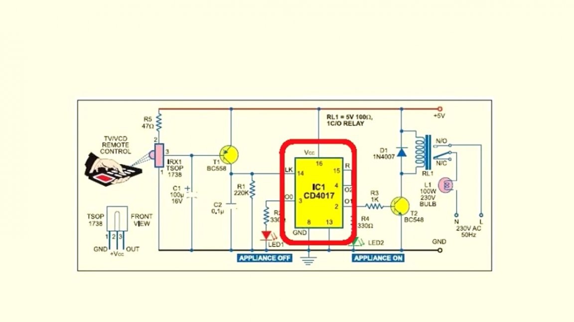
Unfortunately, the source could not be found, but one thing is clear - the version of such a switch is quite popular and is found on almost every site. The counter has 10 outputs.
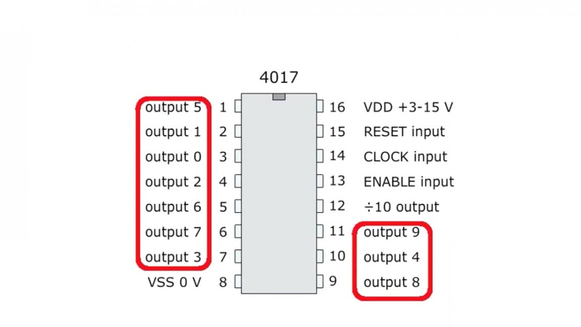
After supplying power at the first output of the microcircuit (and this is our contact number 3), we have a high-level signal or a logical unit.
According to the circuit, an LED is connected to this contact, which will light up as soon as we apply power to the circuit.
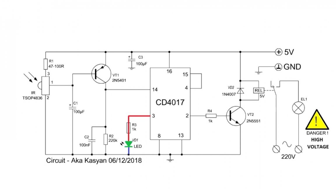
The infrared signal from the remote control is received by the receiver. As a rule, at the output of such a receiver, a logical unit or a high-level signal if an infrared signal is not amenable to it, and a logical zero if a signal is received at the receiver. In this case, the author calls the signal infrared radiation from the control panel.
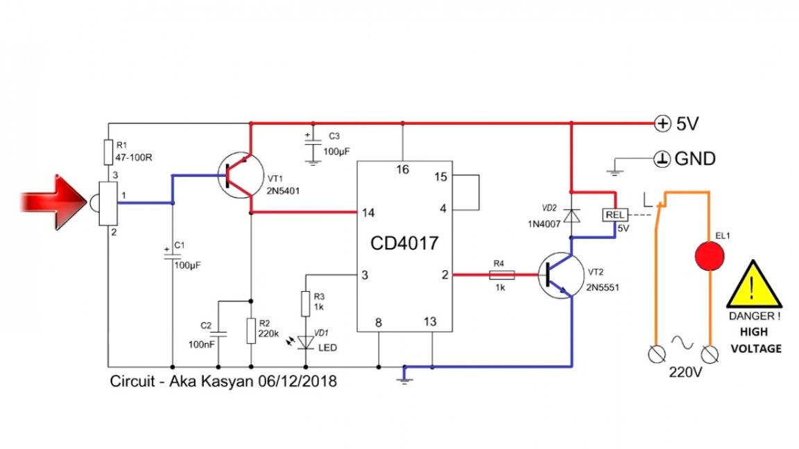
The output of the receiver is connected to the base of the bipolar transistor direct conductivity. In the absence of an infrared signal, the transistor is closed; if there is a signal, it trips. Through its open transition, the plus (+) from the power source enters the counter input, and the unit switches to the 2nd output or output No. 2.
In this case, the 2nd transistor will trip. Through its open transition, power will be supplied to the relay winding and the latter will operate by switching the load.
When you press any button on the remote control again, the unit will switch to the 3rd output or output 4. The transistor will close, the load will turn off. The fourth pin of the chip is in turn connected to the counter reset pin. Thus, the countdown will start again and the corresponding LED will light up.
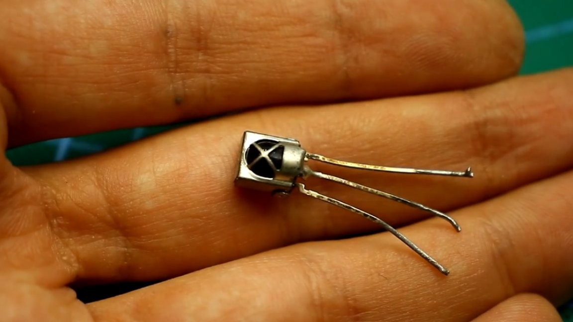
About the infrared receiver. The location of their findings may vary, so the author advises finding a datasheet and studying.The receiver can be taken from non-working household appliances with infrared control.
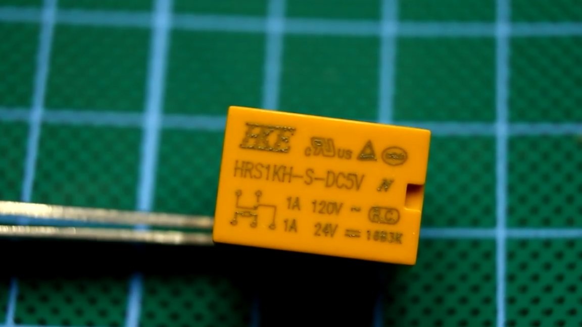
The relay is selected with a 5V coil voltage.
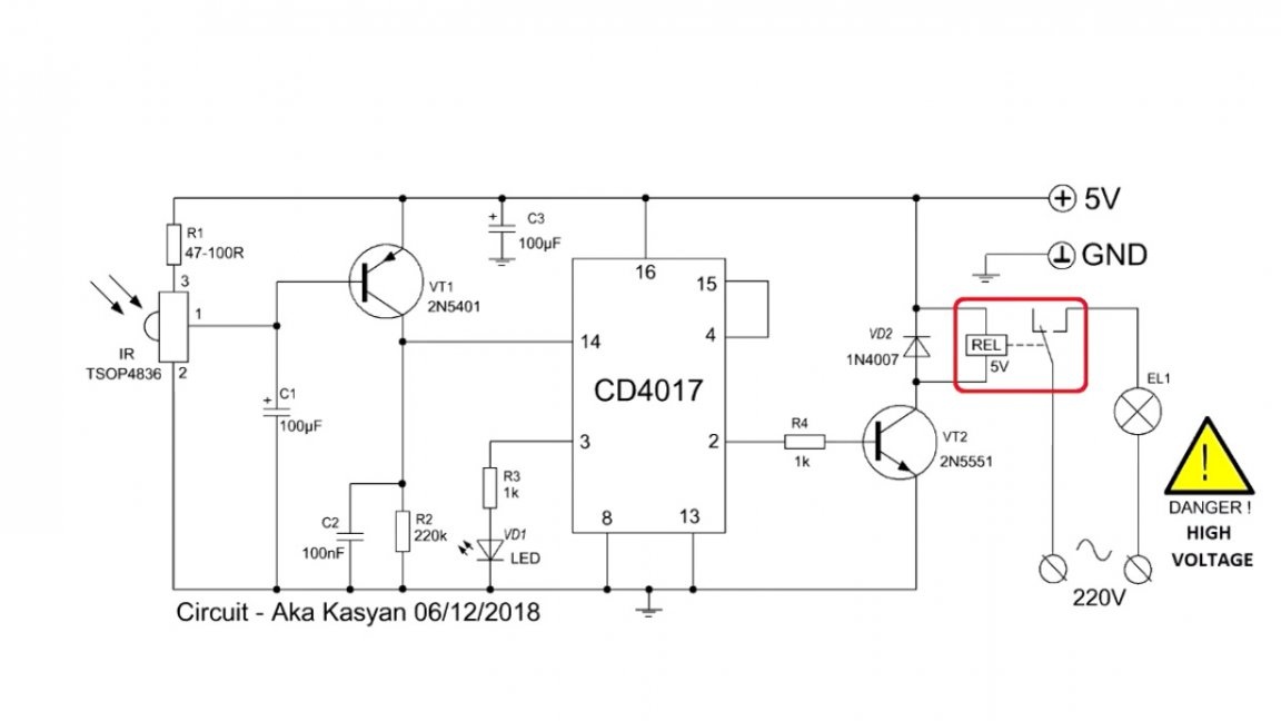
You can also use 12-volt relays, in this case, the control circuit must be powered from a step-down stabilizer by 5-6V, and apply 12V to the input of the circuit.
Second circuit was developed by the author on the basis of the first option. This switch can control 3 different loads, in fact it is already a switch, we have 4 operating modes.
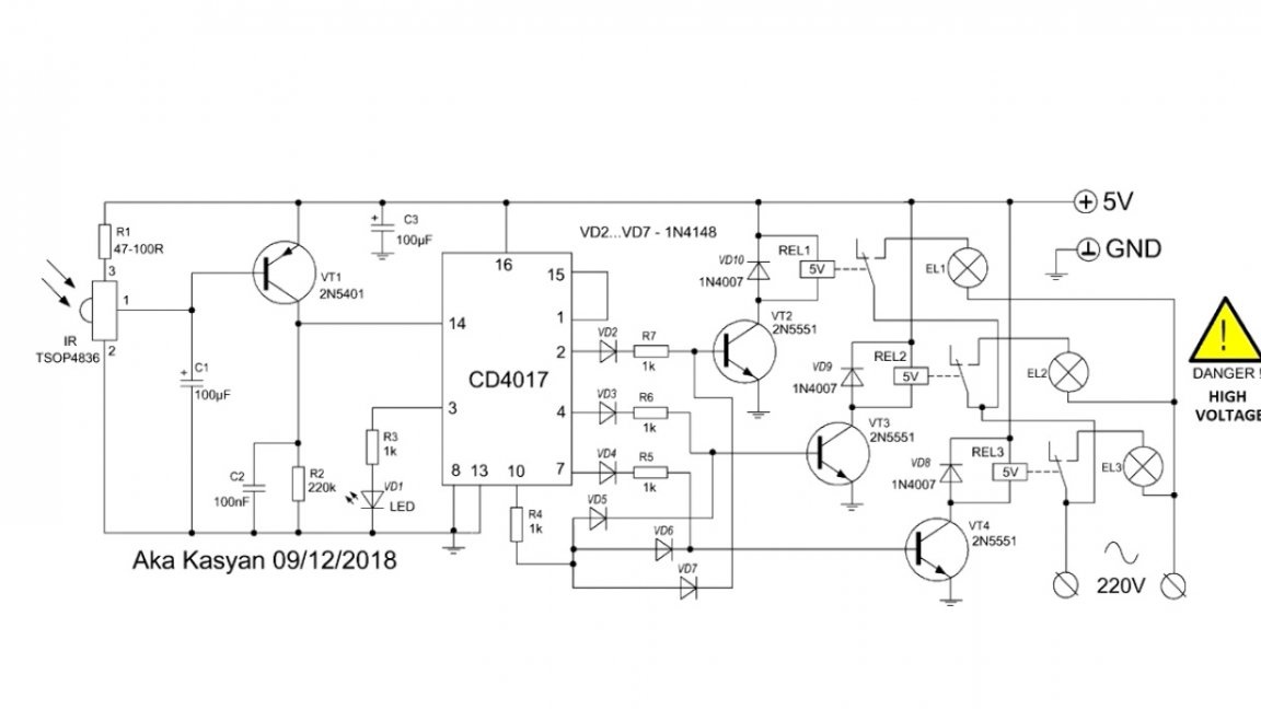
First press - on pin 2, a unit appears and a high-level signal opens the first transistor. The first relay trips, switching the load, for example, a light bulb.
The second press - the unit from the 2nd output switches to the 4th. The first relay is turned off and the second is activated, activating the second lamp.
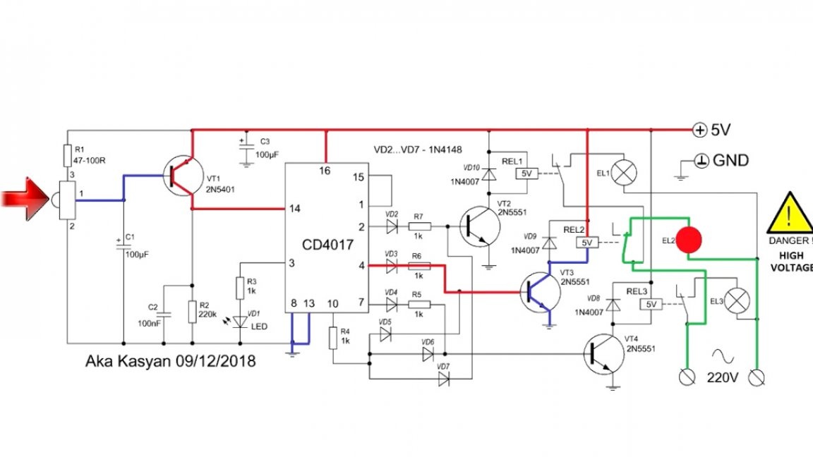
The same thing happens the next time the 3rd relay is triggered.
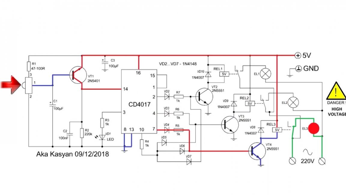
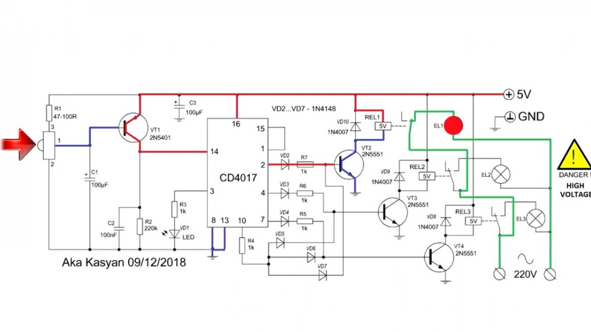
Fourth press - a unit appears on pin 10 and through diode isolation this unit enters the bases of all 3 transistors, which leads to the simultaneous operation of all 3 relays and, accordingly, all the lamps are lit.
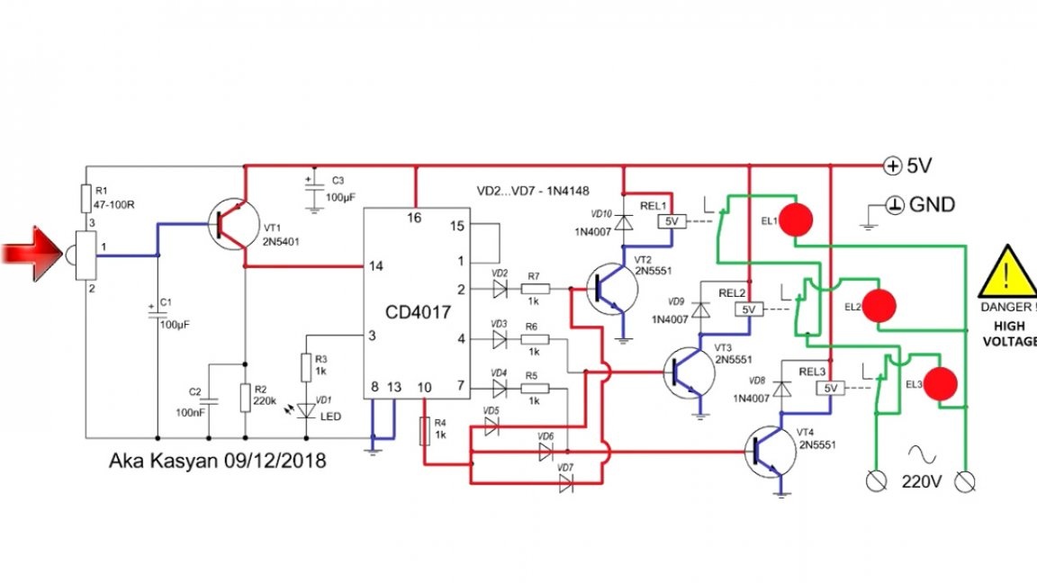
Subsequent pressing of the button leads to disconnection of all loads, since the next output is connected to the counter reset pin and the countdown starts from zero, that is, the unit appears on pin 3 and the cycle repeats.
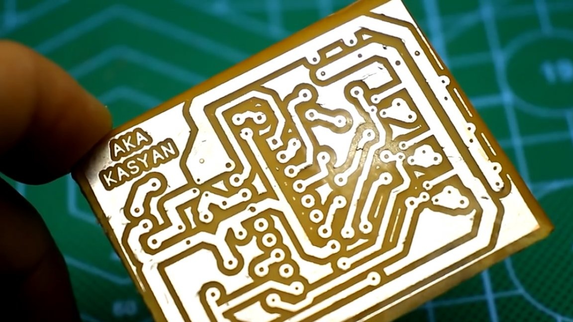
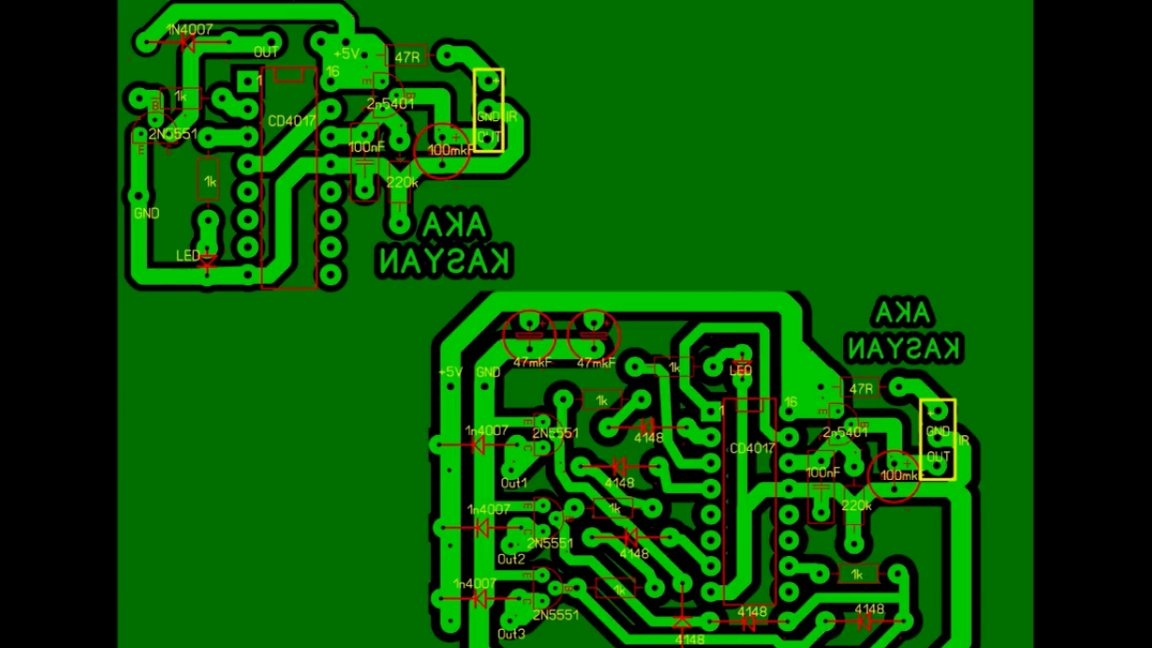
In this embodiment, 5-volt relys were also used. They can be replaced with 12-volt exactly the same way as in the case of the first circuit. Printed circuit boards, as always, together with the general project archive.
The second option is more functional, it is convenient to use it in large garages, in which there are several light sources. Such a switch will allow you to activate lighting in the section of the garage where you work.
Naturally, the switch can be used to activate various loads, electric heating, lighting and so on, it all depends on your imagination. The circuit can be controlled from almost any remote control at a distance of up to 10m. The power of the connected load depends solely on the bandwidth of the relay. Both circuits even work with a 50 percent variation in the ratings of the components used. Transistors are almost any low power corresponding to the conductivity. There should not be a problem with the search for components. The schemes work immediately after power is supplied and do not require additional adjustment, unless of course everything is assembled correctly. Therefore, the author recommends assembling them on printed circuit boards.
Our third scheme protects electrical appliances from power surges.
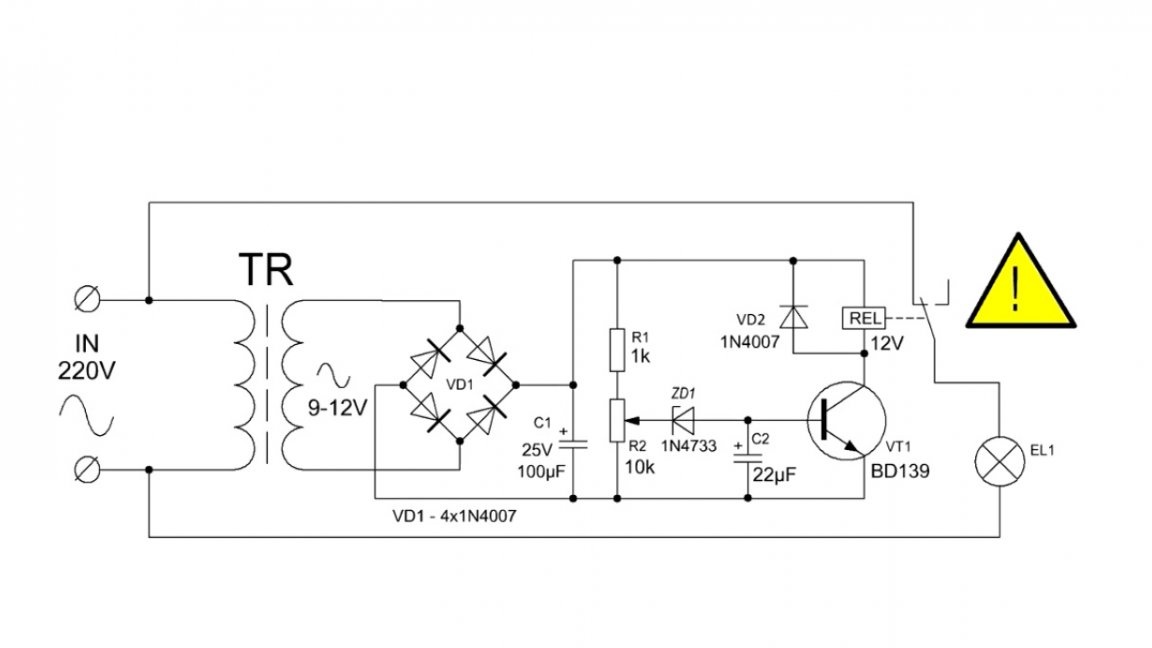
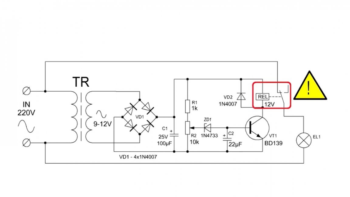
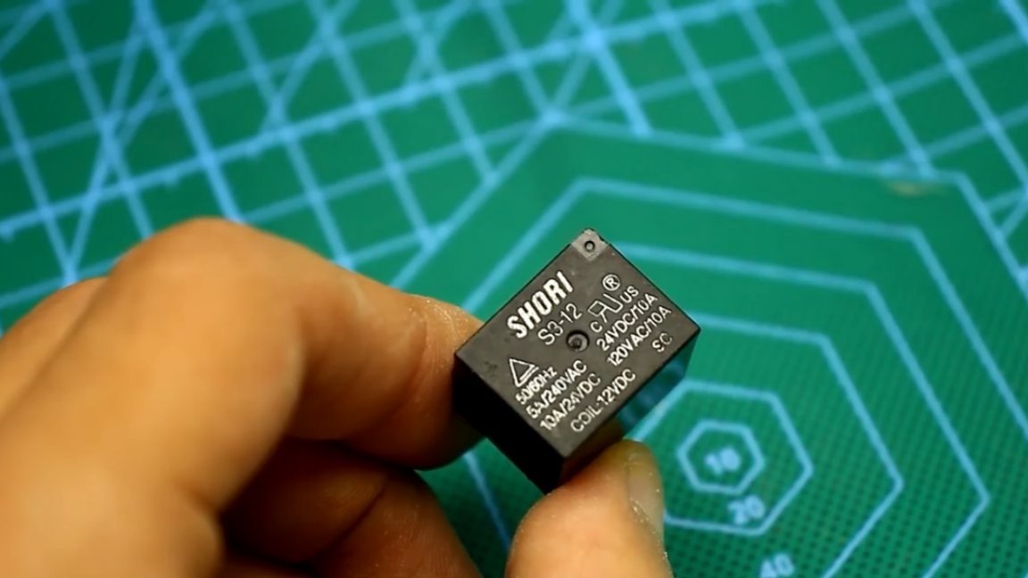
In this circuit we again use an electromagnetic relay, this time a 12-volt one.
In order to galvanically decouple the low-voltage control circuit with the network part, a low-power step-down transformer was used.
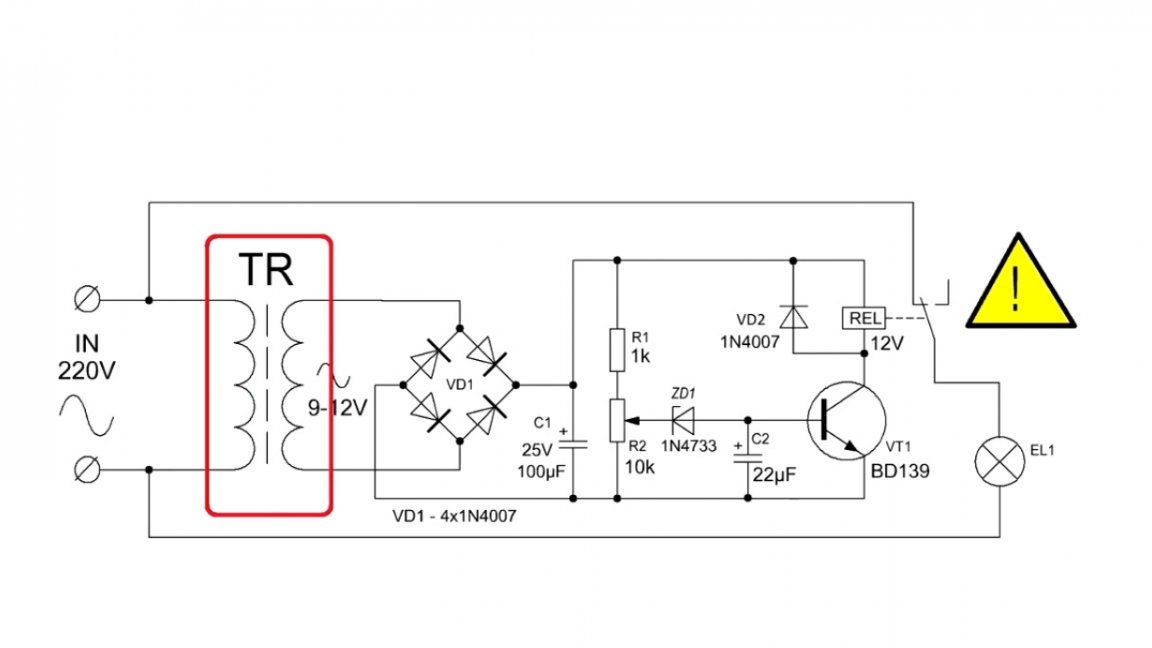
The secondary winding of the transformer should provide a voltage of 9-12V at a current of 150 to 300mA, that is, a transformer is needed with a power of about 2-3W. You can do more, but it makes no sense.
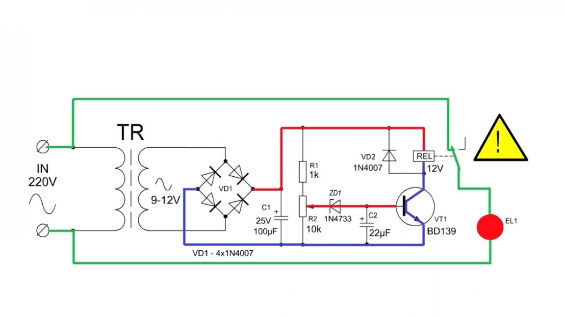
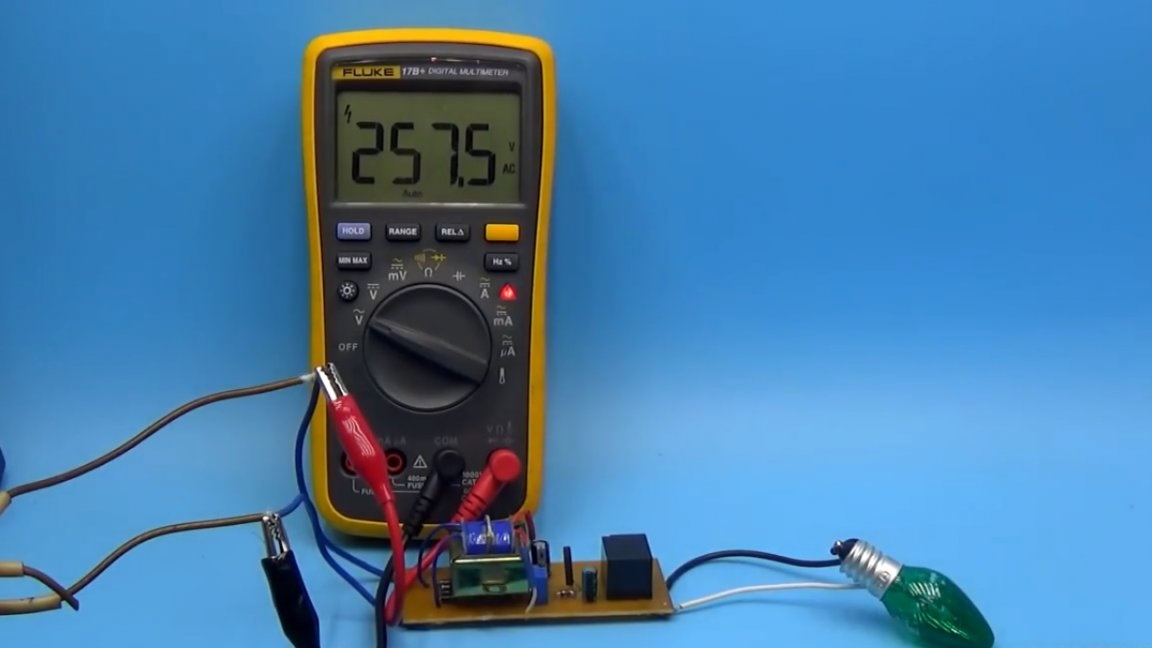
If the mains voltage rises to an unacceptable level, the zener diode is triggered, which leads to the unlocking of the transistor and the relay tripping, and the load that is connected to the network through the protection circuit is instantly disconnected.
Adjust the circuit by rotating the tuning resistor.
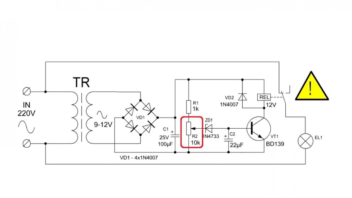
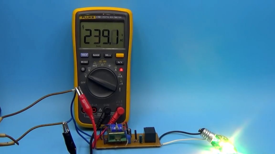
First, we need an adjustable AC voltage source. We apply a voltage of 250V to the protection circuit and rotate the tuning resistor until the relay trips.
This completes the setup. An increase in the mains voltage leads to an increase in the voltage on the secondary winding of our transformer, therefore, the supply voltage of the control circuit also increases. If it is more than the set threshold, the zener diode will work and what will be said at the beginning will happen.
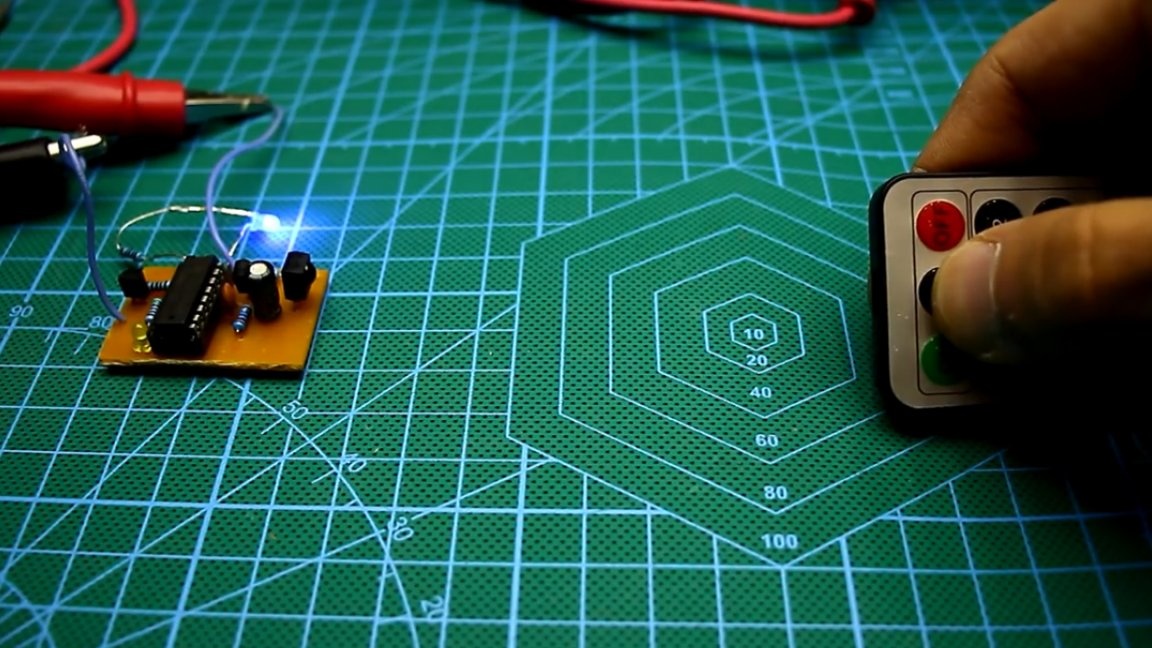
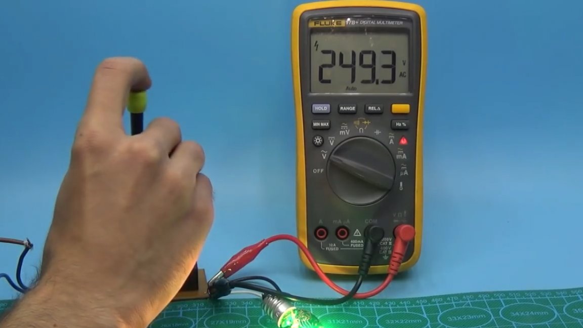
Now it’s time to test our circuit. A small light bulb is connected as a load, the multimeter shows the voltage in the network.
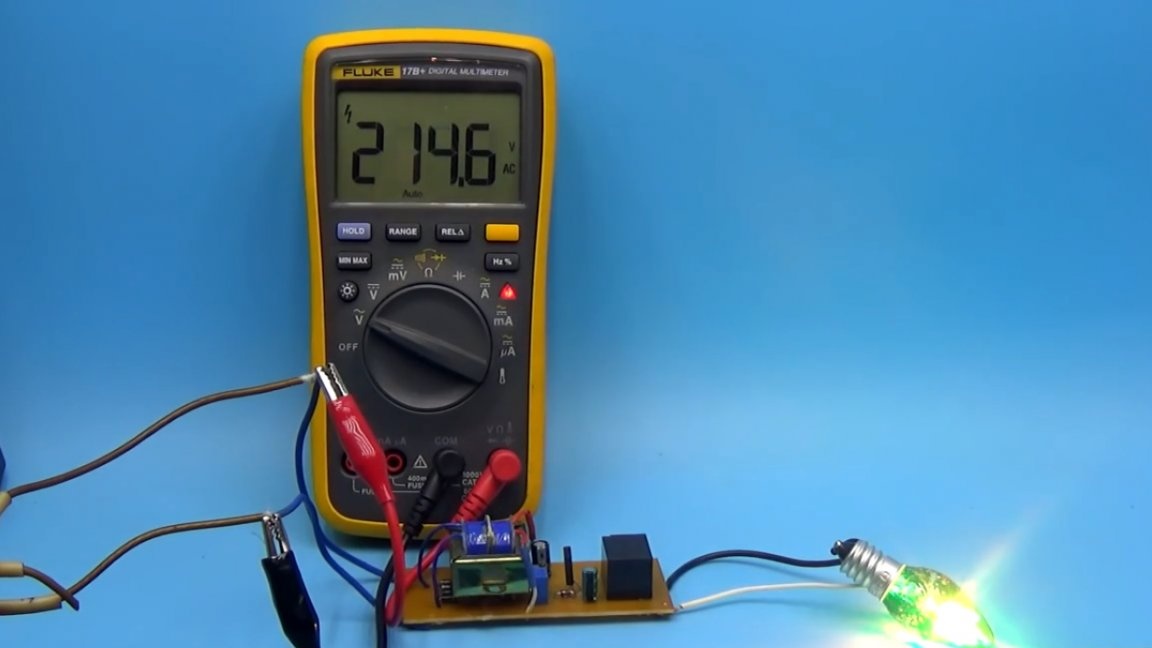
As you can see, everything works.This scheme can be built into an extension cord, or in a separate box and used for health. It should be noted that the power of the connected load depends on the permissible current through the relay contacts. Reinforce tracks on the PCB with solder if you intend to connect high power loads to the circuit.
It is highly recommended that you add a fuse to the circuit.
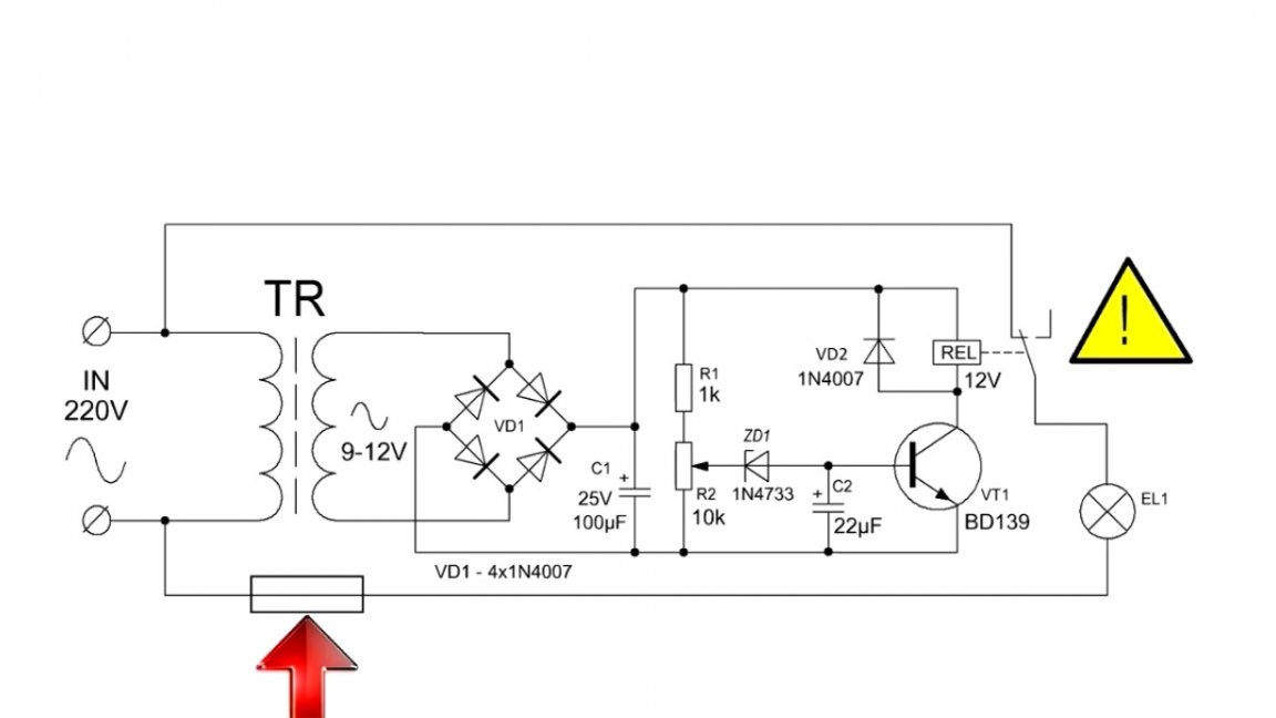
The fuse current is selected according to your load. For example, if you plan to connect loads with a power of up to 1 kW to the circuit, then the fuse must be taken somewhere at 6A. In this case, the relay must be rated for a current of at least 10A. Double current margin is the key to reliable operation of the circuit.
Well, in the end, it is worth recalling that extreme care must be taken when working with mains voltage. During commissioning, disconnect the device from the mains and use rubber gloves.
Thank you for attention. See you soon!
Video: