Of course, it can be built into the player, which in this case simply connects to the amplifier with a cable, as if the pickup in it were piezoelectric. But in more serious audio systems, the phono stage is a separate device with its own body, power supply. The thing is not cheap, so home-made phono stages are not uncommon even for those listeners who prefer ready-made players and amplifiers. These include the author of Instructables under the nickname Zoran.Velinov. He lives in Macedonia, and made the design for a friend producer and DJ under the nickname.
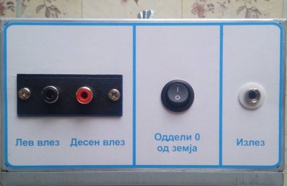
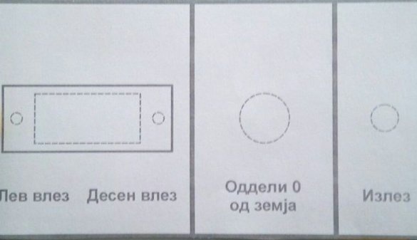
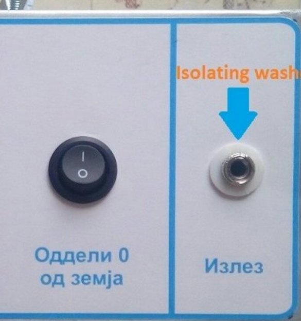
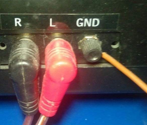
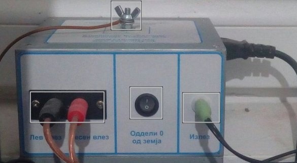
The device is very minimalistic, on its front panel there are two input tulips, a switch for separating the common wire from the ground and a three-pin output jack:
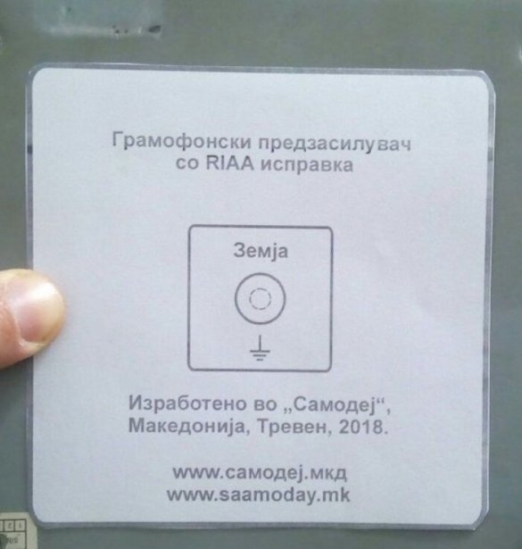
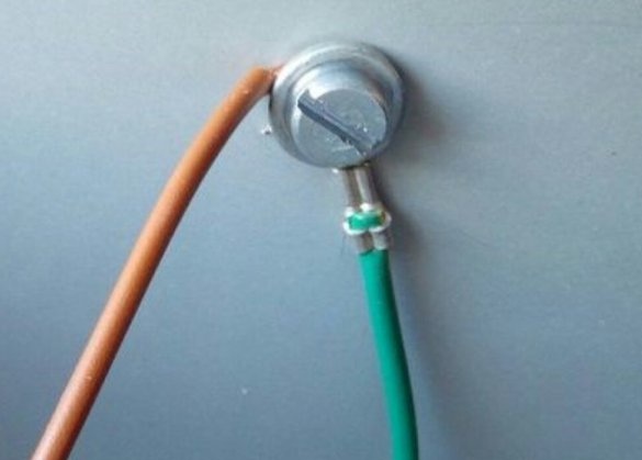
Above is the grounding clamp:
On the side wall (see it later) - connector and power switch.
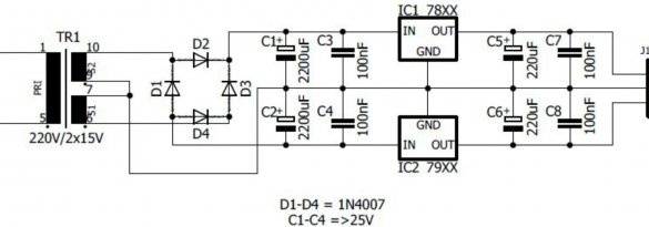
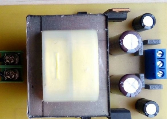
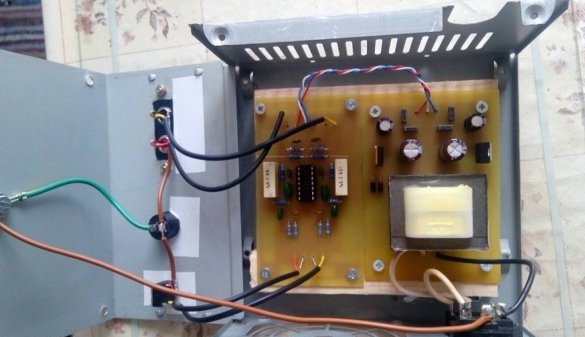
Inside, everything is also quite simple. Bipolar Power Supply:
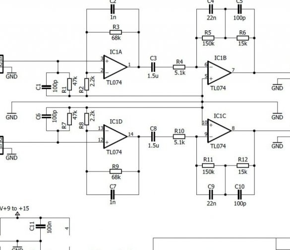
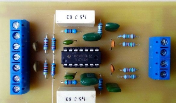
And actually the phono stage:
The power supply unit generates voltages +12 V and -12 V, which falls into the voltage range of the op amp TL074. The stabilizers are linear, so the transformer is selected so that the voltage after rectification and filtering is 15 V on both channels.
The TL074 chip is just four op-amps in one housing. Two per stereo channel. In each of them, the first amplifies the signal by 22 times, the second - by 4.5. All together reinforces 99 times, the master rounded this number to 100 and believes that in decibels it turns out 40, I will not check the calculation, so I will believe. Such amplification is sufficient for heads with both moving magnets and moving windings. Resistors and capacitors around the opamp carry out the necessary correction.
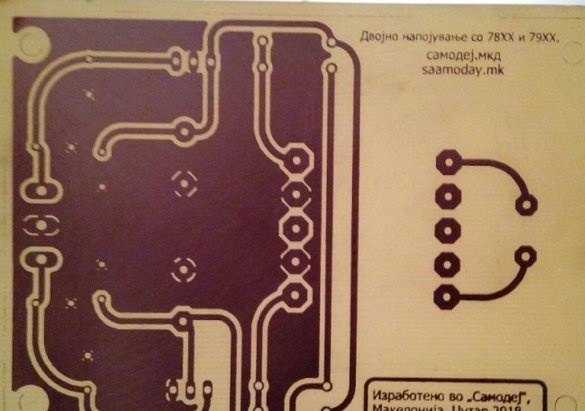
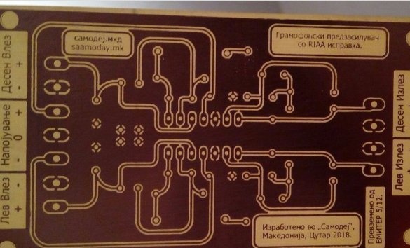
Zoran.Velinov made LUT so: printing on glossy paper, transferring onto heated foil by rolling on top of a stainless steel pipe, etching with a composition of 12% peroxide and 15-20% hydrochloric acid, the rest is water.
Boards after assembly:
For some reason, the master decided to solder the terminal blocks into the boards only for the duration of the test, and then unsolder them and solder all the wires directly into the boards. A matter of taste.
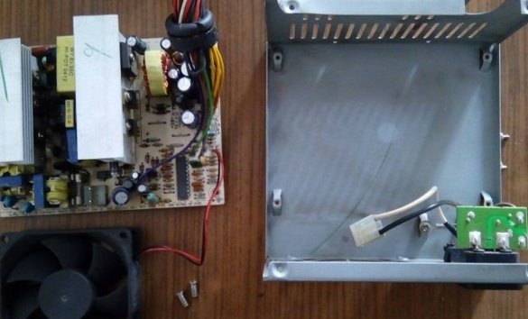
The master parses the computer power supply:
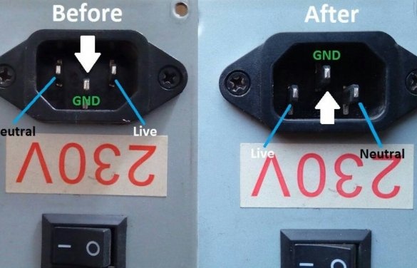
Flips the power connector:
Adhesive to sticker body:
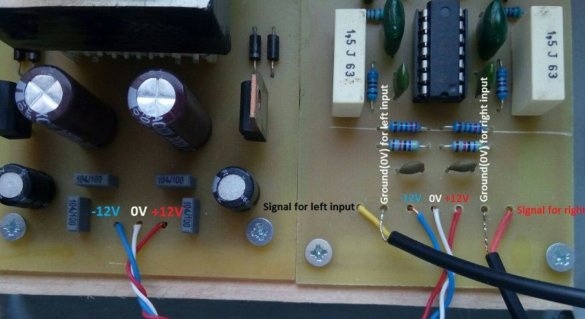
It places its boards inside (an insulating gasket between the case and printed conductors is mandatory), connects them by power, connects the input cables:
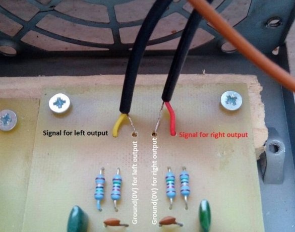
And output cables:
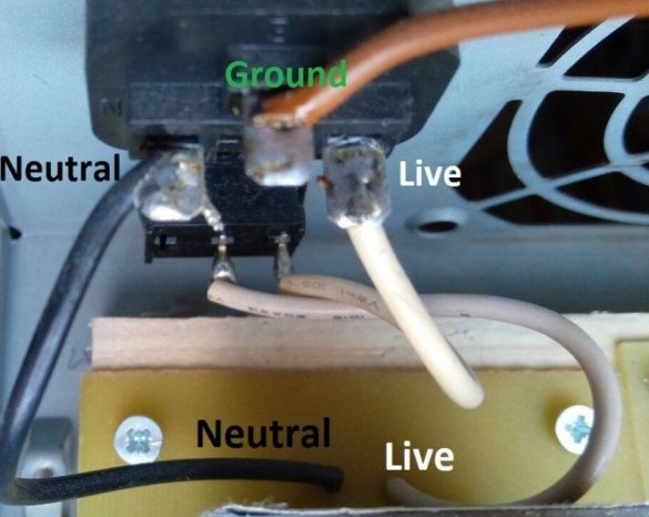
Connects the power connector through the switch to the power supply board (WARNING! And I would add a fuse here):
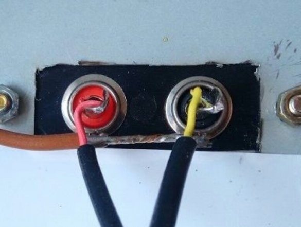
Connects input tulips:
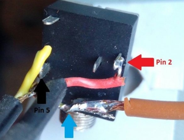
Switch for sharing the common wire and ground:
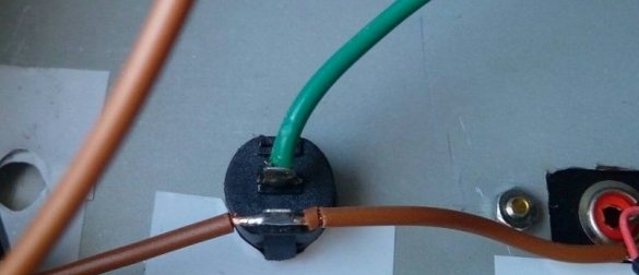
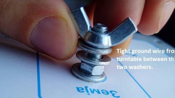
Ground terminal:
On the back side:
Connects an output three-pin jack:
Isolates it from the back side like this:
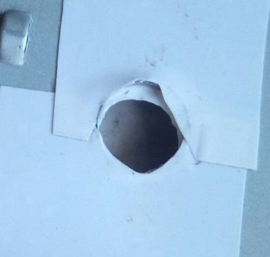
And from the front - like this:
Admires the result:
Well, now you can connect and listen to everything:
If you are interested in this phono stage, download all the files necessary for its manufacture in one archive.

