
"Electrometer? Yes, so that I voluntarily do it yourselfis this home? Maybe I should also rewrite the chapter from the textbook to the notebook? ” - so the reader will think if he graduated from school recently. And if for a long time, this device will cause him other feelings. As, however, is a simpler petal electroscope (physical cabinets usually have both), but there are a lot of them on Instructables, they are somewhat rude, and the torsion electrometer made by the author under the nickname AndresR145 is one that differs from them in a rather high quality of performance .
Of course, you will have to invest more labor in it than in an electroscope “in five minutes from a bottle”. The photo shows only part of the materials necessary for its manufacture.
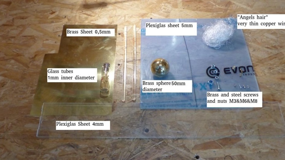
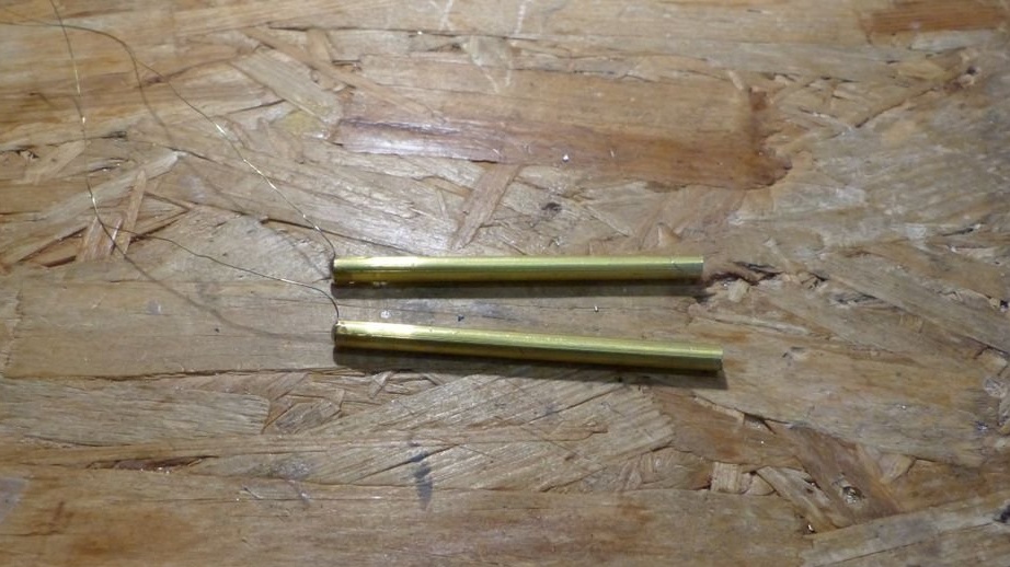
This is 0.5 mm thick brass sheet, 4 and 5 mm thick plexiglas, a 50 mm diameter brass ball with an M8 thread, two plexiglass rods, each 10 mm in diameter and 250 mm long, very small copper wire sections, nuts and screws M3, M6, M8. Didn’t get into the frame: steel wire with a diameter of 1 mm, brass wire with a diameter of 1 and 0.2 mm, two brass rods with a length of 60 mm and a diameter of 4 mm, two different aluminum rods: one with a length of 25 mm and a diameter of 10 mm, the second length of 10 mm and a diameter of 6 mm, three wooden legs.
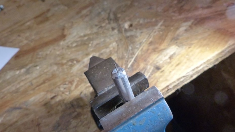
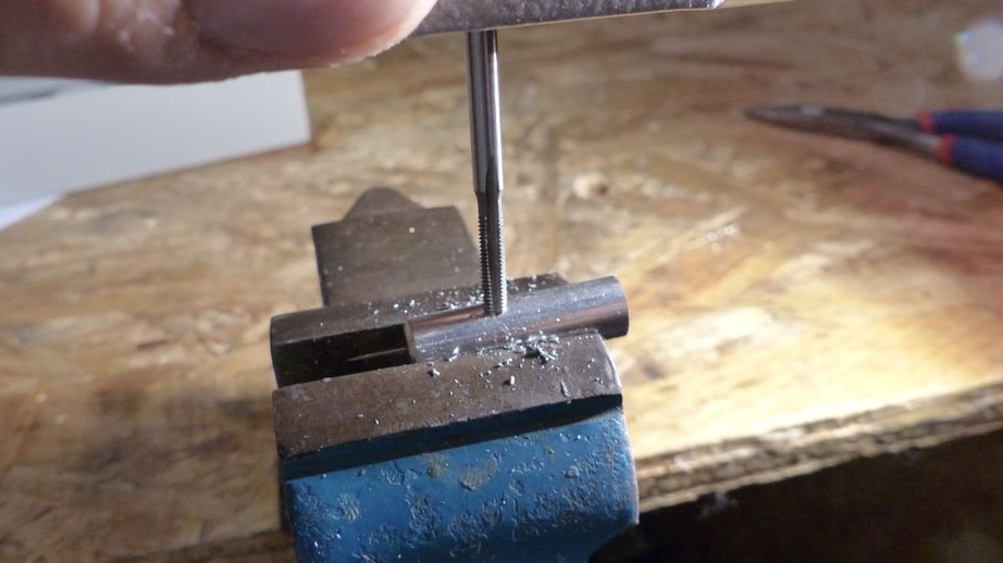
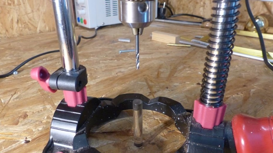
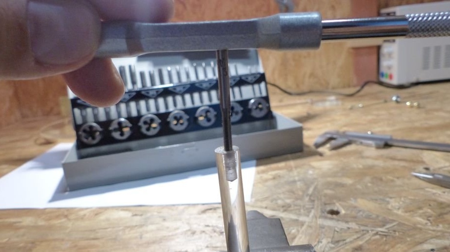
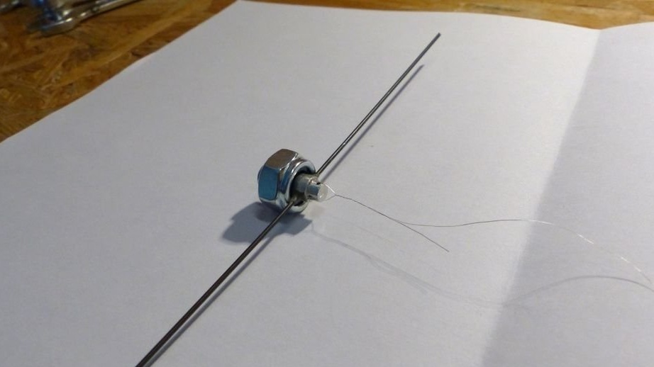
An aluminum rod 10 mm long was made by a master on a lathe. At the end of the rod, he drilled a hole with a diameter of 0.8 mm, into which he placed the needle and fixed it with superglue. On the side, as well as in the opposite end, he drilled a hole with a diameter of 2.5 mm, in each of which he cut an M3 thread. In the photo, AndresR145 showed only the fixing of the needle and threading:
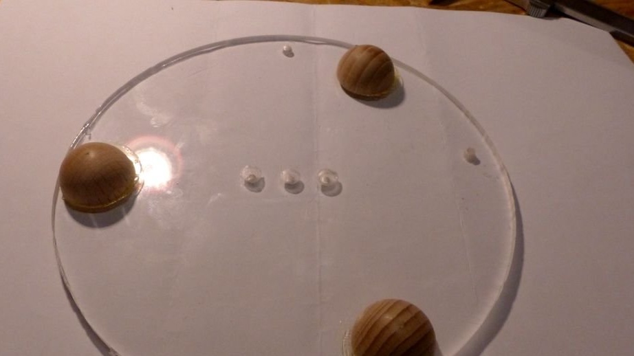
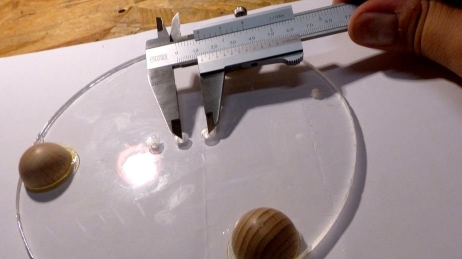
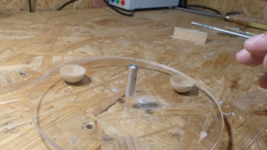
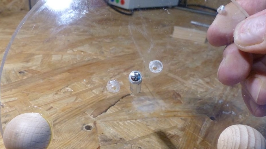
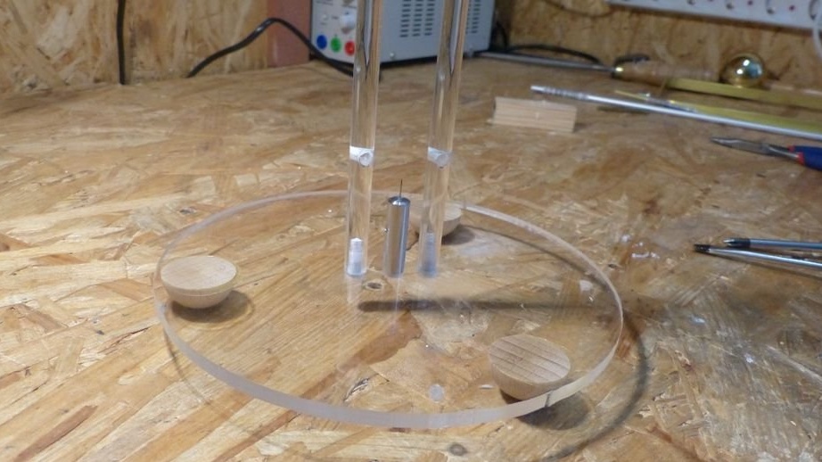
From plexiglass 5 mm thick, the master cut a circle with a diameter of 160 mm. I glued three wooden legs to it. I drilled a 3-mm hole in the center, then two more of the same ones on the sides of it at a distance of 12 mm from the central one. With a 7 mm drill on the side where the legs are, he made holes in the holes for the countersunk heads of the screws. In the center, I fixed the rod with the needle made in the previous step:
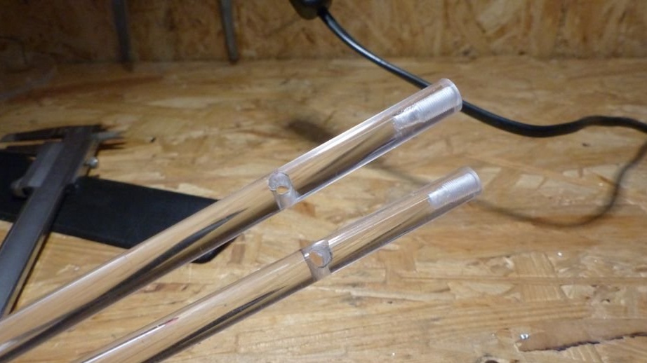
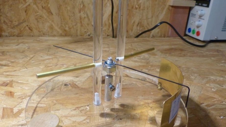
At both ends of both plexiglass rods, the master drilled holes with a diameter of 2.5 mm and cut an M3 thread into them. Having retreated 32 mm from one of the ends, he drilled a 4-mm hole in each side of the rod perpendicular to the axis so that the perpendicular holes in the rods were at the bottom. He fixed these rods in the remaining holes in the stand.I soldered 0.2 mm brass wires to the brass rods, which I placed in perpendicular holes in the plexiglass rods as shown in the photo:
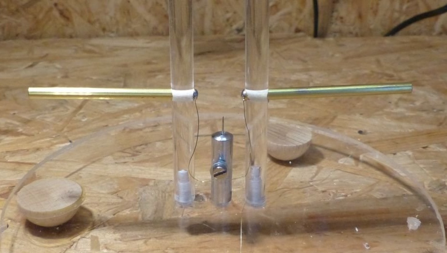
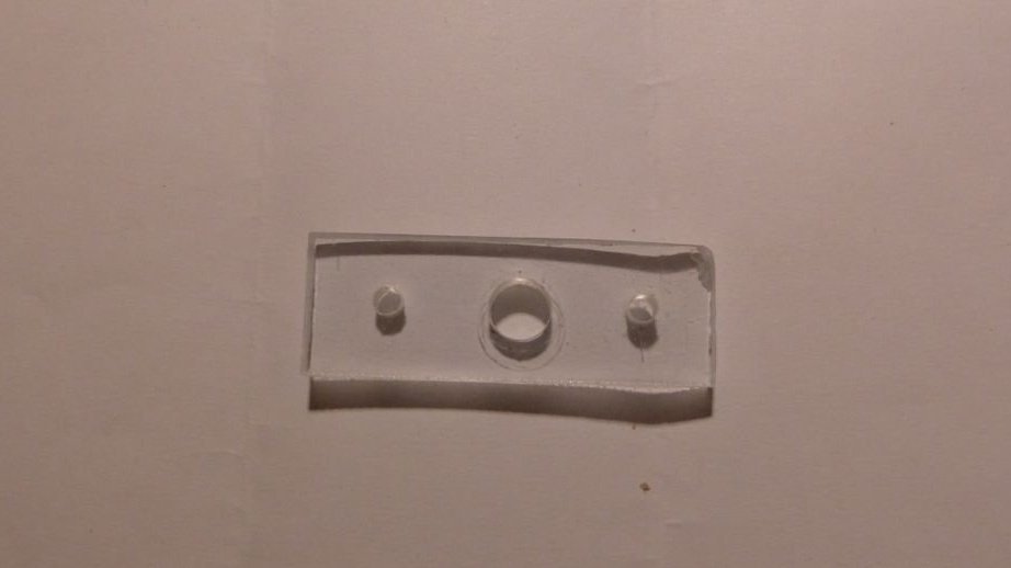
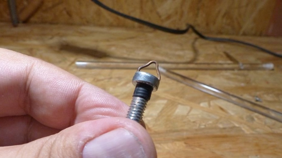
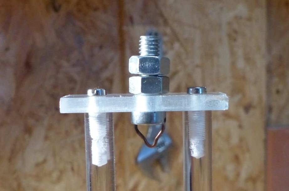
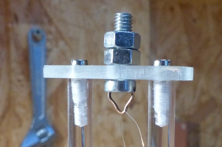
From a 4 mm thick plexiglass, the master cut a rectangle measuring 40x15 mm. In the middle of it, he drilled a hole with a diameter of 8 mm, and on the sides, at a distance of 12 mm from it, a 3 mm hole. A triangle, resembling a miniature hanger in shape, was bent from a 1 mm brass wire. Soldered it directly into the slot of an M8 screw 25 mm long. At the beginning of the thread of this screw, he placed a shrink piece of 4 mm long. All this is connected together and secured to the plexiglass rods as shown in the photo:
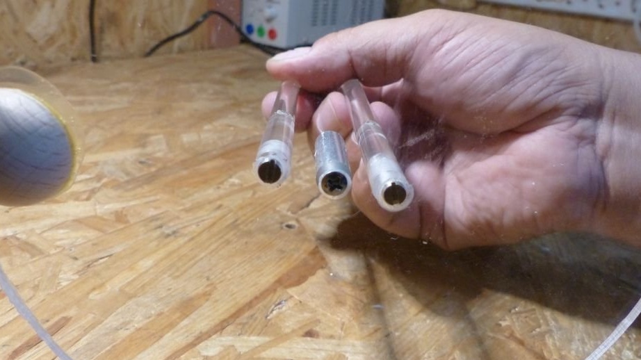
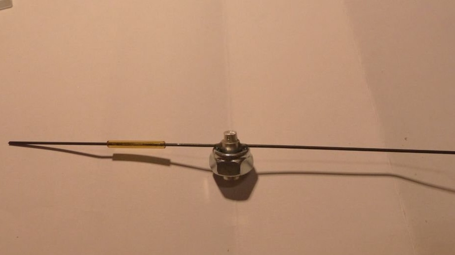
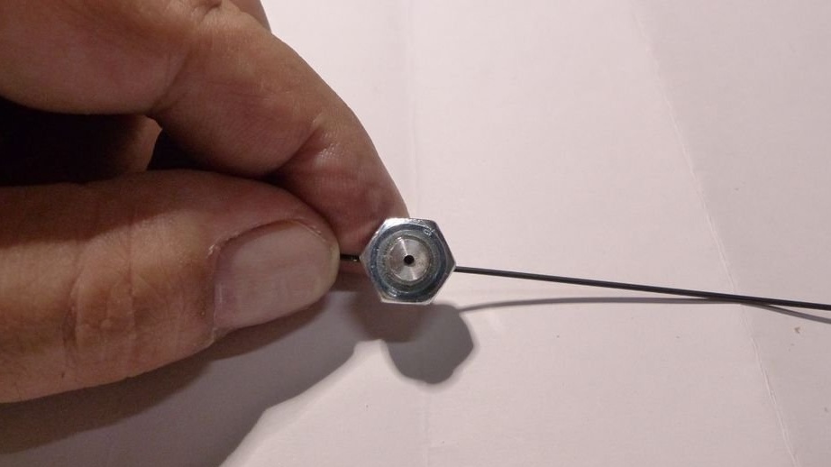
Taking a small segment of a 6 mm aluminum rod, the master gave it on the lathe the form shown in the photo. From one of the ends he drilled a 0.5 mm hole for the spring, from the other - a 0.8 mm hole for mounting on the needle. Across the axis, I drilled a 1 mm hole for the arrow. He weighted the part with an 8 mm nut, glued it, attached an arrow from anodized steel wire, balanced it with a piece of glass tube that can be moved:
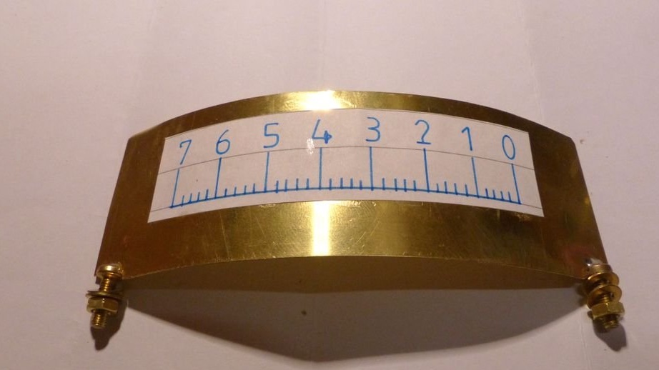
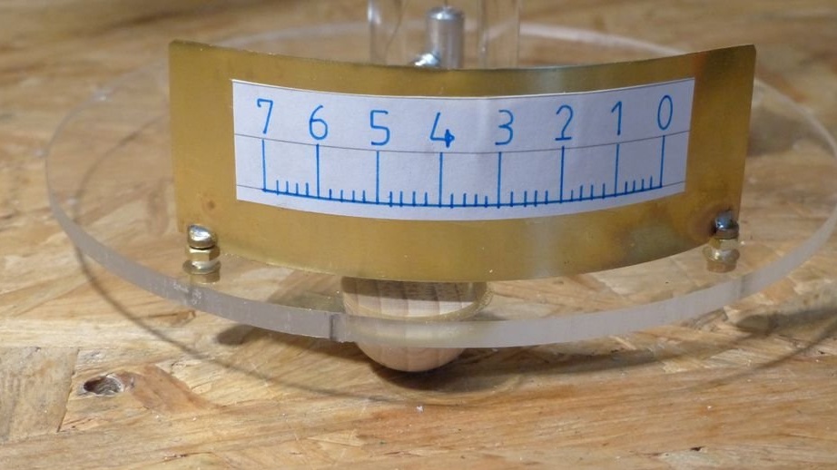
The base of the scale with dimensions of 120x35 mm AndresR145 cut from a brass sheet and bent. I glued the scale (conditional graduation, like a school electrometer). I soldered two M3 screws, drilled two more holes in a plexiglass stand, fixed everything:
I made a spring out of a very thin copper wire, secured it with one end on the rotating part using the hole provided for this, the other on the “hanger”, and put the rotating part with the arrow in place:
Well, there was only a ball in which the M8 internal thread is already there:
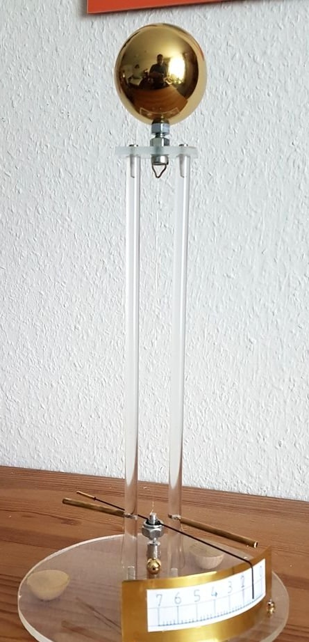
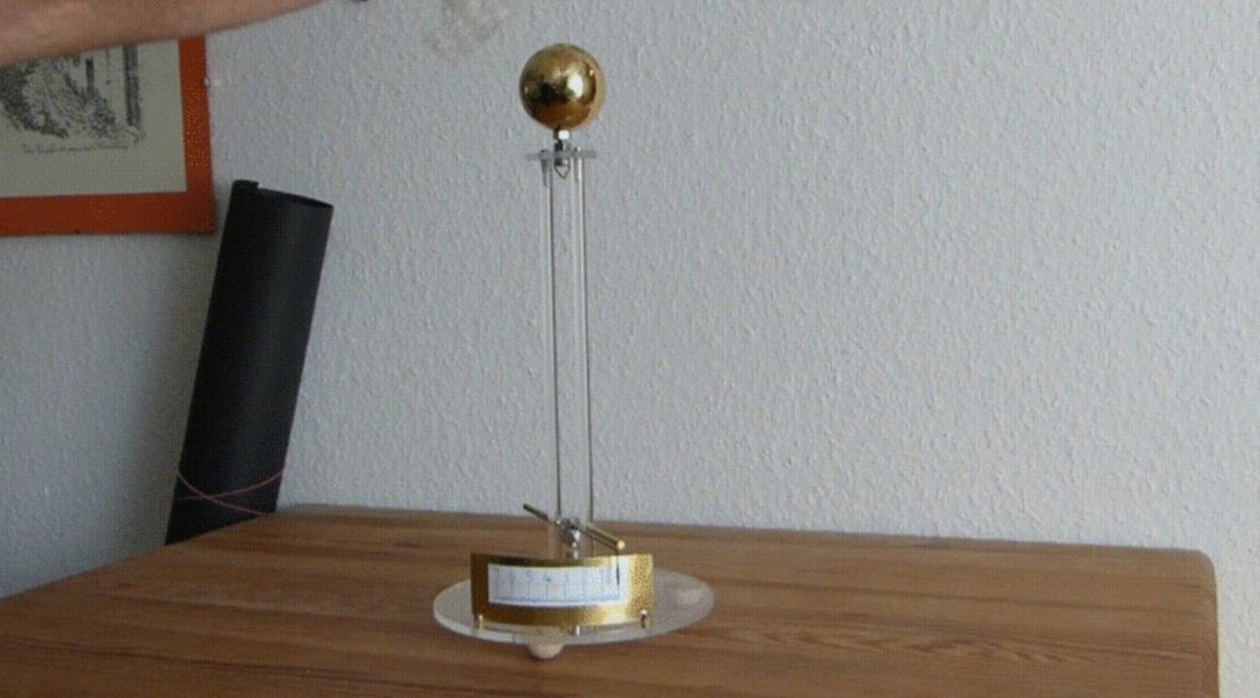
Now the electrometer must be left alone for several minutes so that the needle stops oscillating for purely mechanical reasons, and slowly turn the ball to set the arrow of the discharged electrometer to zero division. In this case, the horizontal rods should be close to the arrow and the counterweight in such positions that the distance increases when the arrow moves to the next divisions. And you can repeat the experiments from the textbook! Only no Leiden cans and other high voltage capacitors, electronic first remove the equipment away, but ebonite, which is no longer being done, can be successfully replaced with a “little bubble”.