
Imagine that you are riding in a children's electric car, the gas pedal of which has only two positions: either the engine is completely turned off or it rotates at a fixed speed. All in all, a simple switch is there. Your task is to reduce the speed, for example, by half. You can turn on a powerful resistor in series with the engine, which will generate a lot of heat. And you can quickly press and release the gas pedal. You will go jerky, the more noticeable, the lower the frequency, but the average speed will decrease as you need. By changing the ratio between the time the circuit breaker is on and off - duty cycle - you can change the average speed. And the switch almost does not heat up, because its resistance tends to infinity, then to zero. Almost all power will be allocated to the engine. Why this happens, it is easy to calculate, knowing Ohm's law.
So you understand what pulse-width modulation is, in short - PWM. Everything described above can be entrusted to an automatic device called a PWM controller. It can be complex, containing the whole Arduino. It may be simpler - a two-element generator NAND, a variable resistor and two diodes. And it can be quite simple - on two transistors (compare this with how many transistors are in the Arduino):
This is called the KISS principle, from "keep it simple, stupid". Of course, not in the literal sense - in fact, it is understood that a designer striving to simplify designs, on the contrary, is very smart, because this increases reliability, maintainability and visibility. True, at the cost of additional protection, flexibility and freedom of reconfiguration.
It is clear that the engine of a children's electric car mentioned in the example will pull this circuit only with an additional cascade. And without it - only a small motor from a toy. But the principle of operation of the PWM controller is shown as clearly as possible.
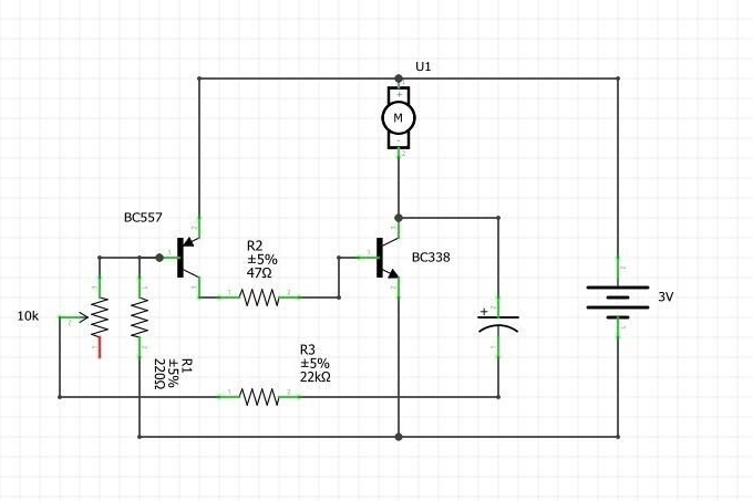
This circuit, which was invented for you by Instructables under the nickname TheCircuit, is an asymmetric multivibrator with transistors of different structures. Exactly the same as B.S. Ivanov, V.G. Borisov.Only two resistors have been added to it: a variable resistor and a constant connected in series with it, so that the resistance of the entire chain does not become too low. They are included in the circuit so that when adjusting the duty cycle of the vibrations generated by the multivibrator changes.
The use of transistors of different structures in a multivibrator allows you to reduce the number of capacitors in it to one. Here it is electrolytic, at 100 uF and 60 V, this voltage is chosen with a good margin. Resistors: constant - 47 Ohm, 22 kOhm, 220 kOhm, tuning (you can apply a large variable) - 10 kOhm. Transistors - BC557 and BC338. The power source is two AA or AAA elements, better than salt elements, so that if something goes wrong, nothing gets too hot. The load is a low-powered electric motor from a toy. In parallel, it is good for him to connect a diode in reverse polarity. It will take on the self-induction pulse that occurs when the motor is suddenly turned off, and will protect the transistor from it.
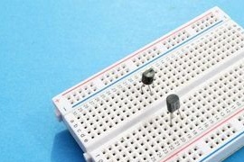
Since TheCircuit assembles the device on a breadboard-type breadboard, the order in which the components are installed does not matter. So, he sets the transistors first. If you will assemble this regulator by soldering, put the transistors last so as not to overheat them.
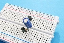
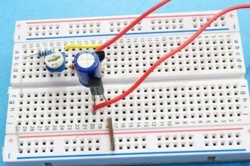
Then the master puts the capacitor on the board in the correct polarity:
Resistors:

Jumpers:
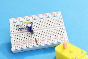
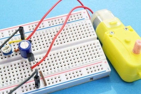
Connects the engine:
If the engine will simply lie on the table, the polarity of its connection is not important, and if you move any mechanism, it is important to connect it so that it rotates in the desired direction. By the way, the developer took the engine with a gearbox, which increases the visibility: it is clearly visible and in which direction it rotates, and at what speed. But the polarity of the power supply connection must coincide with the one indicated on the diagram: plus at the top. Here the master gets to him:
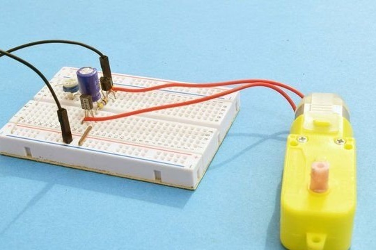
Now you can rotate the tuning resistor (or a variable, depending on which one you set), watch how the speed changes, and make sure that the heating of the second transistor at any speed is small (and the first and even more so). Now complete the circuit with a switch connected in series with the power source, and add a housing.