
On the websites of Aliexpress, Adafruit, Amperka and the like (not only the letter A), you can find modules of touch buttons. They are very convenient: connected this to a digital input Arduino (or just a counted trigger) - and he “thinks” that this is a normal mechanical button with a pull-up resistor and a bounce suppression circuit. The author of Instrictables under the nickname TheCircuit suggests doing the same thing, but do it yourself. Let's see how.
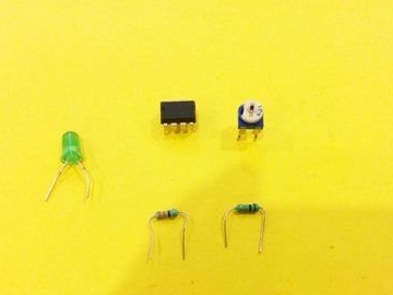
The structure includes: operational amplifier LM358, two permanent resistors - 330 Ohms and 10 kOhm, one trimmer for 10 kOhm and an LED:
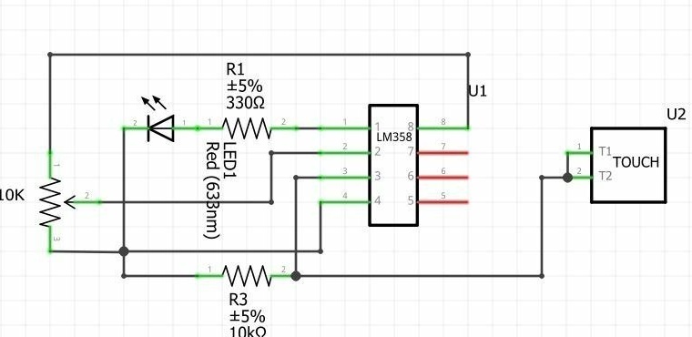
The wizard assembles the module according to this scheme (of course, the sensor plate has one output, and not two parallel ones):
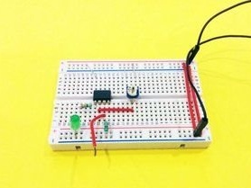
First on a breadboard type breadboard. Places components and jumpers, connects. The only two-pin polar component here is the LED.
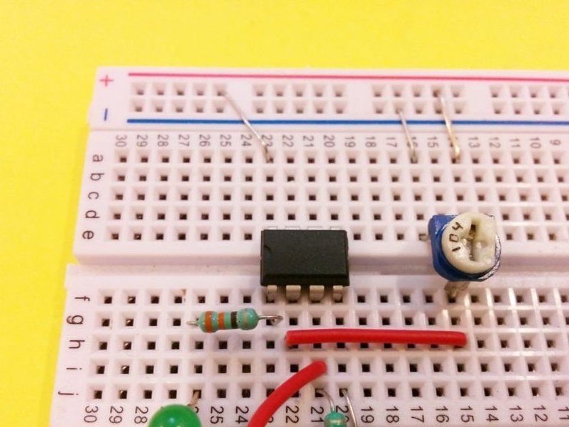
It connects the power wires in the correct polarity, but so far it does not supply power:
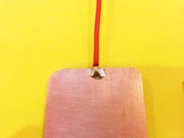
Attaches a touch plate:
It turns on the power (3.3 or 5 V, when working in conjunction with an external device, the power source must be shared). The trimmer adjusts the sensitivity so that when you touch the sensor plate, the LED glows, but when released, it doesn't. That's all it works:
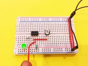
The signal to the external device should be removed from the connection point of the right one according to the output circuit of the resistor at 330 Ohms with pin 1 of the chip. Touch will correspond to a logical unit - as with ready-made touch-button modules.
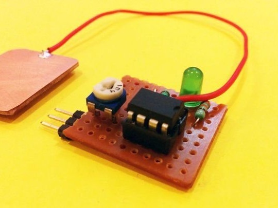
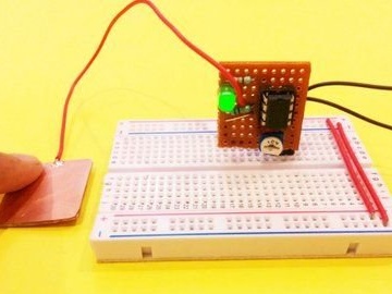
The master transfers the debugged circuit to a more compact breadboard like perfboard, adds a three-pin comb (power, output, common) and a socket for the microcircuit, which allows not to overheat it when soldering:
After the transfer, an additional sensitivity adjustment with a trimming resistor may be required. You can, of course, build and debug the circuit right away on perfboard. The comb allows, in particular, to put the module in the breadboard vertically, as if it were one component:
A device, in which one or more of these modules will operate, must have galvanic isolation from the network. The power source used during verification and debugging is also affected.