The author of Instructables under the nickname RimvydasP already made such a shield, but on the TEA5767 chip. And everything there was wonderful, except for the lack of RDS. As soon as the master found out about the existence of the Si4703 chip, where this function is, he immediately took up a new shield.
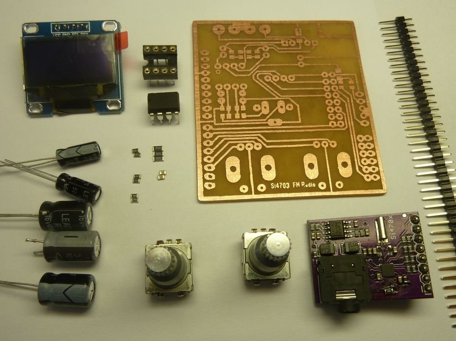
The RimvydasP device was based on a commercially available adapter board, on which this chip was already soldered. To display information, incl. frequencies and RDS lines, he used an OLED display with a resolution of 128x64 pixels, connected via an I2C interface. The amplifier, as in the previous shield, made it on the TDA2822 chip. To control the volume and tuning, neural interfaces are used ... just kidding, encoders, and with Arduino the shield is connected by combing. All this, together with resistors and capacitors, is shown in the photo (jack and terminal blocks were behind the scenes):
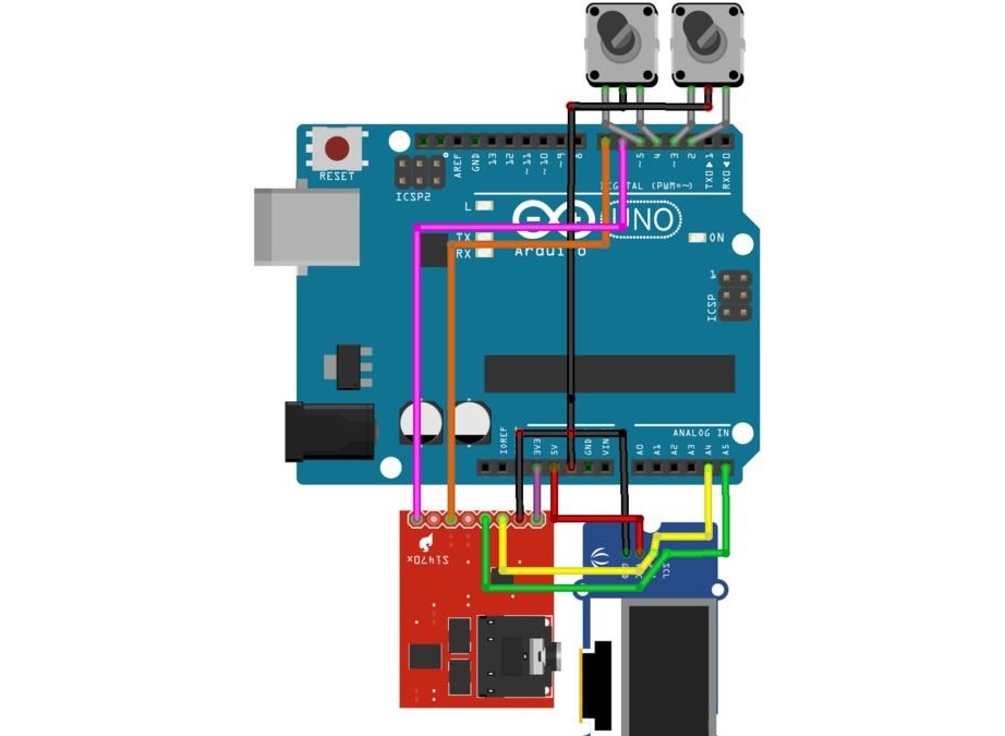
How encoders, receiver board and display are connected to Arduino are shown in the diagram. Due to the features of the applied software, it was not possible to depict the amplifier:
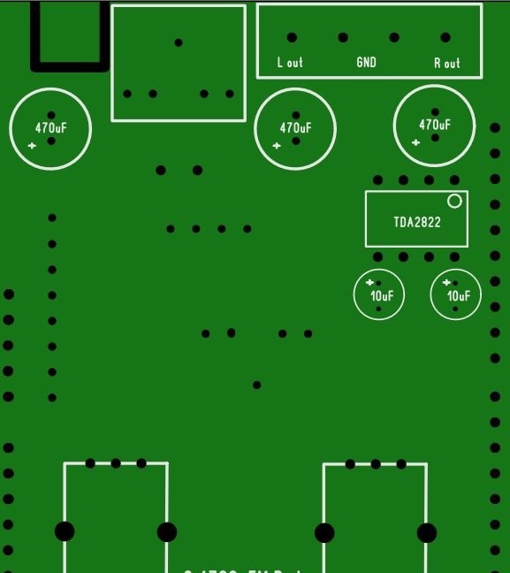
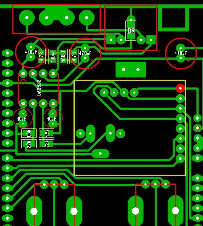
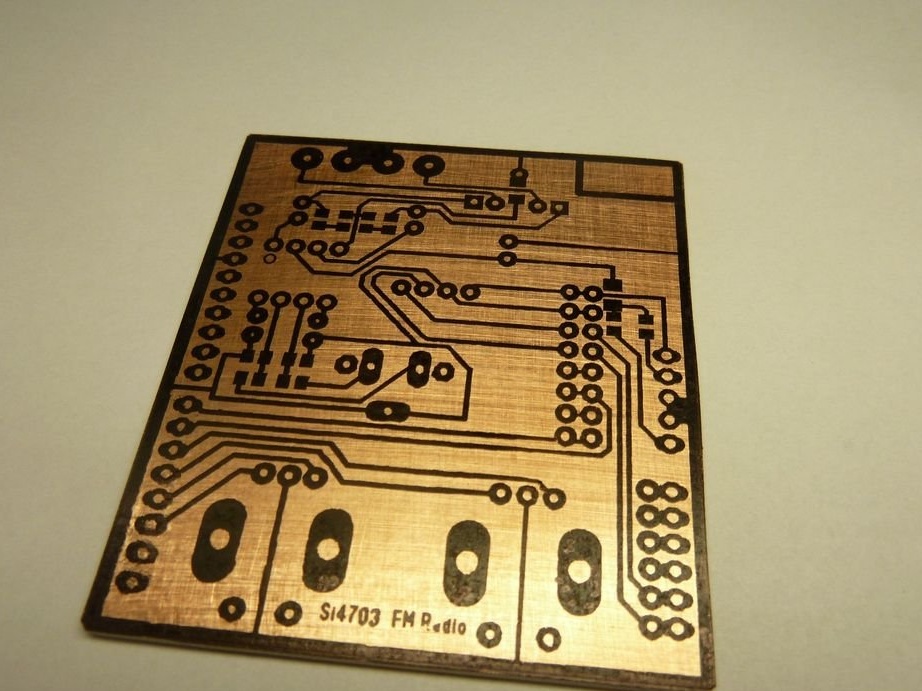
The master designed the circuit board of the shield itself. One way, by the way. These illustrations show which, where and how to solder capacitors and resistors, and how to deploy an amplifier chip before soldering. 0R is an SMD jumper, you can use a simple jumper.
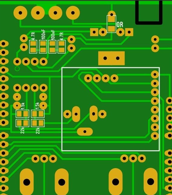
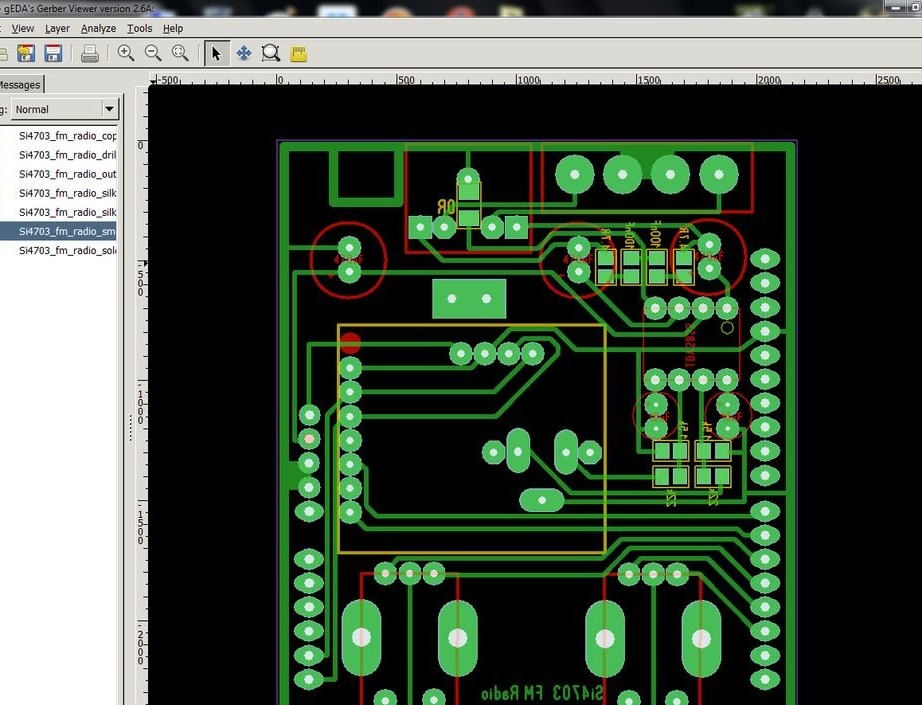
You can download board related files in formats Sprint layout and Gerber (archived). Sketch uses libraries Si4703_Breakout.h and U8glib.h.
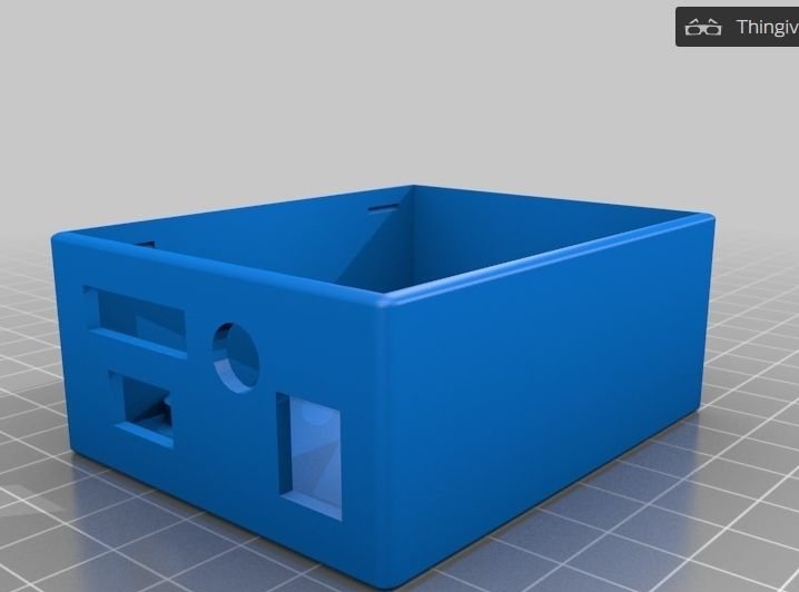
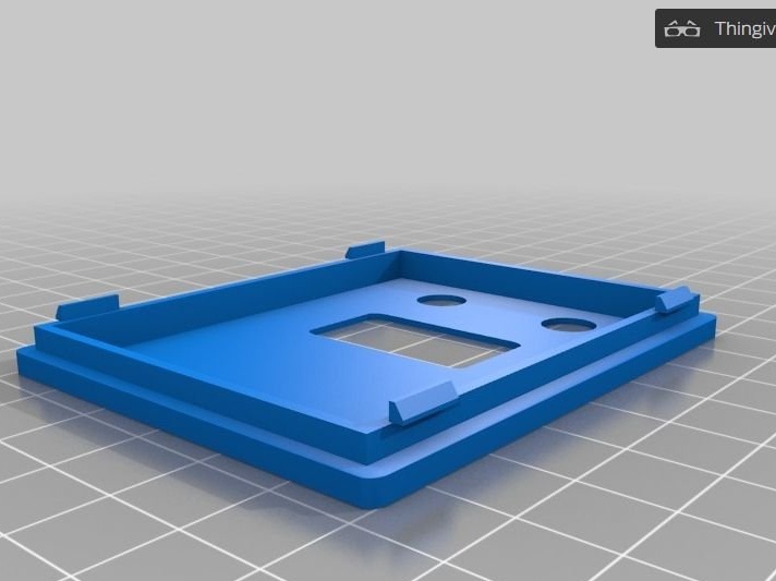
The casing for Arduino along with the shield was printed by the master, although you can simply make holes in a suitable box. He laid out all the necessary files on thingiverseas well as directly on Instructables: the case itself and top panel. So it looks on the screen:
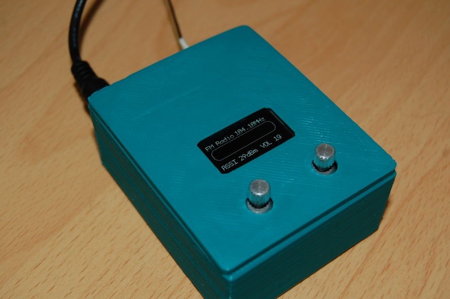
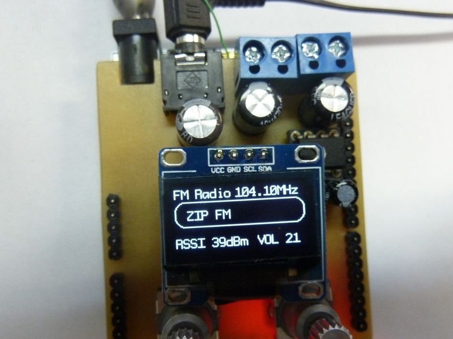
And so - in real life:
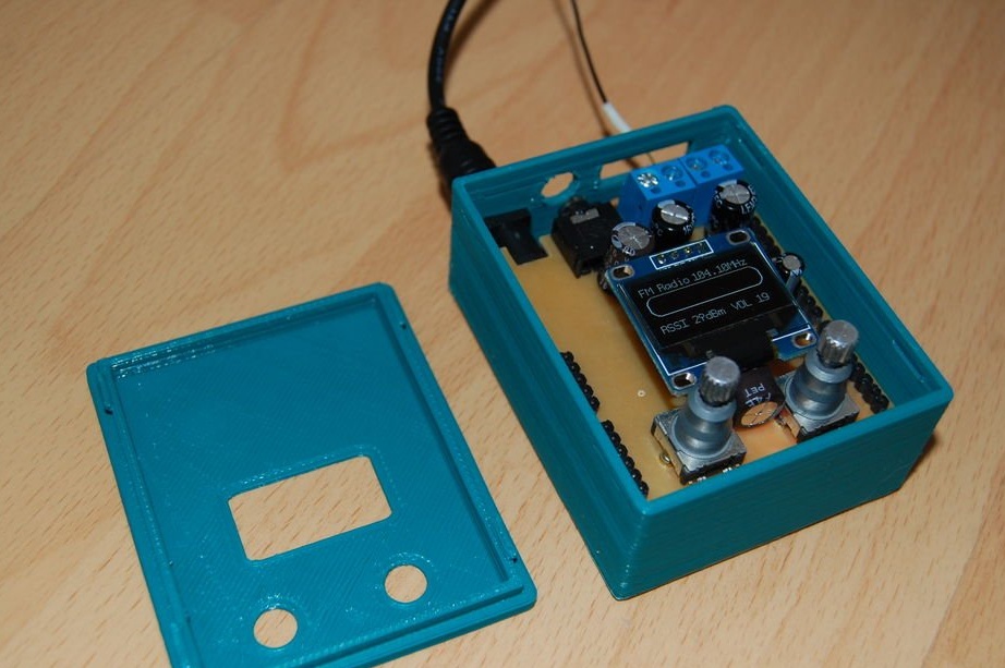
Please note that the receiver board is soldered to the shield board from the side of the conductors, so the comb should be taken high enough, and the antenna wire should be insulated:
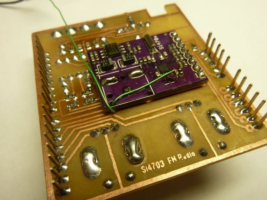
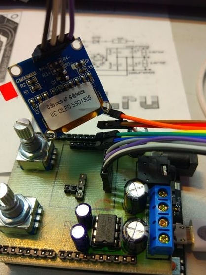
The display is soldered from the side of the components, where there is more than enough space. And he, as we see, displays the RDS line:
The author reports that the noise from the boost converter in the OLED display somewhat degrades the sensitivity. There are displays with the same resolution and interface, but LCDs, they are sometimes installed in makeshift Arduboy clones, here you can also do this.
A repeat of this shield was reported by an Instructables member under the nickname leoo13: