Sometimes there is a need for a simple doorbell that has sufficient volume and contains a minimum of detail.
Doorbells have many variations of appearance, sound and internal "filling." By pressing the bell button, you can hear a ringing or buzzing, or you can hear the sounds of classic Beethoven and Mozart tunes or a melody of a popular children's song. This sound of the ringer is provided by the music module, which is located inside. A music call can be made do it yourself, and this activity is not at all difficult.
After reading the article, you will learn how to make a simple doorbell do-it-yourself doorbell.
A musical bell is no longer a novelty in our apartments. However, industrial products have several disadvantages.
In one design of calls, their bell button, according to the canons of electrical safety, is in the secondary circuit of the transformer.
In another version, of course, with a short-term operation of the call, the battery will last for a long time. But when it is discharged, it is difficult to predict, and their prices bite. According to my concepts, an apartment call is more expedient and more economical to be powered from the mains.
In addition, the sound quality itself leaves much to be desired, and the signal volume of some serial products is low. And 8 combinations of two sounds “bim” and “bom” can hardly be called a musical composition for a musical call.
The proposed device is devoid of these disadvantages. In standby mode, the call is disconnected from the network, and only after pressing the button connects to it. While the button is pressed, the call works. After releasing the button, the melody stops, and the device again disconnects from the network until the next call. The basis of the device is a music chip with the melody you like.
Currently, various types of children's toys are often used as the basis for home-made doorbells. This approach is associated with a number of advantages, as it allows you to select the desired device parameters - melody, timbre and sound volume.
Apartment Call Scheme
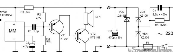
The doorbell diagram shown in the figure consists of a music module MM (extracted from a broken toy) and a simple two-stage audio frequency amplifier assembled on transistors VT1 and VT2.
Since the energy consumption of this design is small, it is quite possible to use a transformer-free mains power supply with a quenching capacitor C4, a rectifier on diodes VD3 and VD4, a zener diode VD2 (12 volts), and a smoothing electrolytic capacitor C3.
As a C4, it is desirable to use a K73-17 type capacitor for an operating voltage of 400 volts or more. The required capacitance of the capacitor C4 can be selected from several similar capacitors of lower capacitance connected in parallel. Instead of the transistors VT1 and VT2 indicated in the diagram, the corresponding imported transistors can be used. The dynamic head SP1 must be 1 ... 2 W, for example, 1GD36, 1GD40, 2GD36, and the resistance of its voice coil is 8 ... 10 Ohms.
Making a music block and audio amplifier
And so, to make a simple but high-quality version of a home-made call, we will use a musical toy. For a specific example, consider making a call based on a music module extracted from a broken toy.
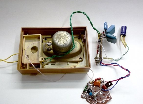
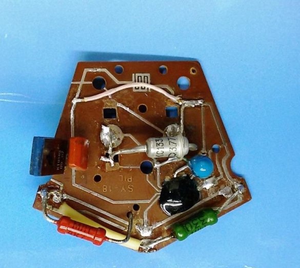
1. Carefully disassemble the toy. Inside the product there should be a small board with a chip-less chip, as well as a battery or battery. The sound source is usually a passive piezoelectric sound emitter (in the photo below, to the left of the board). A black drop on the board, this is an open-circuit microcircuit - a microcircuit chip flooded with a synthetic compound. The findings of the chip are made in the form of foil printed tracks.
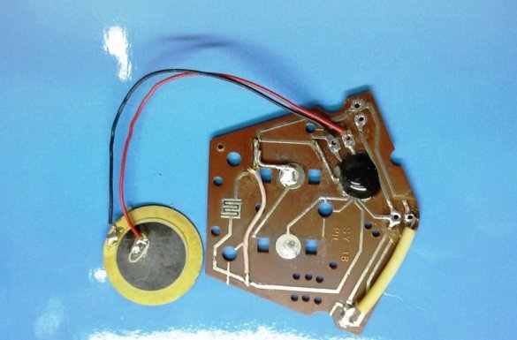
When disassembling a toy, we find a button to turn on a melody fixed above special contacts (in the form of a maze) near the microcircuit. When disassembling the toys, we remember (or even better sketch), to which contacts the piezo-emitter (microcircuit output) and the battery are connected, taking into account the polarity.
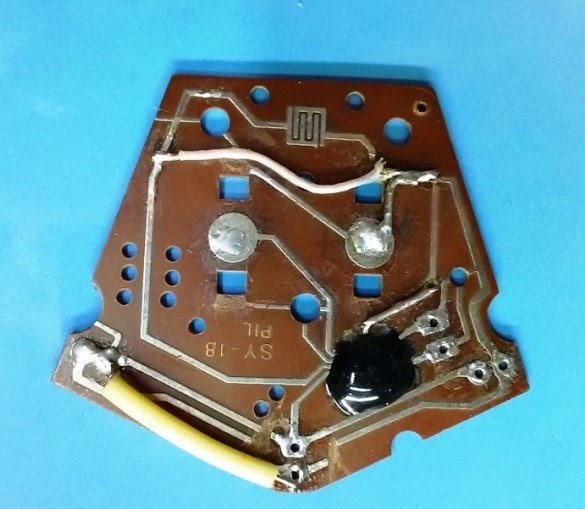
2. Determine the paths involved in the operation of the chip. Excessive tracks for work, if necessary, cut. We restore the missing connections. These operations must be done with the utmost care. Since foil tracks are extremely openwork, you can accidentally tear one of the conductors from the chip or overheat it when soldering. Restore the track will not work.
As a result, we need to determine the (+) and (-) contacts for power supply and the output contacts of the music microcircuit for its connection to the audio frequency amplifier. We find these 4 main contacts and clean them by soldering.
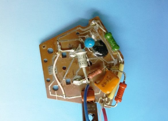
3. Due to the fact that on the given board, the open-circuit microcircuit takes up little space and most of the board’s area is free, we will collect an audio frequency amplifier on it. For the installation of parts, we use the holes on the board (or newly drilled in an empty place) and free printed tracks obtained during the preparation of the board.
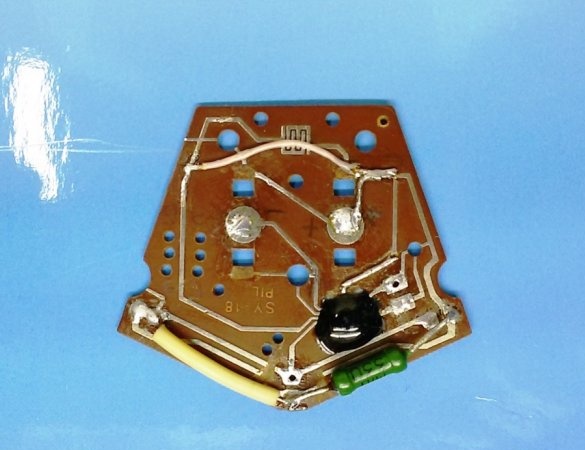
Since the button to turn on the melody is not needed - the sound will turn on when power is applied, close the contacts of the button with the conductor (in the photo - at the top of the board). We install on the board the limiting resistance R1 and the Zener diode VD1 (1.33 volts). These details determine the operating mode of the MM unit, since such a musical microcircuit operates in the power range from 1.2 to 1.8 volts and consumes low current (up to 20 mA).
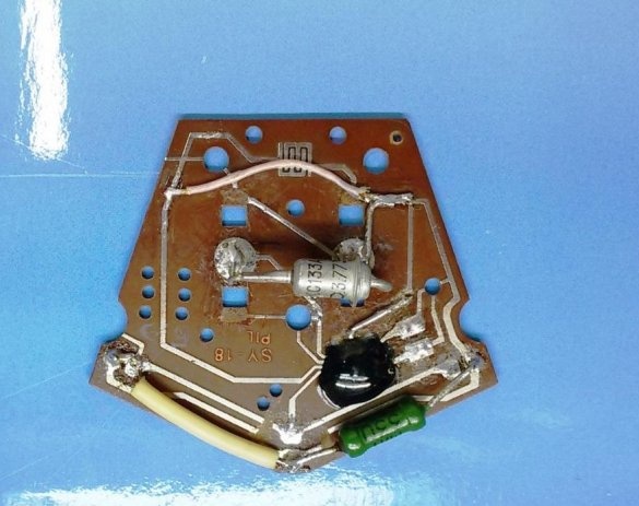
4. We install transistors VT1 and VT2 in the holes in the board and mount the remaining parts of the audio amplifier in a mounted installation in accordance with the above diagram.
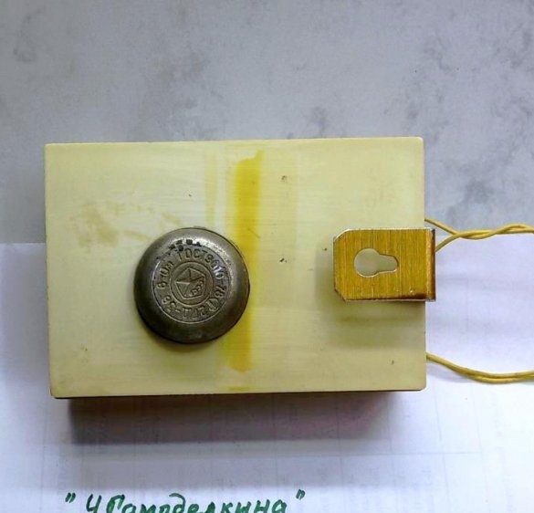
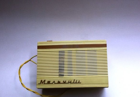
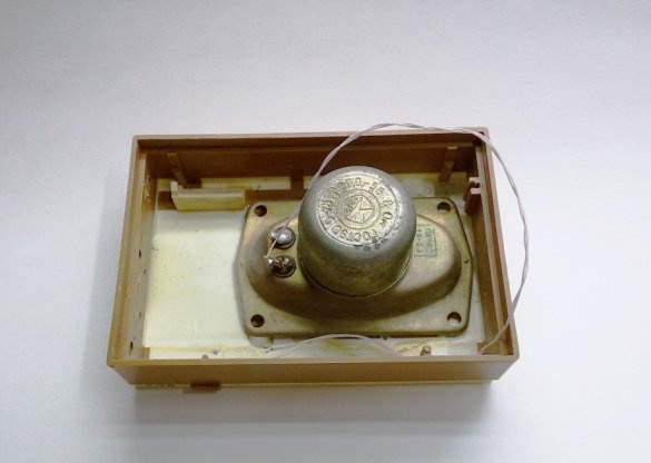
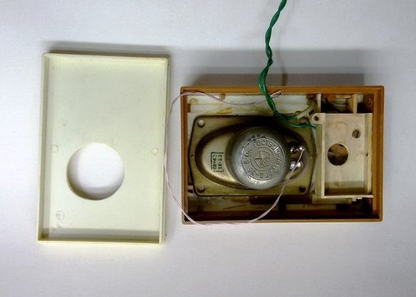
5. Choice of housing for the call.
As an enclosure for assembling a music call, you can use an already unused broadcast subscriber loudspeaker or an intercom with a loudspeaker located there. In the given device, a case was used from the set of a beginner amateur radio amateur - the Malchish radio receiver. The components of the kit have long gone homemade, it's time for the hull. A battery compartment is left with a power switch mounted there. The loudspeaker has been replaced by a more powerful one. To do this, in the back cover, I had to cut a hole under the speaker’s magnetic system.
6. Production of transformerless power supply
To power the device we use a transformerless network power supply.This design of the power supply has great advantages - it is small in size, weight and heat dissipation. The proposed AC power supply for the call made it possible not only to abandon the traditional step-down transformer, but also to somewhat revive the “voice” of the call.
But every good thing has a drawback, in this case, the lack of galvanic isolation from the network.
In this case, subject to the rules of electrical safety, the advantages of this design prevail over the disadvantage.
The voltage from the network enters through the reactance of the capacitor C4 and drops to 18 ... 20 volts. After disconnecting from the network, an impressive charge remains on C4 for a long time. To discharge the capacitor after operation, a high-resistance resistor R4 is connected in parallel with it, through which the capacitor is discharged. The rectifier of the power supply unit is half-wave, works on diodes VD1 and VD2. Voltage at 12 volts, supports Zener diode VD2. Capacitor C3 smooths out ripples and works as an energy storage device to keep the power more stable during the sound of a call.
We select a small board for mounting the power supply, place and solder the parts on it in accordance with the above diagram.
7. Music ring test
We connect the music module with the manufactured power supply.
Properly assembled, from serviceable parts, the device does not need adjustment.
The first inclusion, testing and use of a call with transformer-free mains power requires increased attention and caution. Otherwise, you can not only get under high voltage, but also instantly “burn” the chip and transistors.
To avoid such troubles, first of all, check the correct installation of the structure. Then, in order of safety, disconnect the conductors from the power supply to the transistors of the amplifier and the music module.
Turn on the power and measure the voltage at the SZ filter capacitor. If it does not exceed 18 ... 20 V, which indicates the normal operation of the power supply, then you can restore the connection between the power supply and the amplifier (after disconnecting the call from the network) and measure the voltage in the power supply circuit of the music module. Here it should be within 1.2 ... 1.8 V. If so, then the call design is ready for final assembly.
8. Build a music bell
We collect the design of the bell in the prepared building. The design of the call is connected to the 220 volt network via the bell button S1, calculated on the mains voltage. By pressing the S1 button, test the finished call at work.