» Electronics » Arduino »Pseudo-wooden LED watch

Pseudo-Wooden LED Watch


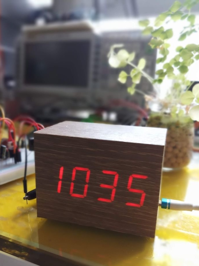
A wooden watch in the shape of a parallelepiped, where the LED display shines through a thin veneer, is not a novelty for a long time. They are commercially available and have been in demand for ten years now. And this Instructables watch by the nickname Darwin Energy is pseudo-wooden: its case is made of plastic, and instead of veneer it is a vinyl film with a similar pattern.

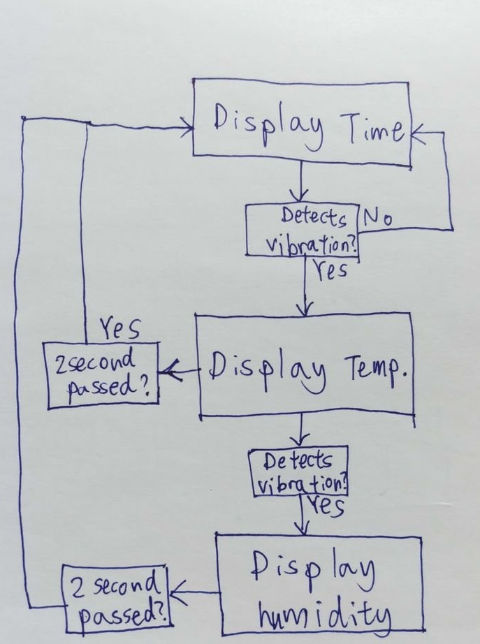
To select the clock, thermometer and hygrometer modes, the developer used a vibration sensor. The algorithm for switching between modes is as follows:


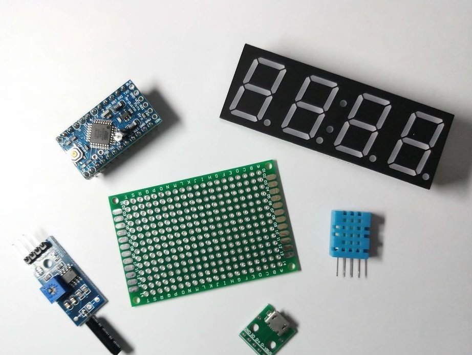
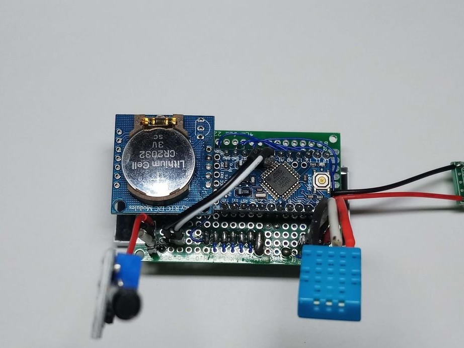
The master assembled the clock on a perfboard type board from the following components: Arduino Pro Mini, type 8402AS display, DHT11 temperature and humidity sensor, DS1307 real-time clock, UMProb vibration sensor, module with Tenstar Robot Micro USB socket (you just need to power it, you can just take the USB cable from something broken) . For firmware, he took the module for converting a USB port to a serial Honbay CP2102.


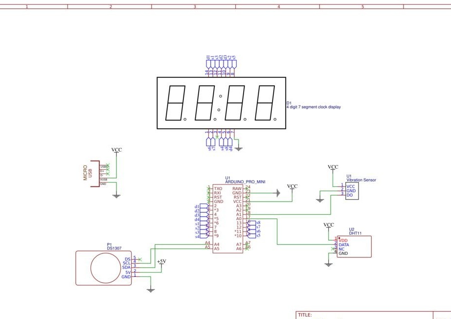
He collected the clock according to the scheme:


Preferring to use combs and sockets for connecting wires to a breadboard with a comb:


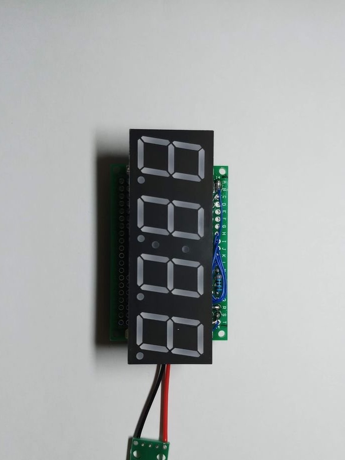
This is how the result looks from two sides:


For users who do not want to flash anything, he recommends purchasing any designer kit for assembling LED watches, choosing one where the microcontroller is delivered already stitched. But then there will be no thermometer and hygrometer modes, as well as a vibration sensor. The developer himself is flashing Arduino with the Honbay CP2102 device already mentioned above:


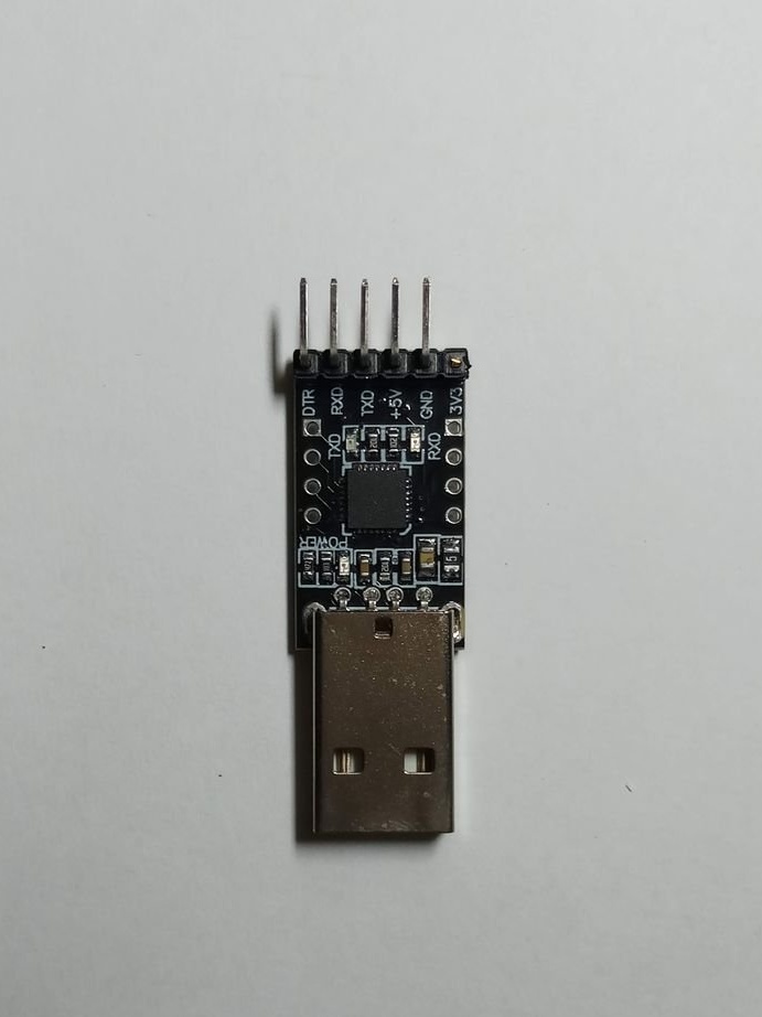
Connecting them like this:

Arduino side ---------- Programmer side

VCC -------------------------------------- + 5V

GND ------------------------------------- GND

GRN ------------------------------------- DTR

TX ------------------------------------------ RX

RX ------------------------------------------ TX

Sketch here.

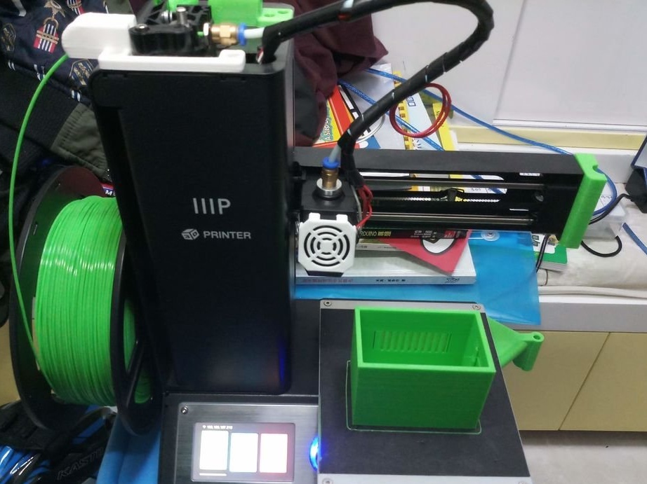
The case can be 3D-printed, or you can take any suitable box in size and cut holes in it. The wizard selects the first:


STL file here.

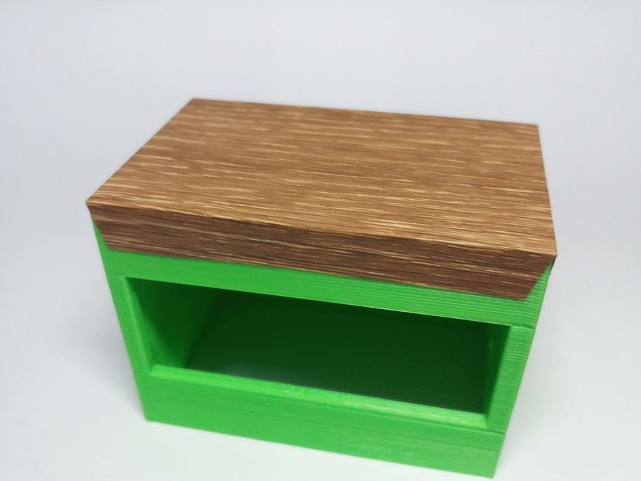
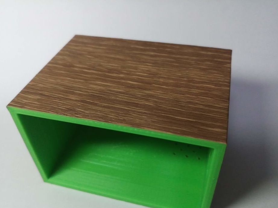
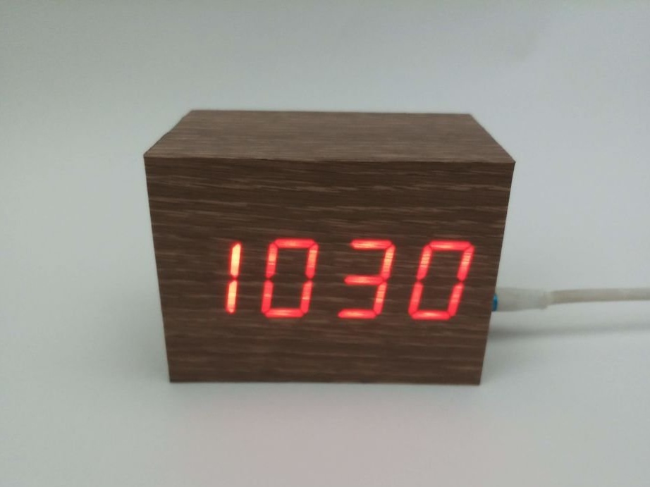
After pasting with vinyl film, the case becomes very beautiful:


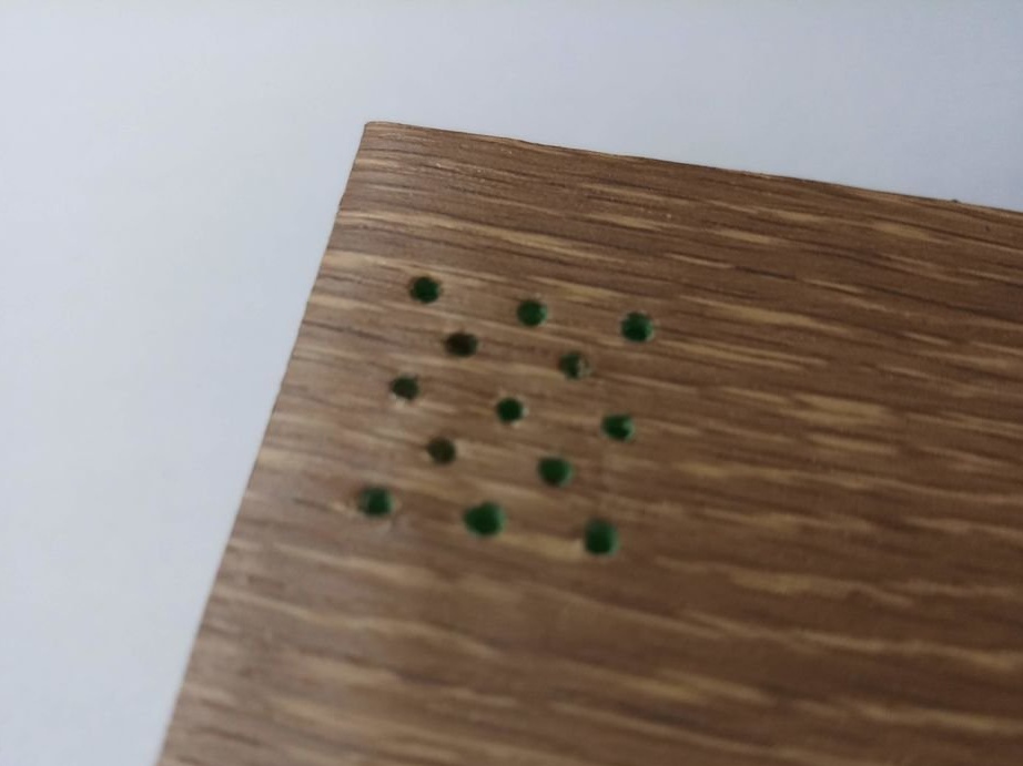
Holes are needed for the temperature and humidity sensor. The wizard shows the optimal location for its location:


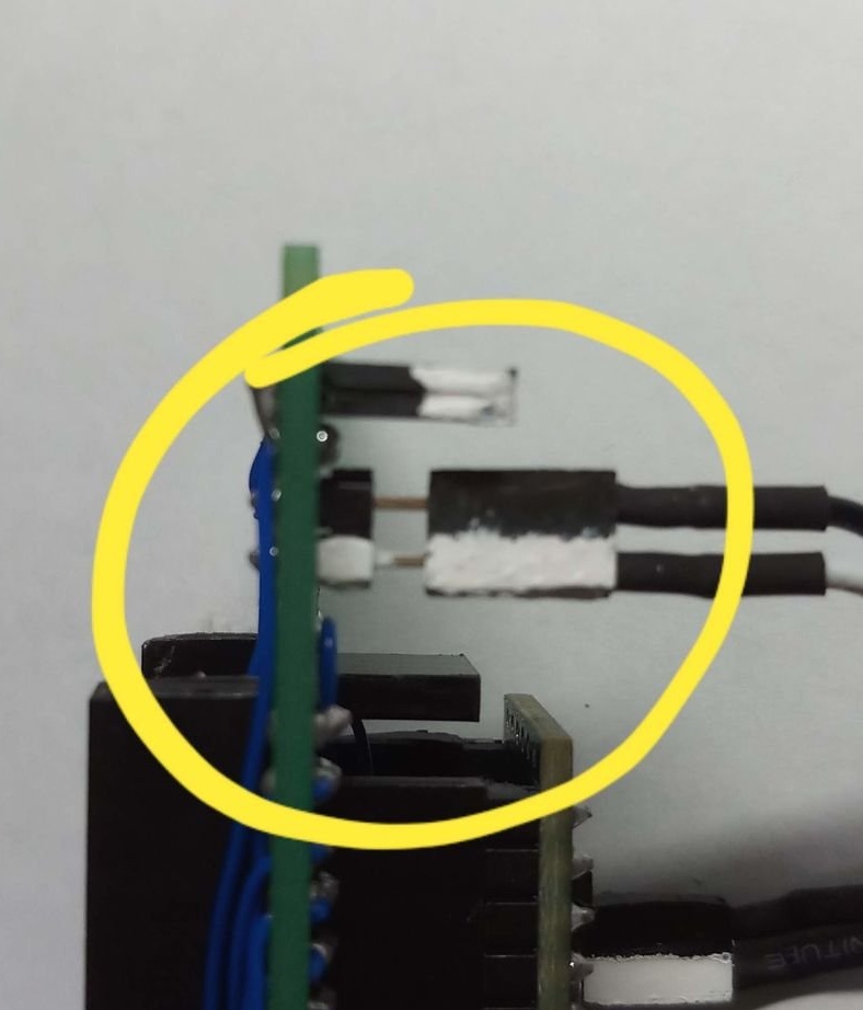
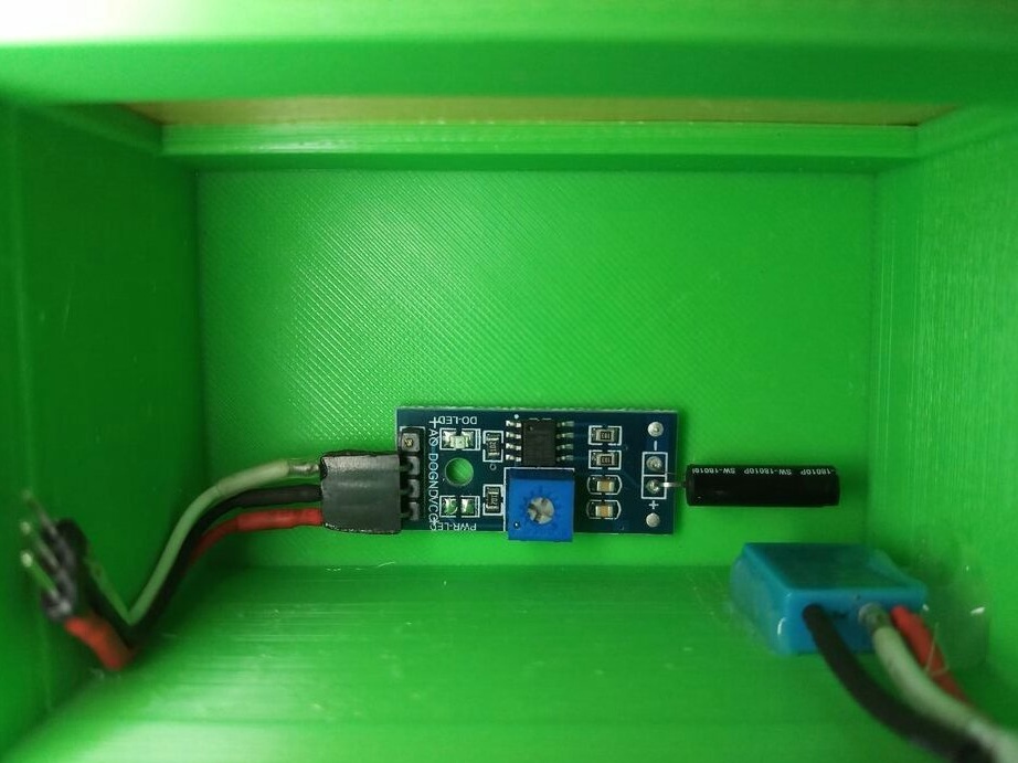
And so he has a vibration sensor:


The watch is ready:


So you can switch modes:


Note by the translator. The vibration sensor in this design provides only mode switching. You can set the time in the DS1307 module using the same Arduino, here told how.
9.6
9.7
9.9

Add a comment

    • smilesmilesxaxaokdontknowyahoonea
      bossscratchfoolyesyes-yesaggressivesecret
      sorrydancedance2dance3pardonhelpdrinks
      stopfriendsgoodgoodgoodwhistleswoontongue
      smokeclappingcraydeclarederisivedon-t_mentiondownload
      heatirefullaugh1mdameetingmoskingnegative
      not_ipopcornpunishreadscarescaressearch
      tauntthank_youthisto_clueumnikacuteagree
      badbeeeblack_eyeblum3blushboastboredom
      censoredpleasantrysecret2threatenvictoryyusun_bespectacled
      shokrespektlolprevedwelcomekrutoyya_za
      ya_dobryihelperne_huliganne_othodifludbanclose
1 a comment
Note: the drawn algorithm does not match the one shown in the video recording. Yes, and does not match the algorithm, because of the "Display Temp." 2 arrows come out.
Warning for those who want to repeat: in this circuit, an indicator with a common cathode is used, which allows a direct connection, not through a transistor Arduino to the conclusions of the digits of the indicator (D1-D4). But the lack of current-limiting resistors between the controller and the indicator segments cannot be recommended as normal.
Programmer and Arduino Pro Mini connection: indicated that the DTR of the programmer is to GRN on the board. On no Pro-series board did I have a contact labeled as GRN, and on all the required contact was labeled as DTR.
Well, the programmer is suitable for almost any one that supports DTR signals and, if possible, the voltage of the microcontroller (3.3 or 5 V).
Instead of the RTC DS1307, it is better to use the DS3231 - more precisely.
Instead of the indicator 8402AS (the height of the digits is 0.8 inches), you can use any suitable 7-segment with 4 digits with a common cathode (usually the letter A in the number): for example, 5463AX (the height of the digits is 0.56 inches), but you may need to change code due to different pinout indicators.
The program is also not without flaws, including in handling time. Call RTC Every Cycle - Why? Why shift the time by 25 minutes from the value in RTC? It is better to make a simple sketch of configuring RTC by command through the com port, configure it, and then flash the working code that does not contain attempts to initialize RTC.
And then add control button processing to set the clock. And then continue to develop the project.

But using vibration sensors is a curious move. A few years ago I made an alarm with such a sensor, turning off from shaking for a few seconds.

We advise you to read:

Hand it for the smartphone ...