
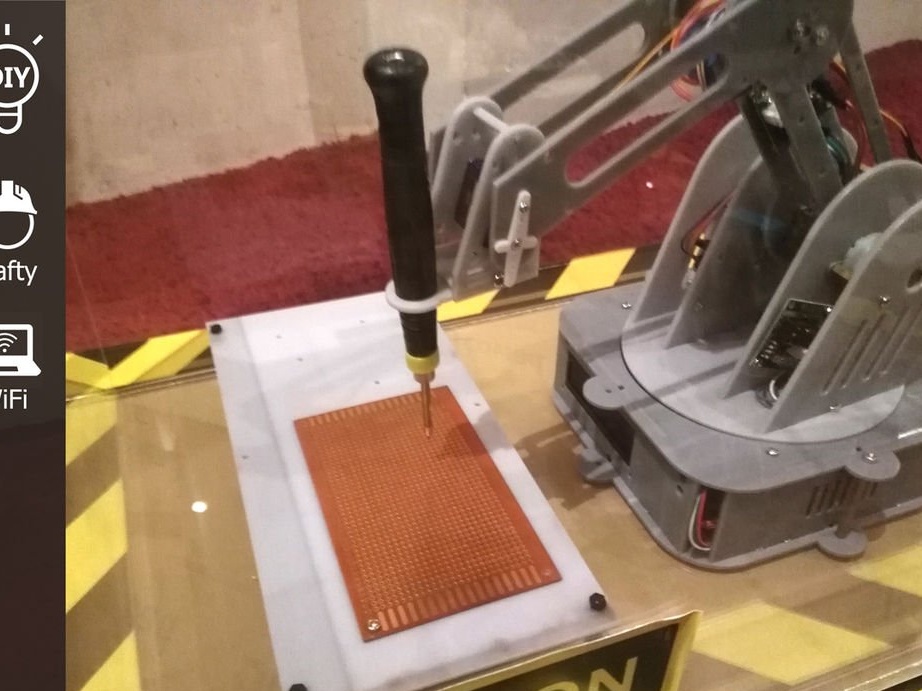

Unfortunately, this material will not pull on a full-fledged article, therefore, I decided to place it in the "tips", maybe someone may need the material. The article tells how to solder electronic components on a printed circuit board using an automated manipulator arm.
The idea of the project came to the master’s mind by chance when he studied various possibilities of robotic manipulators, and then discovered that there are several that cover the area of automated welding and soldering by a robotic manipulator.
Tools and materials:
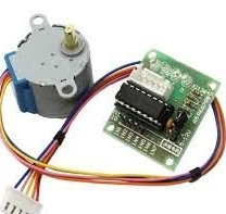
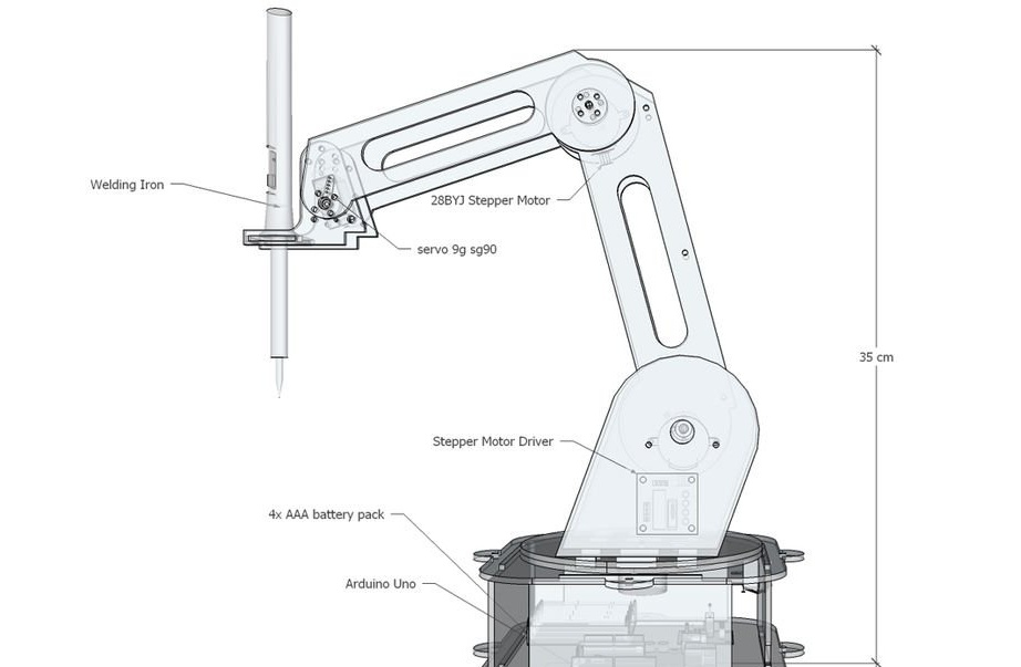
-Step motor 28BYJ-48 with driver module ULN2003;
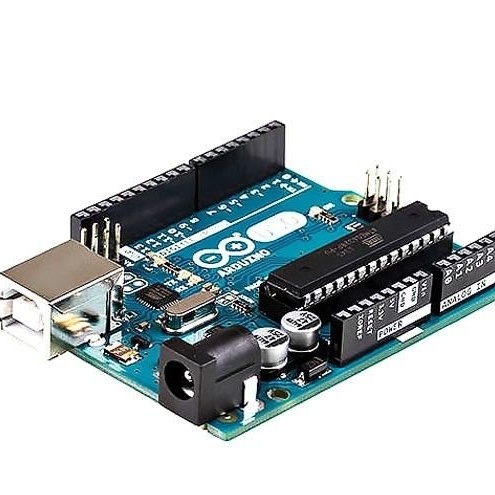
- Arduino Uno R3;
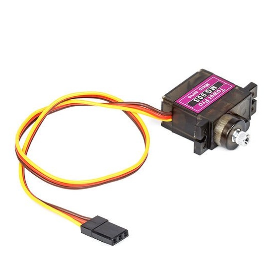
Servo-motor MG-90S;
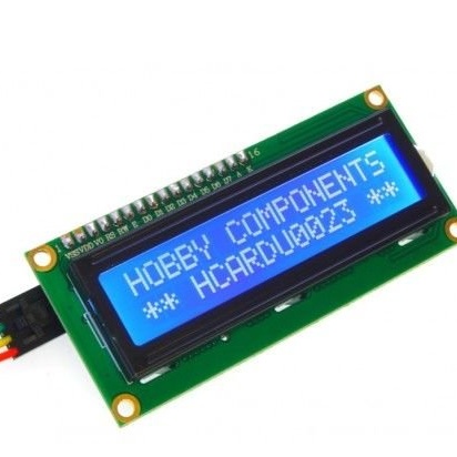
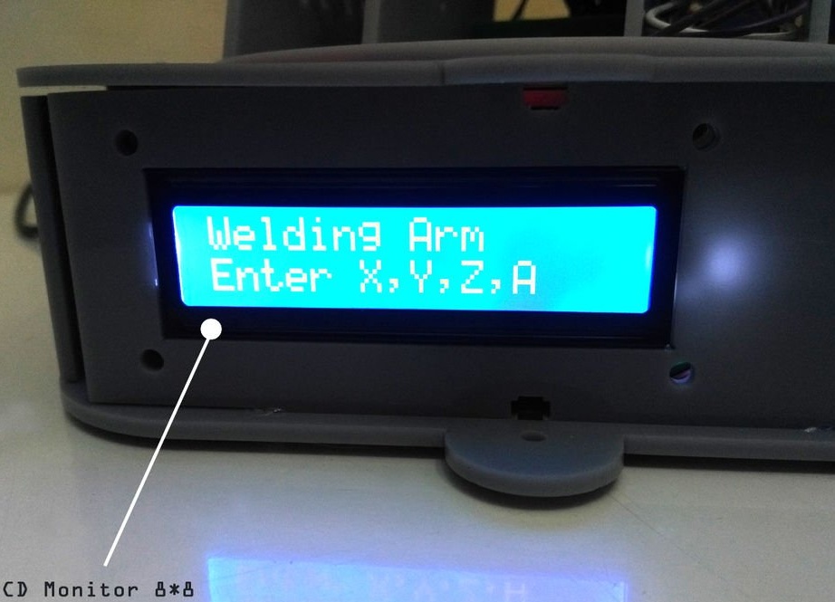
- LCD 1602;
-Bread board;
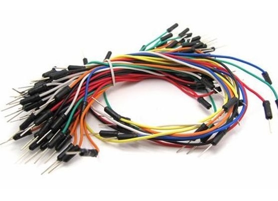
- connecting wires;
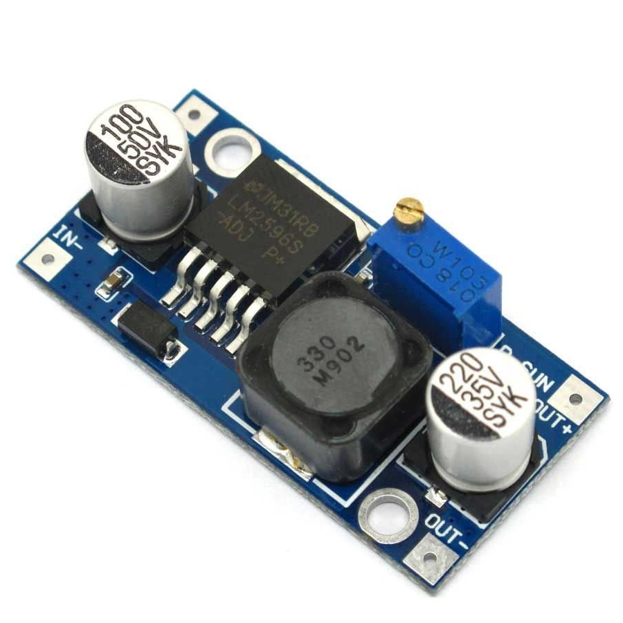
- Lowering converter;
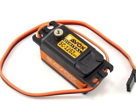
-Servox SC-1252MG $ Servo Drive
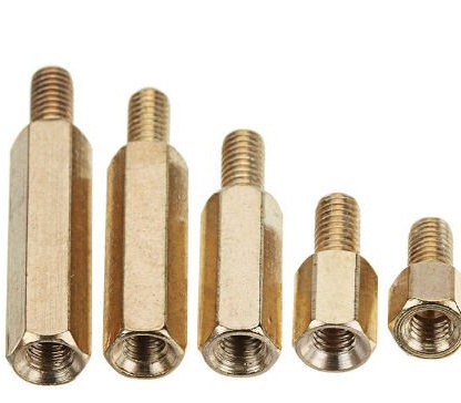
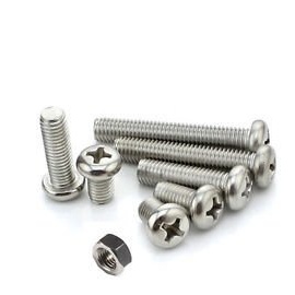
-Fasteners;
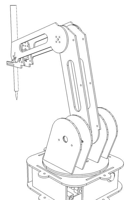
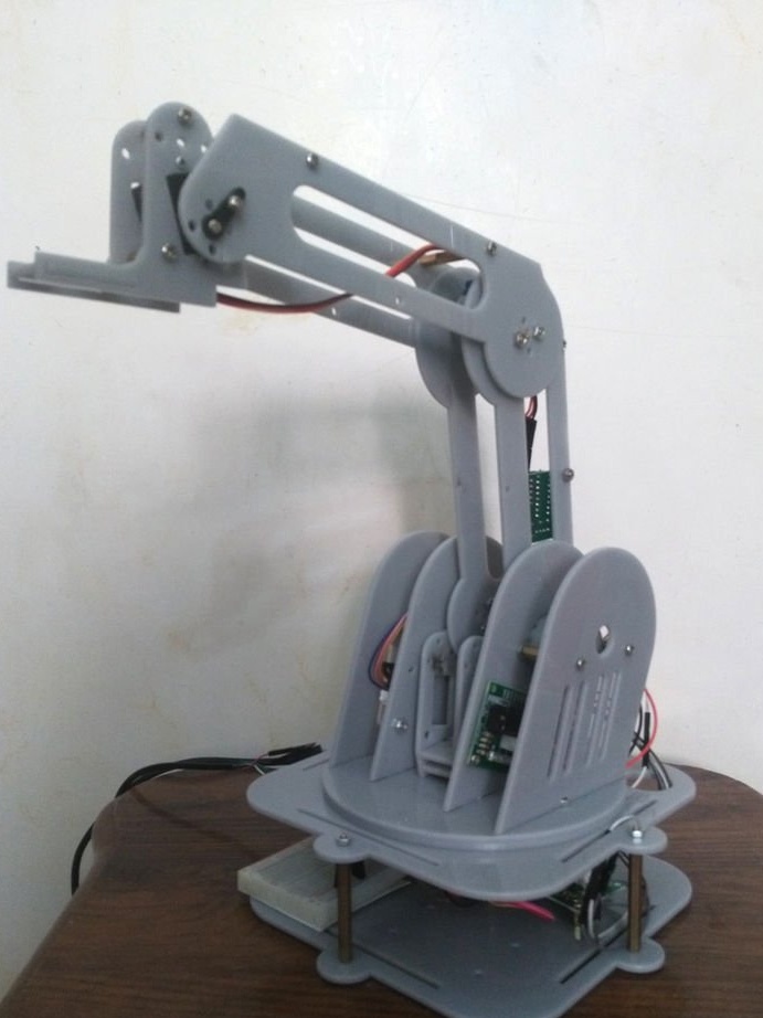
The wizard first developed the project. Part of the details was cut out on a CNC machine with a laser.
After assembling all the parts, a number of problems were revealed:
1. The levers were too heavy for small stepper motors to control.
2. Since model was made of plastic, the friction of the rotating base was high, and the movements were not smooth.
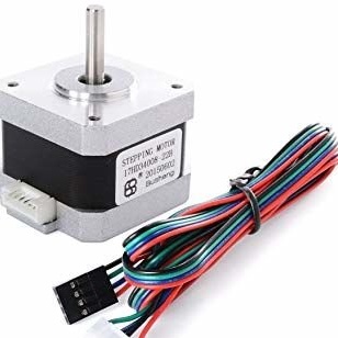
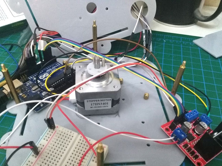
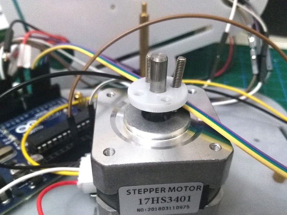
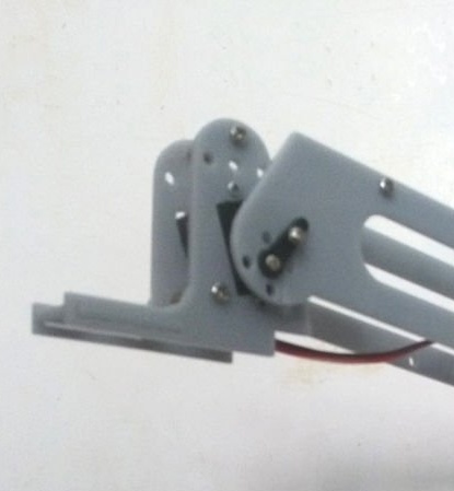
The first solution was to buy a larger stepper motor capable of withstanding weight and friction, and the master remade the base for installing a larger stepper motor.
But the problem did not disappear, and then the master completely changed the basic design and installed a servomotor with a gearbox and metal gears.
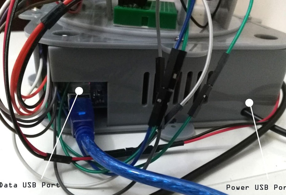
3. The voltage.
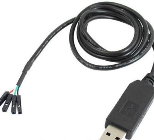
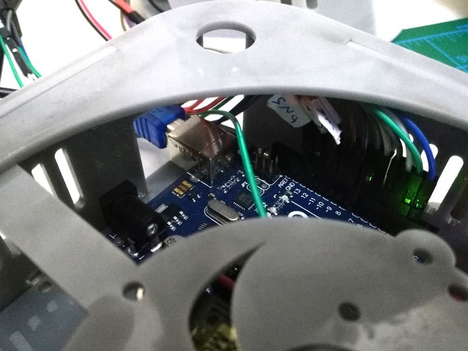
The Arduino can be powered either from the DC power connector (7-12 V), the USB connector (5 V), or from the VIN pin of the board (7-12 V). The voltage supply through the 5 V or 3.3 V contacts bypasses the regulator, and the master decided to buy a special USB cable that supports 5 V from a PC or any power source.
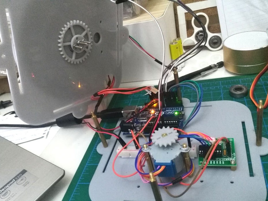
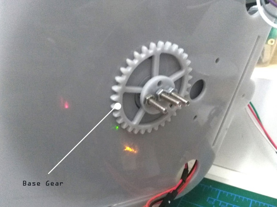
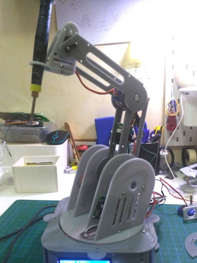
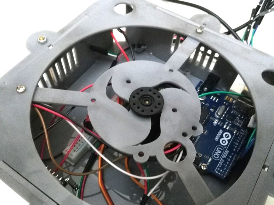
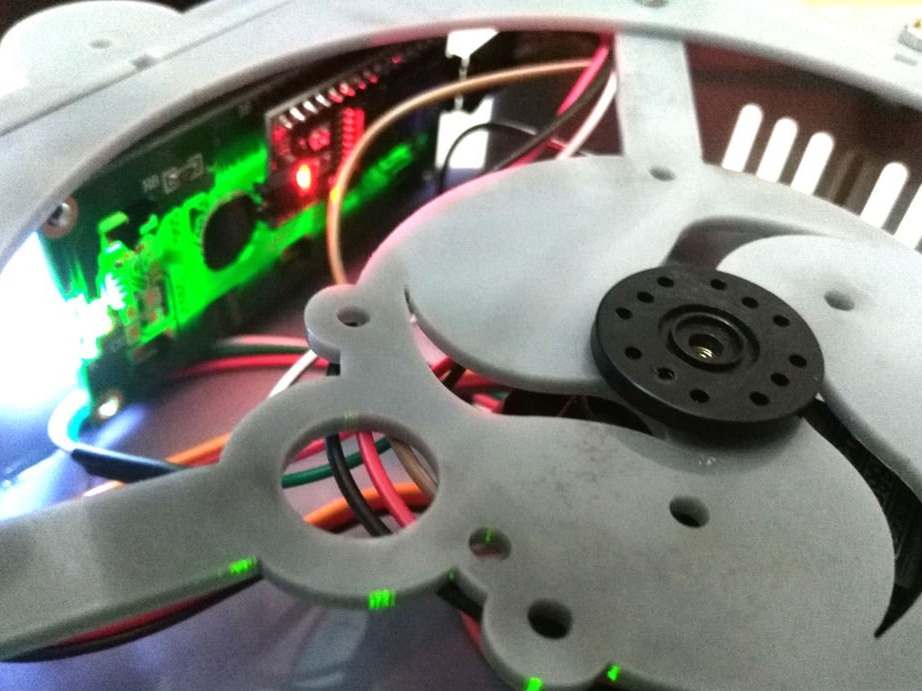
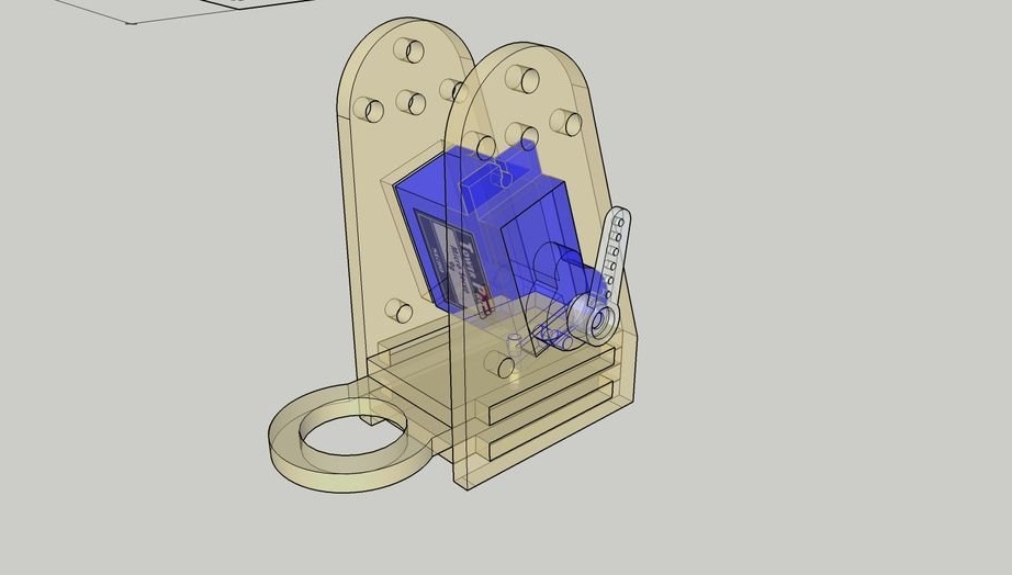
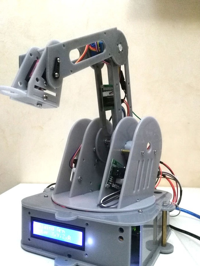
After some modifications, the master changed the design of the model, reducing the size of the brackets and making a suitable hole for the servo motor gearbox, as shown in the photo.
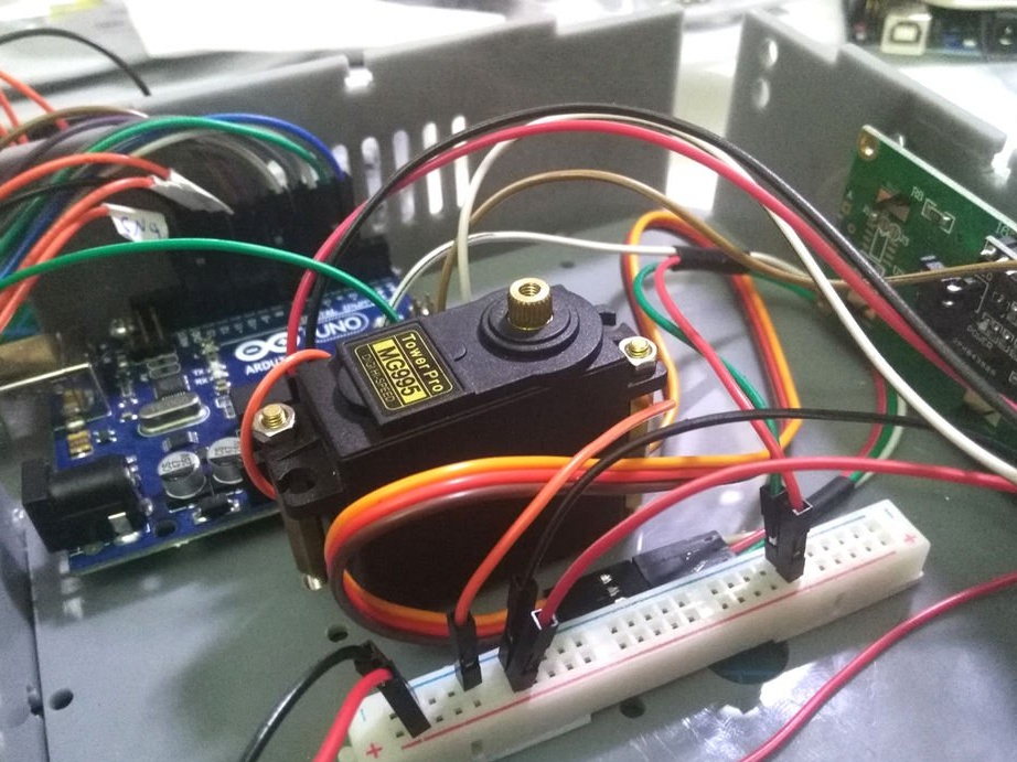
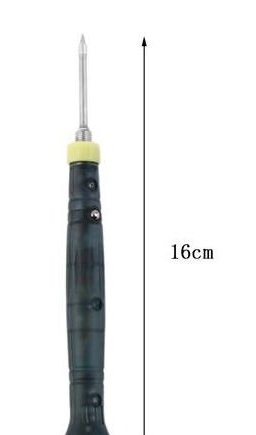
To hold the soldering iron, the master made a special mount.For proper operation, a servomotor is needed with a 180 degree rotation parameter.
The code can be downloaded below.
ProjectCodeFirst.ino
Highlights of the manufacture of the device can be seen in the video.
Of course, information is not enough, there is no diagram, there are no files for the CNC, there are no examples of the device’s operation, but there is a good idea and perhaps an interested wizard, on the basis of this idea he will make a fully functional device.