

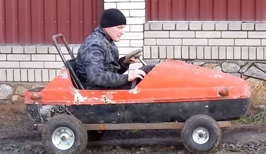
Hello friends! Today I want to tell you how I realized my childhood dream. In childhood, probably, like most boys, I dreamed of my own childhood caron which it would be possible to move independently. I wanted a machine with a motor.
My brother and I had a pedal car, but that was not at all what, and of course I wanted more. In the 90s I was a teenager and it was less problematic to get any spare parts - engine, wheels and other parts. When I grew up, I got a hobby - designing and manufacturing all kinds of equipment and other homemade, just then it came to my mind to realize my childhood dream.
I really wanted to make a small machine, but one so that I could easily fit in it.
I had a stroller from an old Java motorcycle, and I decided that I would use it as a body that would be attached to the frame. Now, having decided on the concept of my car, I began to collect all the spare parts in a heap.
Materials and components
1. The engine from the Ural chainsaw
2. Gearbox from the motorcycle M-72
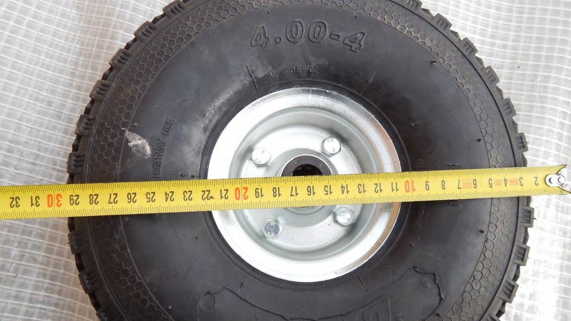
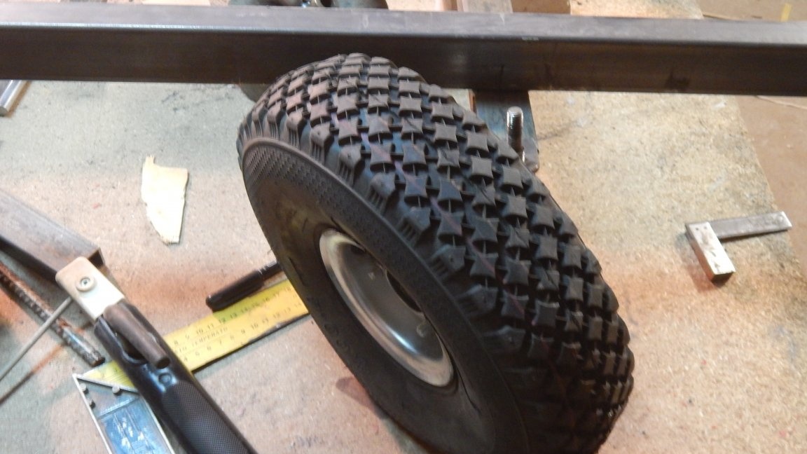
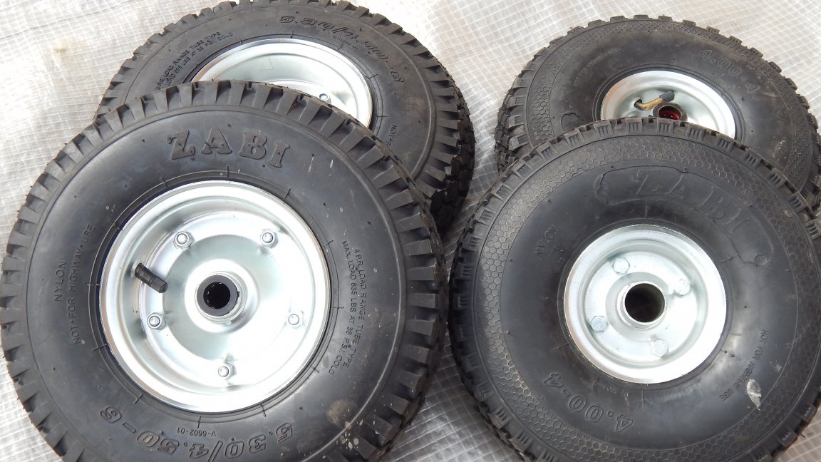
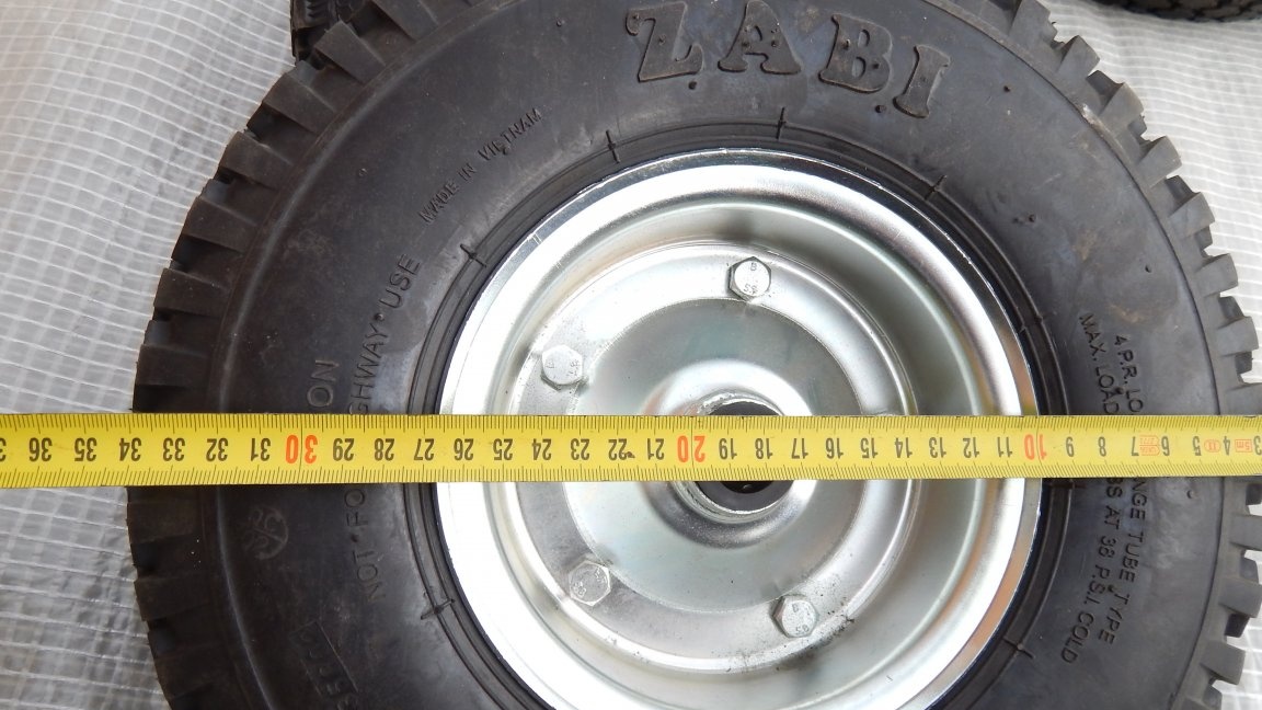
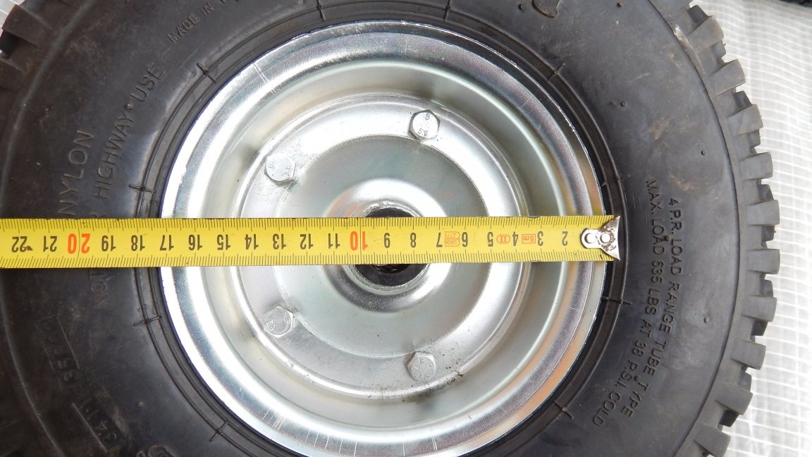
3. Wheels from a garden car - front 4 inches (300 mm on the outside), rear 6 inches (350 mm on the outside)
4. Rear axle 30 mm thickness, 900 mm length
5. Housing bearings UCP206 2 pcs. for rear axle
6. Profile pipe 50X30x2 mm for the frame
7. Steering wheel
8. Tank from the Ural chainsaw
Tool and consumables
1. Bulgarian
2. Cutting off grinding wheels
3. Welding machine and electrodes
4. Drill
5. Set of drills
6. Round and flat file
7. Rivet gun with rivets
Start
Many who want to do something like this do not always understand where to start, and such a project comes to a standstill at an early stage of creation. In order for you to succeed and not have any problems, first think about how your car or other homemade product should end up. Then you need to assemble all the components that you need for assembly, and you can start manufacturing, and I will try to help you with this and tell you how I did it in stages.
Video instruction!
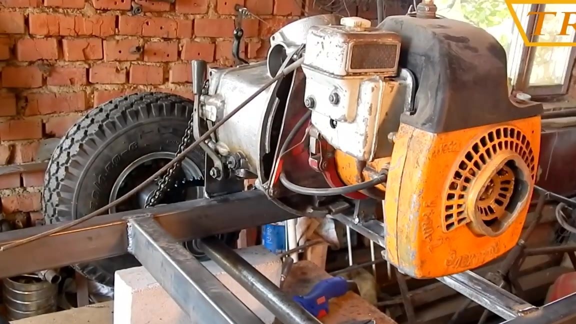
Step one: engine selection
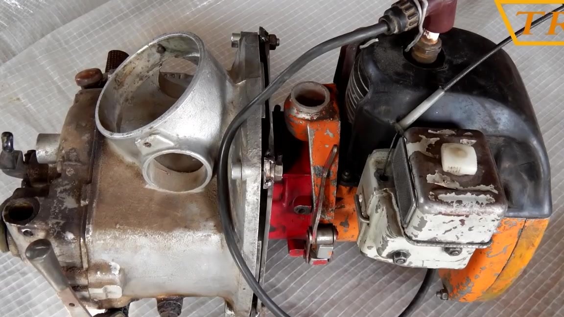
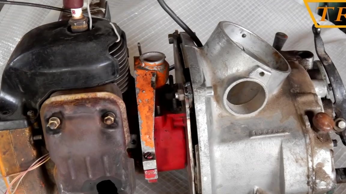
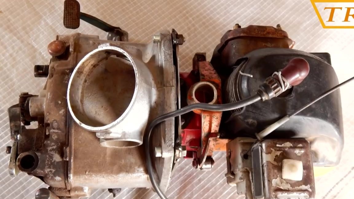
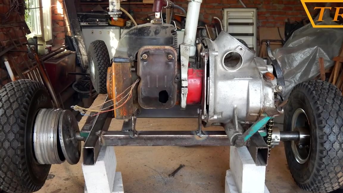
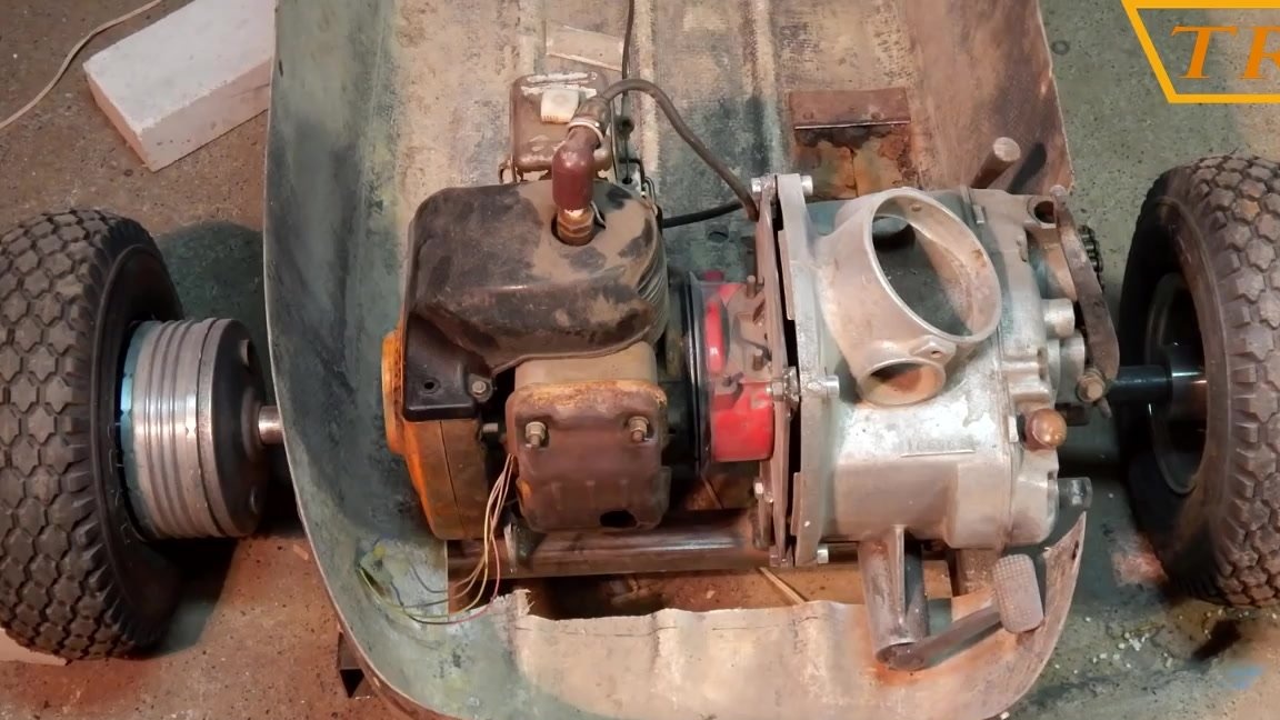
I started creating my car with the selection of the engine is not accidental. I had a stroller from a motorcycle and I wanted to install the engine so that it was hidden behind the body of the stroller.I also really wanted the machine to look like a real car, have a gearbox (gearbox) and reverse. As the engine, I decided to use the engine from the Ural chainsaw, it is compact, powerful (5 hp), has forced cooling and centrifugal clutch which was not superfluous for me. I took the checkpoint from a heavy motorcycle M-72 or Dnepr, MT-10, etc. The box has 4 gears and one reverse.
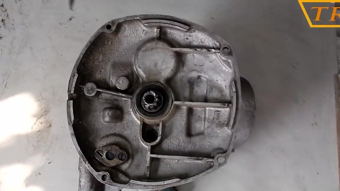
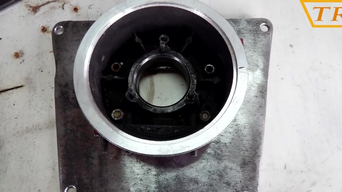
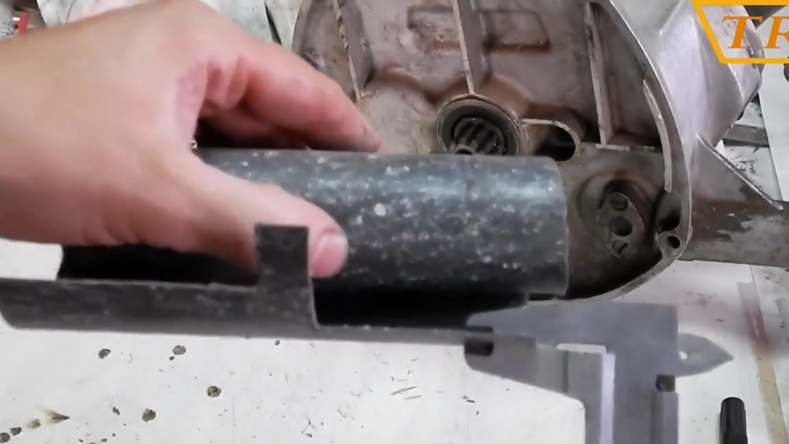
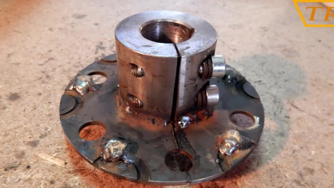
In order to connect the engine and gearbox, I took half of the crankcase (on the gearbox side) of the engine, and made a groove in it under the protrusion on the crankcase so that it fits tightly with the engine.
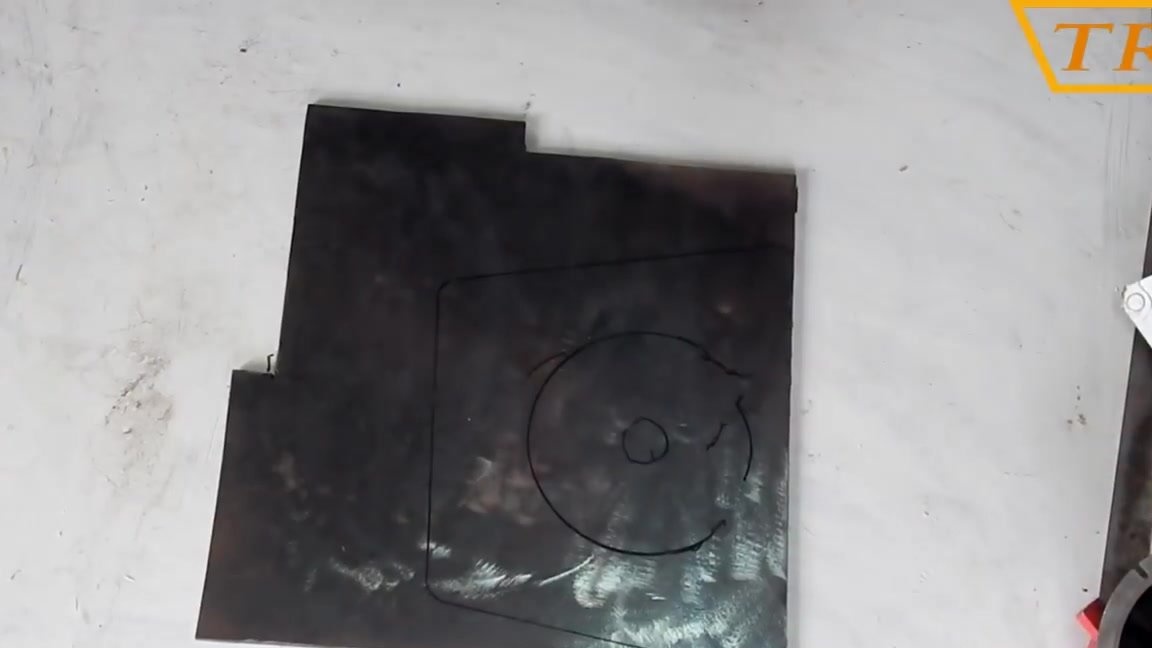
Then we take the checkpoint, and cut out the template along the contour of the cardboard box. In the template, we outline the holes through which the box fits into the engine, and cut out the template.
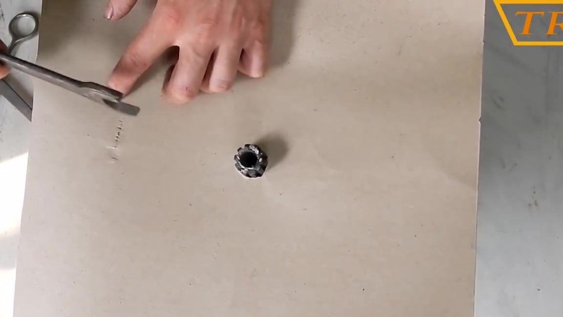
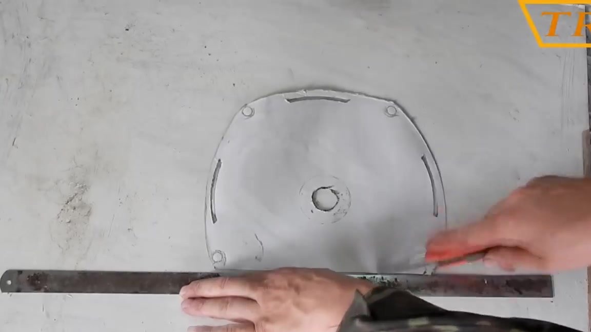
Now put the template on a piece of metal 5 mm and circle it marking all the holes. Next, we cut the metal along the marked outline, and drill holes.
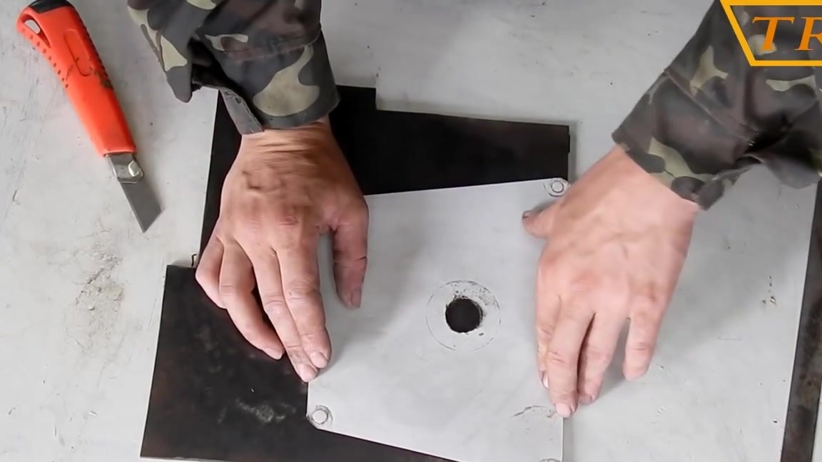
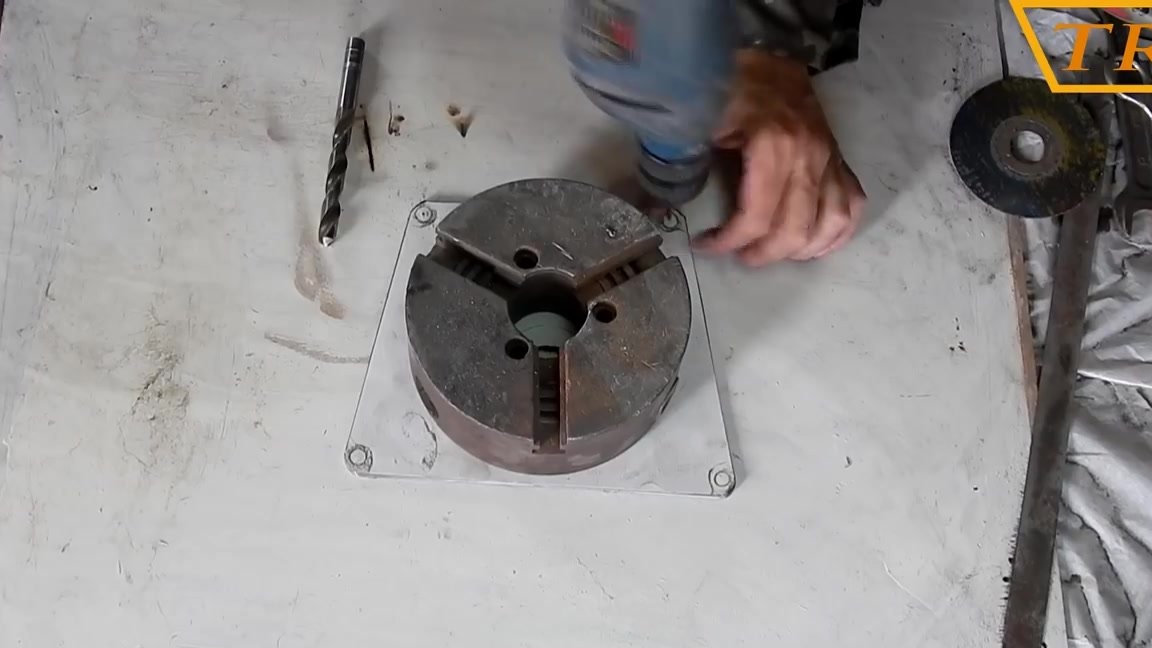
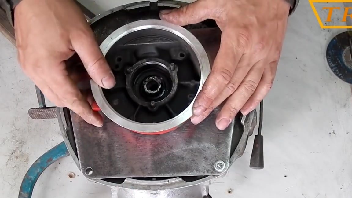
We fasten the plate to the box.
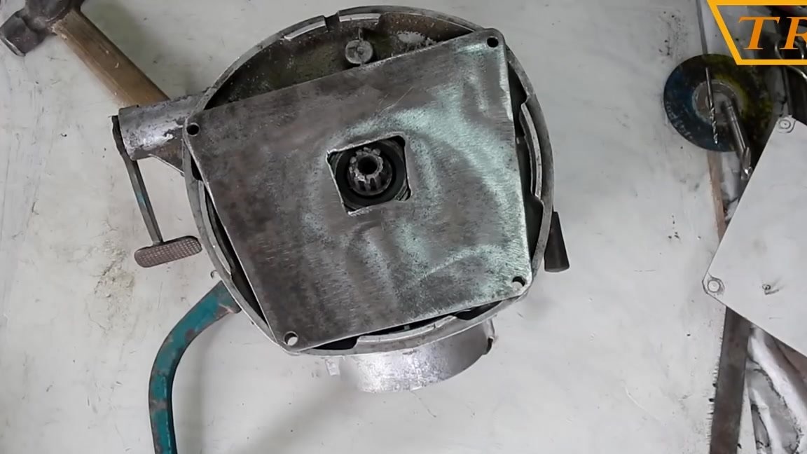
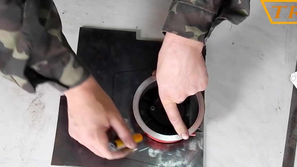
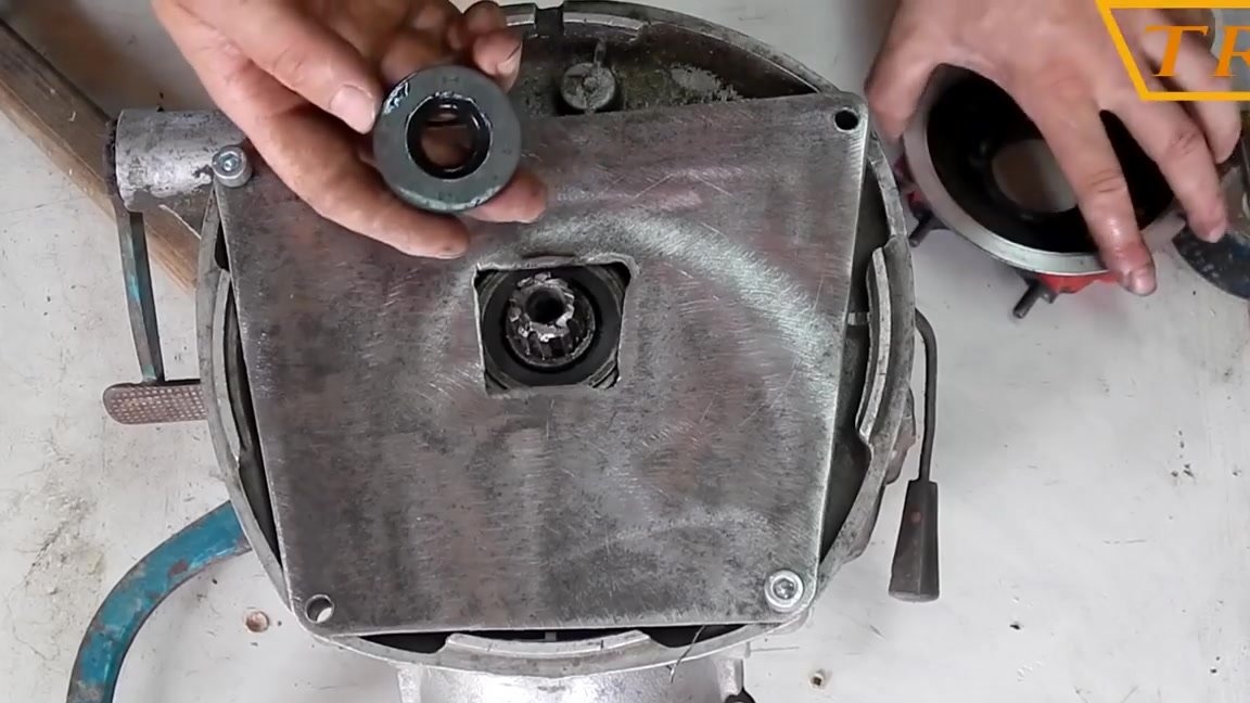
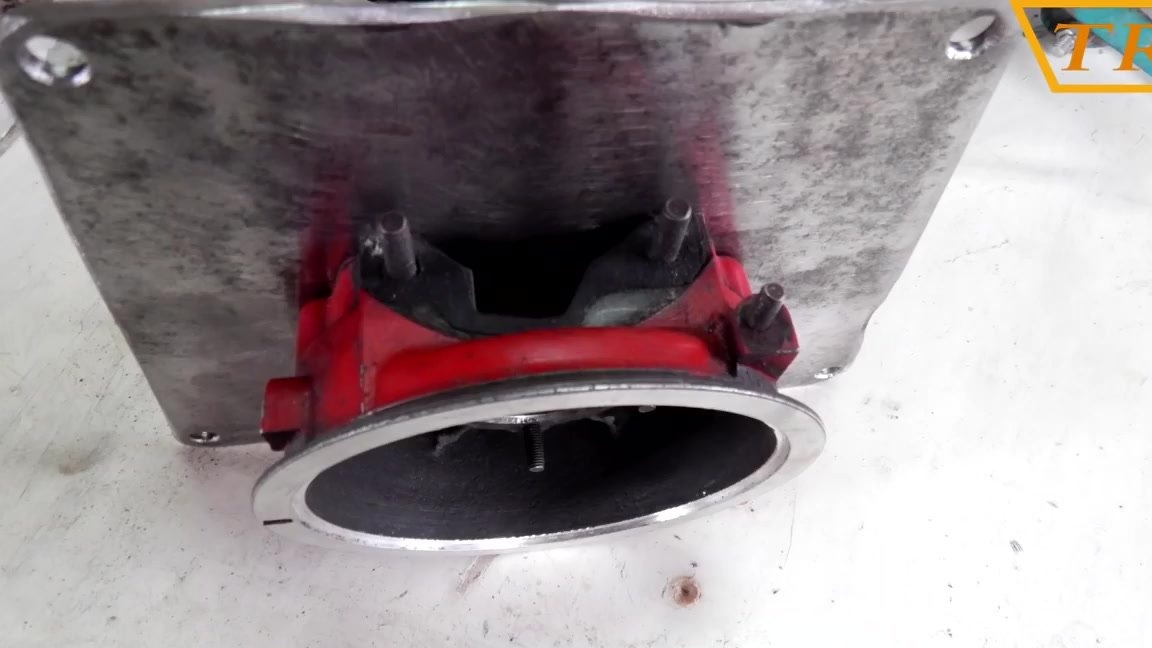
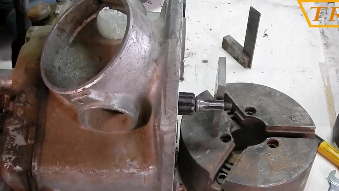
Now we select an oil seal with an outer diameter for the hole in the crankcase, and an inner one for the diameter of the input shaft of the box. We dress the oil seal on the shaft and set the crankcase on it.
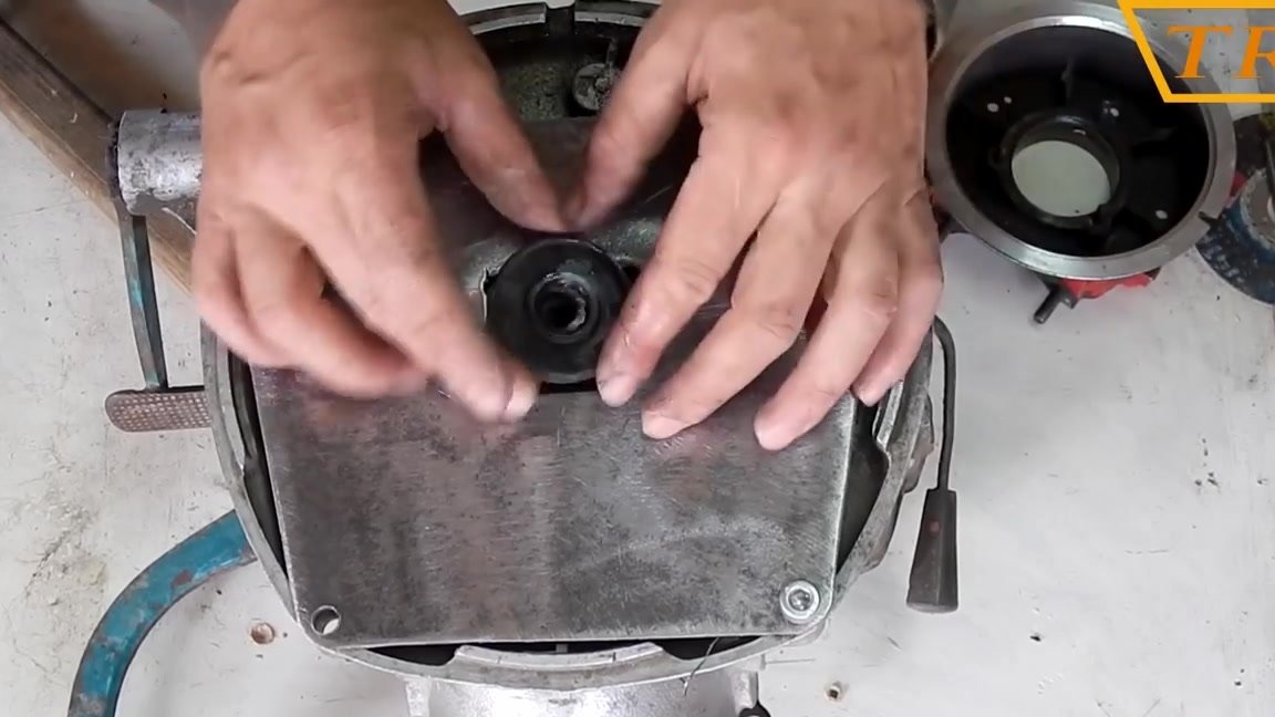
We transfer the crankcase holes to the plate, drill it under the diameter of the bolts and connect the plate to the crankcase with bolts.
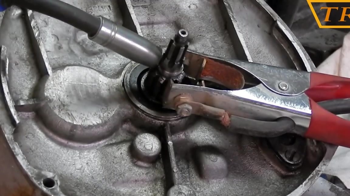
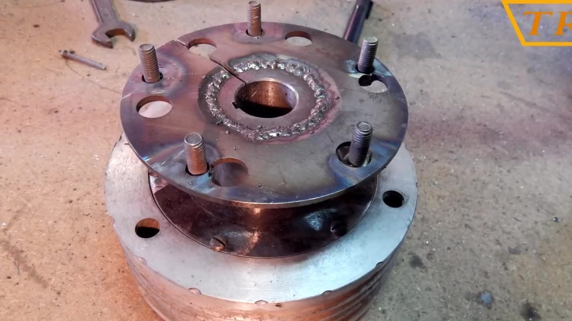
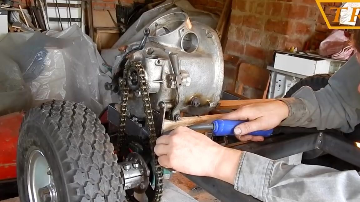
Next, you need to disassemble the chainsaw gear and pull out from there the shaft on which the clutch cup is mounted. Cut the shaft along the gear.
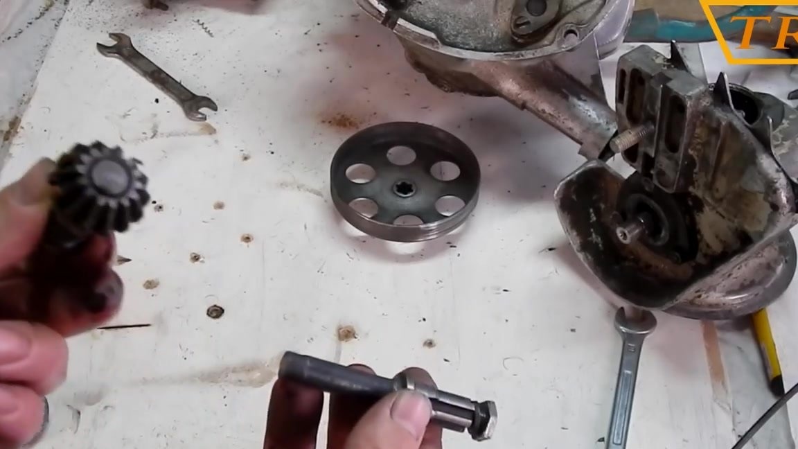
This piece of shaft must be welded to the input shaft of the gearbox. In order to set everything straight, I cut a piece of paronite 1 mm thick and insert it into the middle of the box shaft, and the shaft from the gearbox into it.
After checking the alignment I scald the shaft around the perimeter.
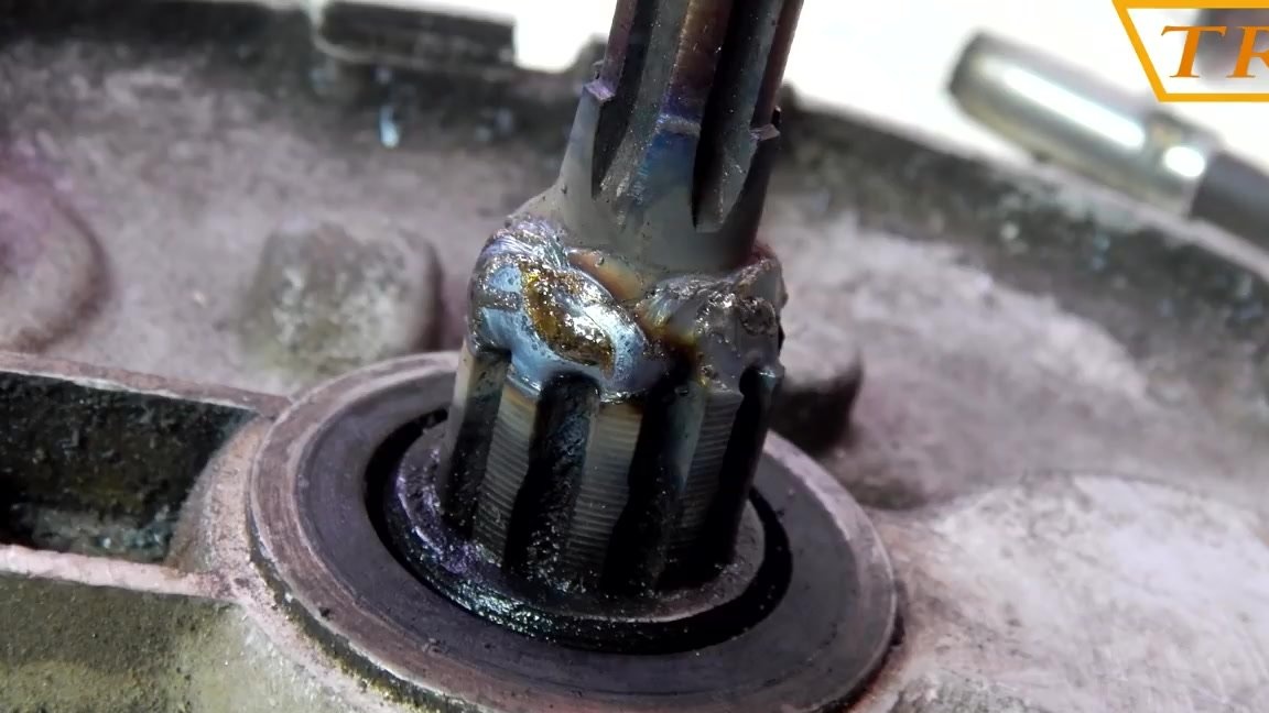
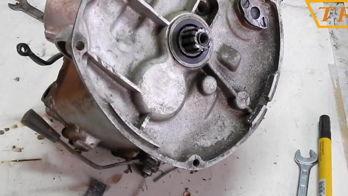
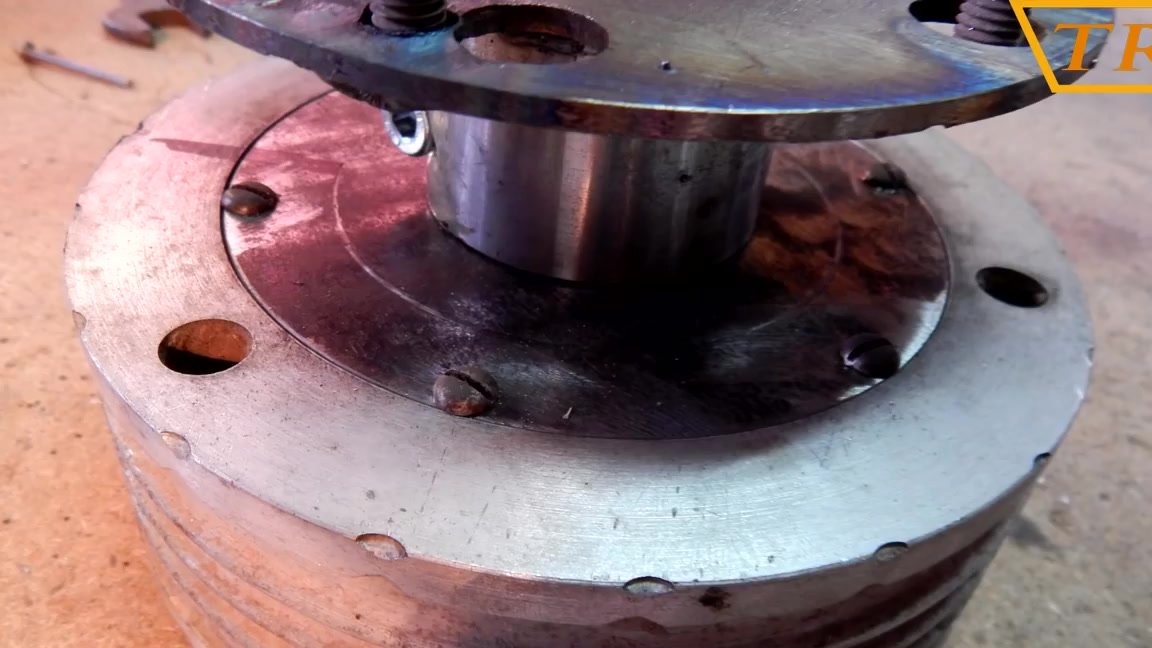
We fasten the plate with the crankcase to the gearbox, and put the clutch plate on the shaft clamping it with a nut.
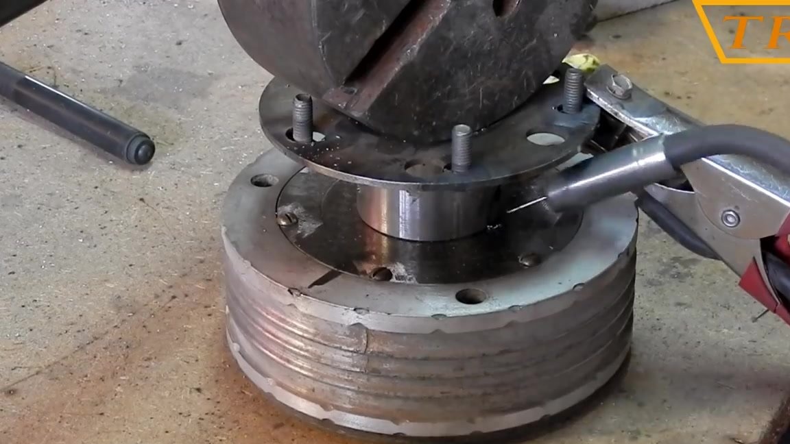
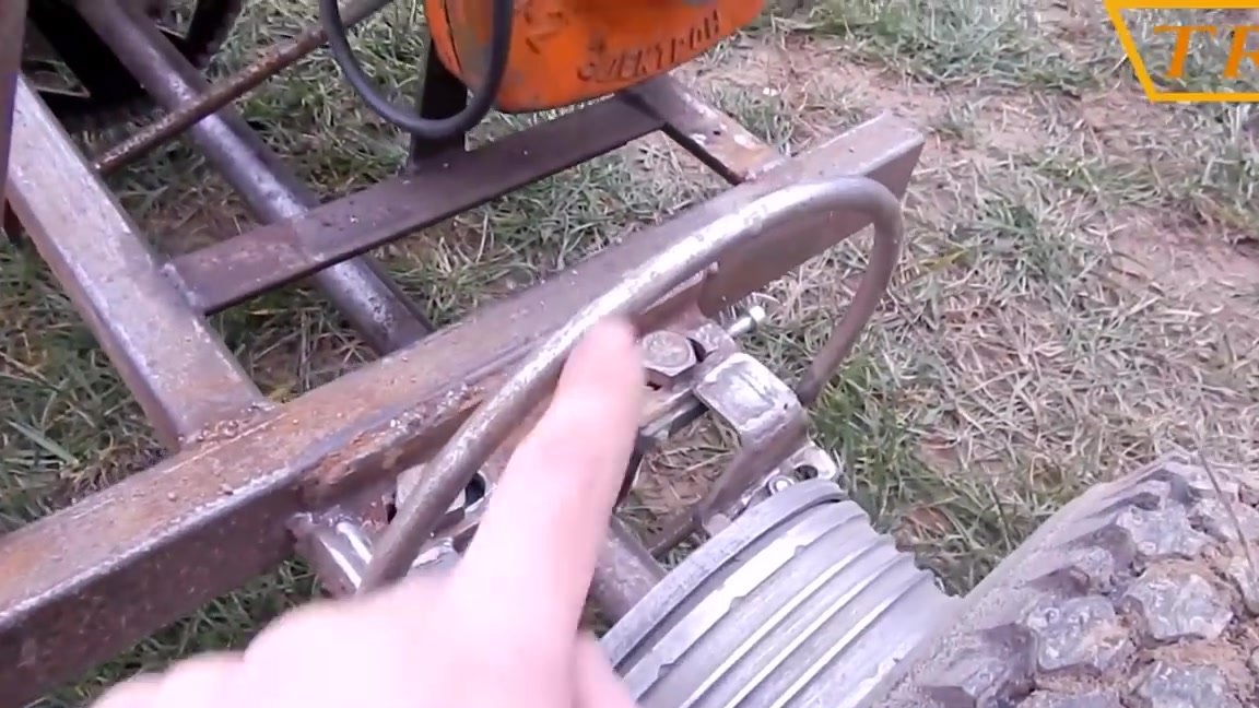
To connect the box to the engine, I cut the clamp from the steering wheel and connect the engine and gearbox with it.
Video instruction!
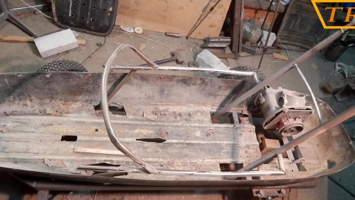
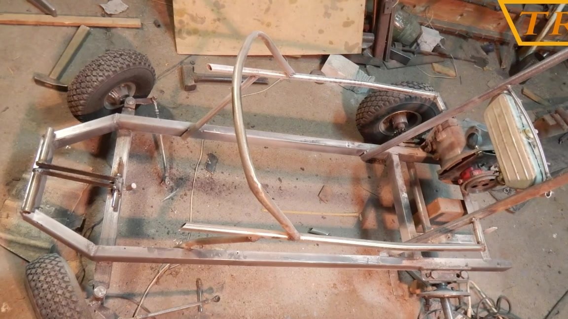
Step Two: Frame Making
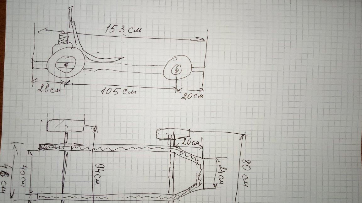
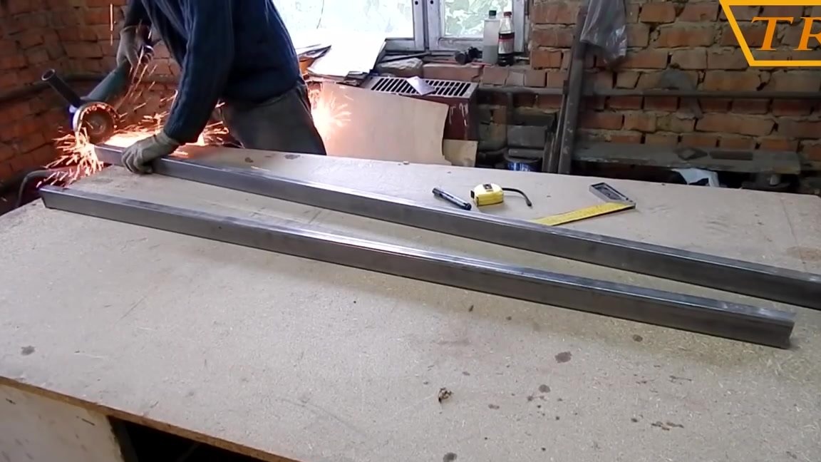
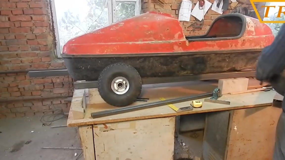
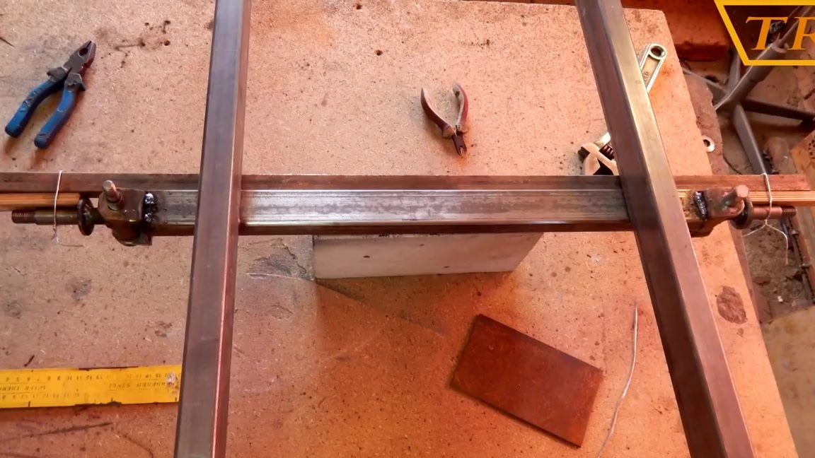
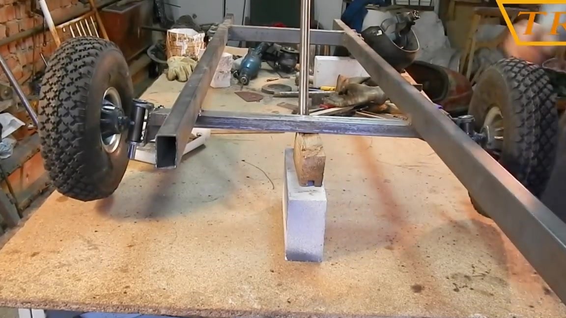
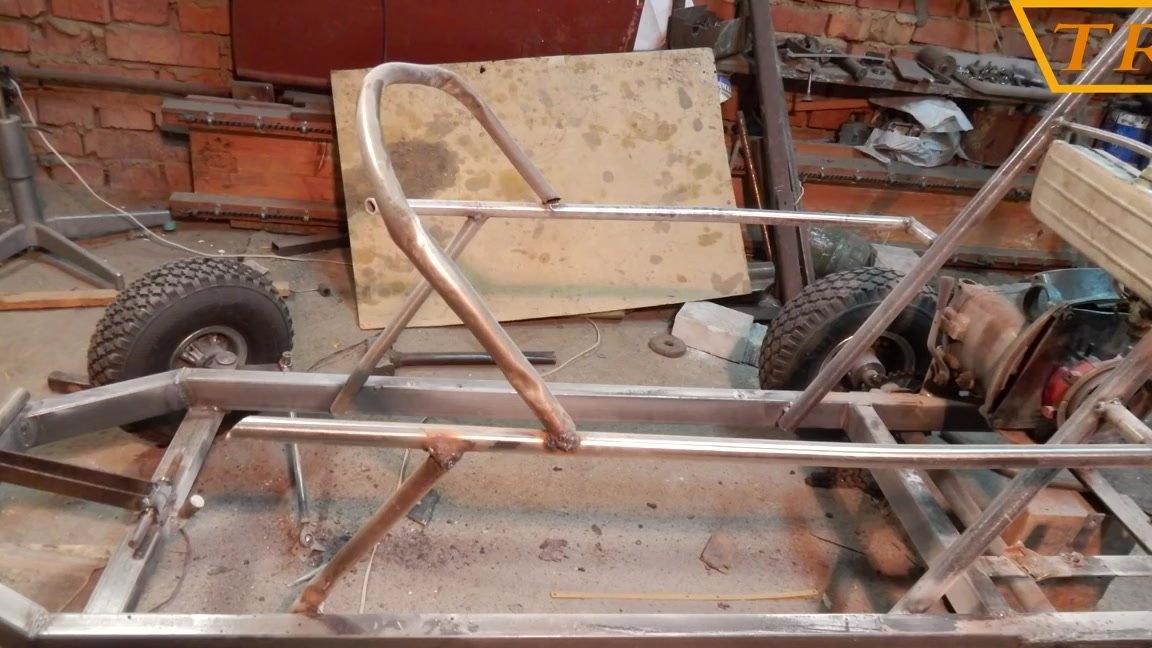
Now let's make the frame. For the frame, I bought a profile pipe 50x30x2 mm. I adjusted the length of the frame under the stroller so that it did not protrude much. To make it easier for you to know where the dimensions are, I made a drawing.
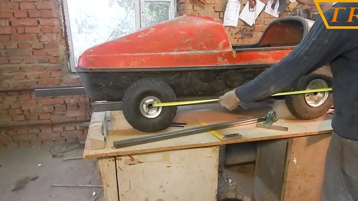
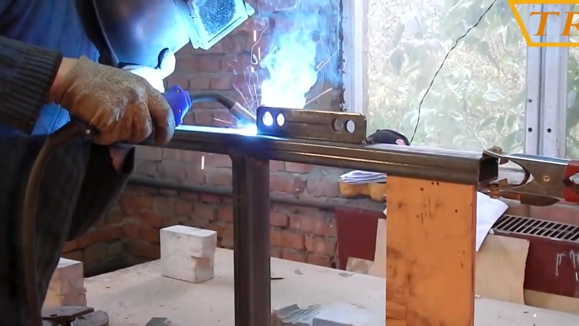
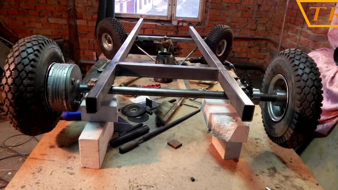
Rama cooked on a flat table but put everything on bricks so that it was possible to try on wheels, and it was convenient to cook from all sides.
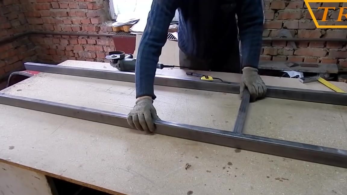
After connecting the two pieces of the frame across each other, trying on a stroller, exposing the wheels and putting marks on the frame where the wheels will be mounted.
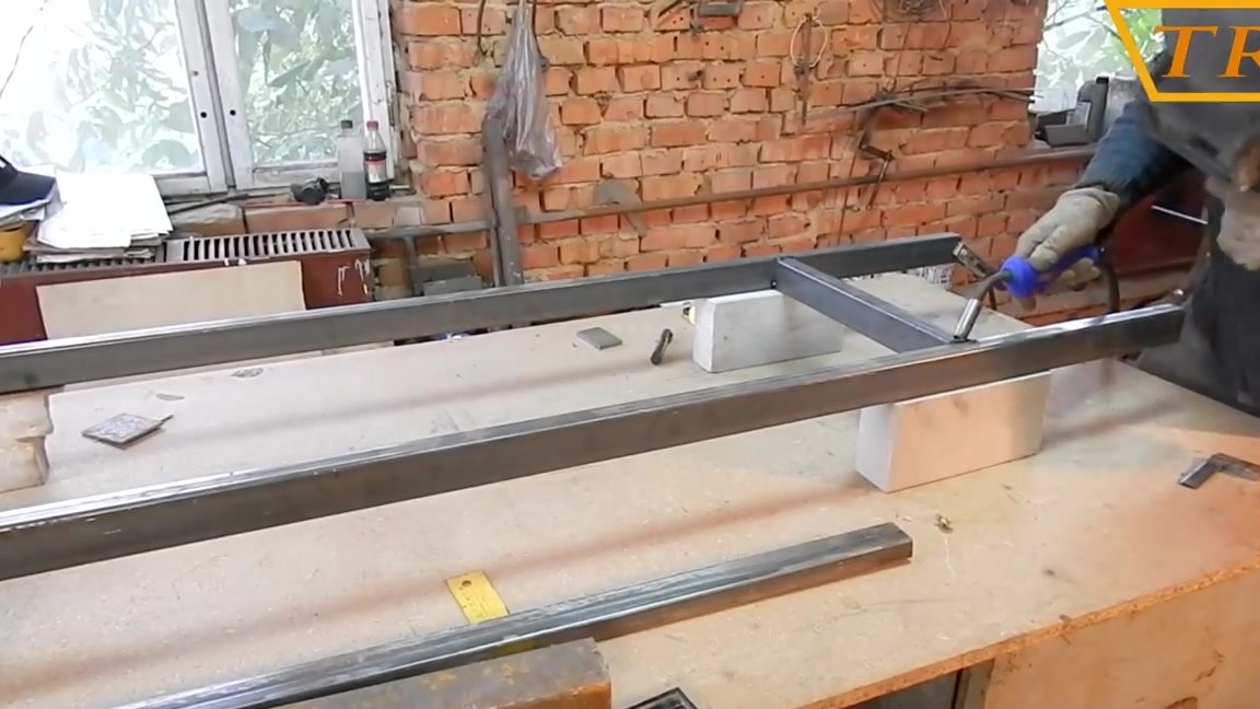
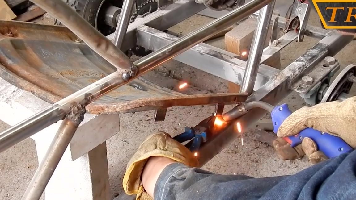
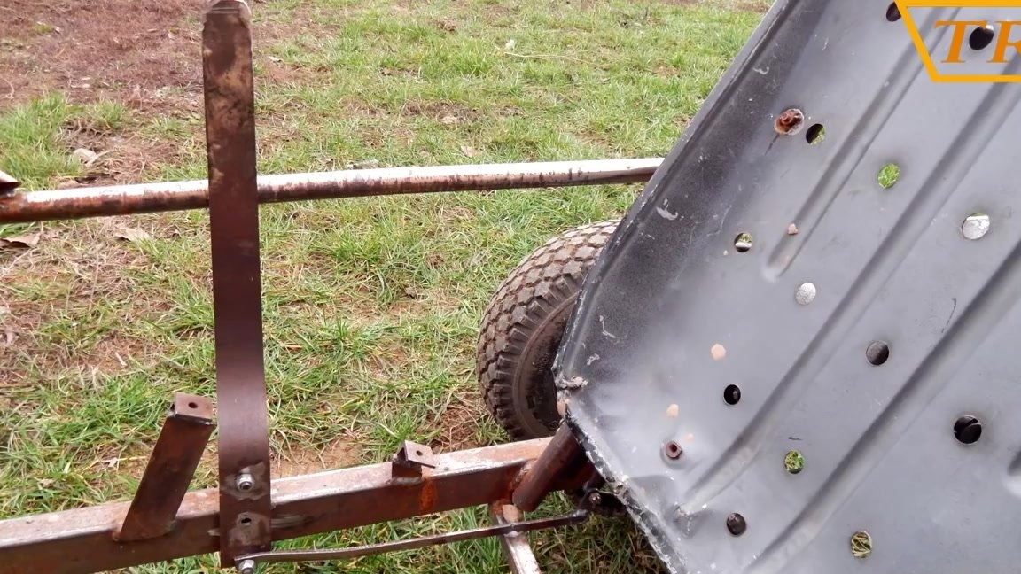
In front, for mounting the wheels to the frame, I weld a piece of a profile pipe 40x25x2 mm.
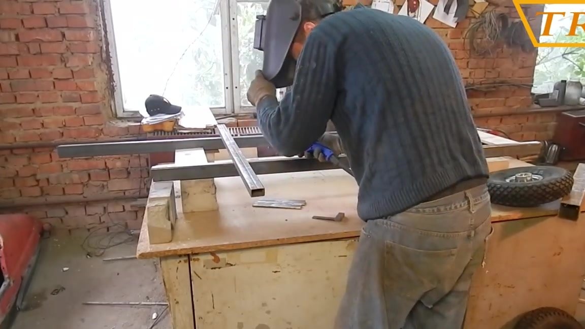
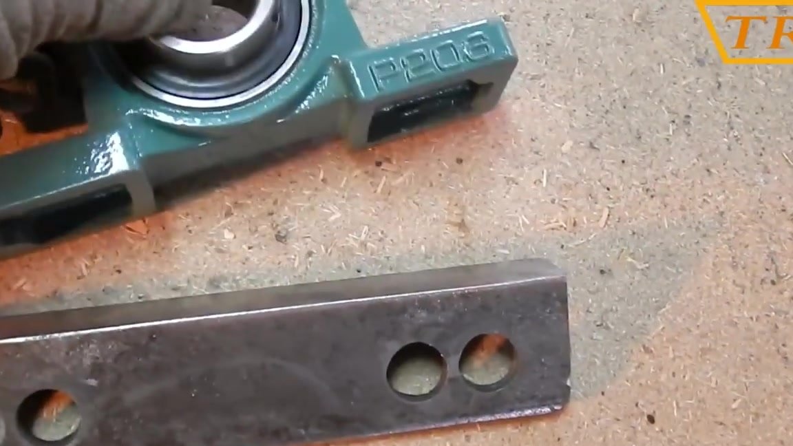
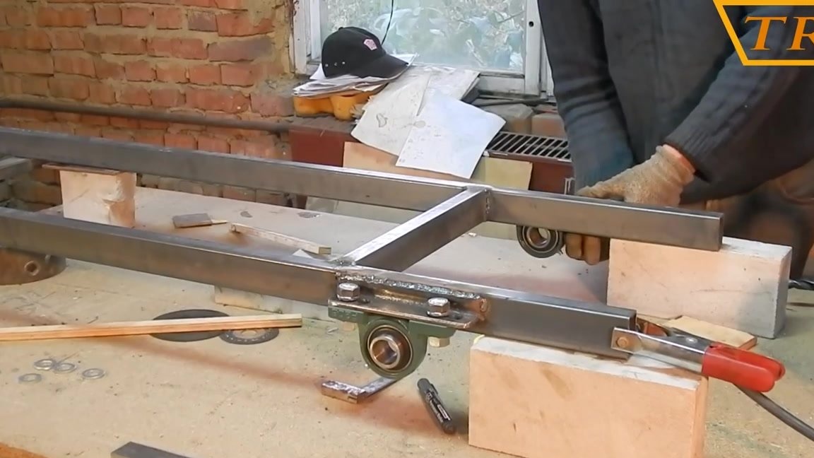
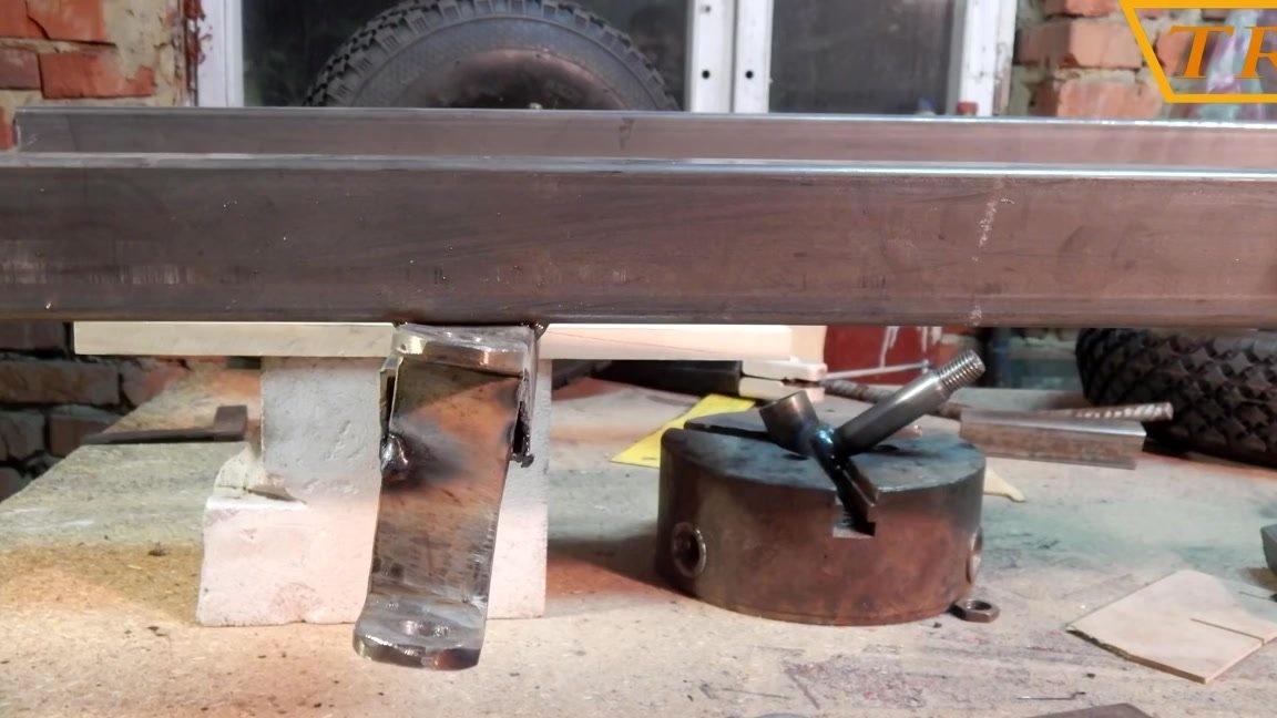
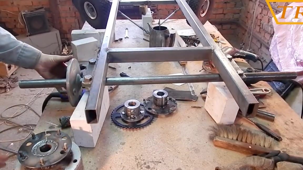
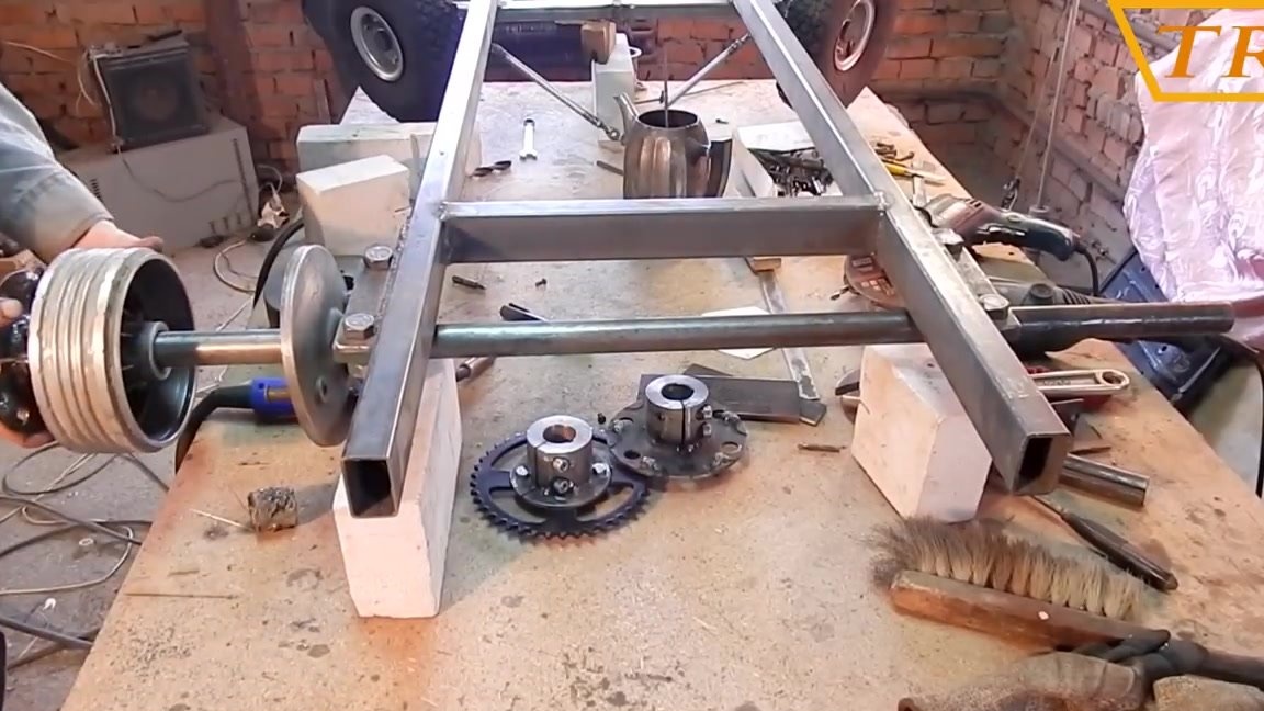
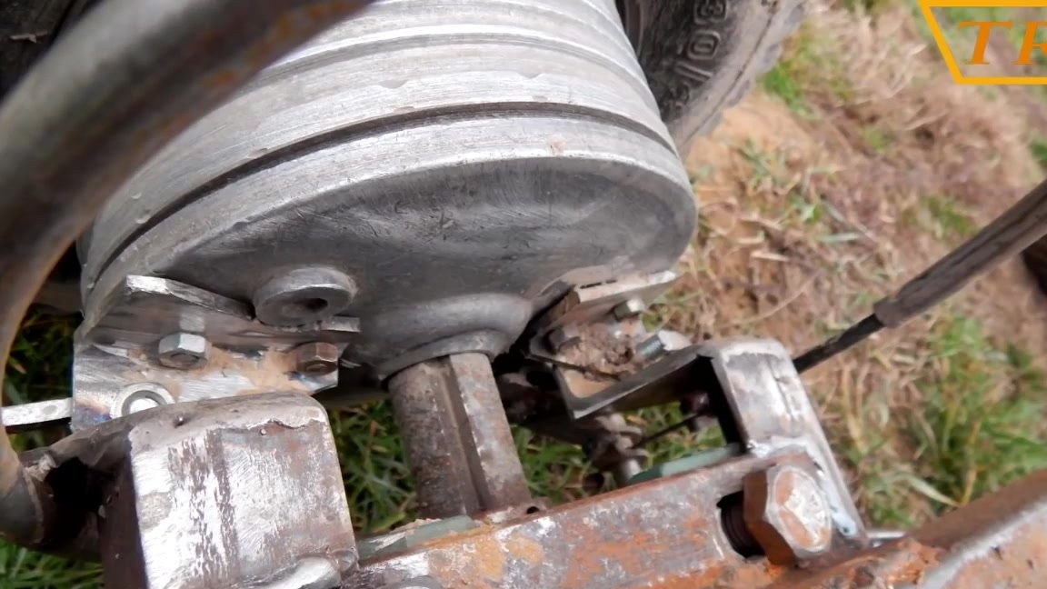
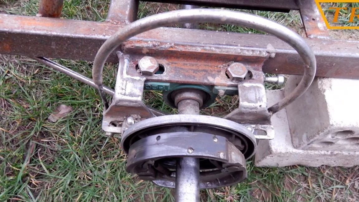
From a corner of 40x440 mm, I cut out the mount for the rear axle bearings, and drill holes for bolts in it. UCP206 housing bearings for the rear axle with a diameter of 30 mm.
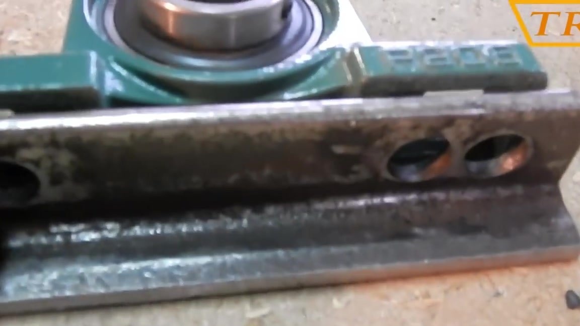
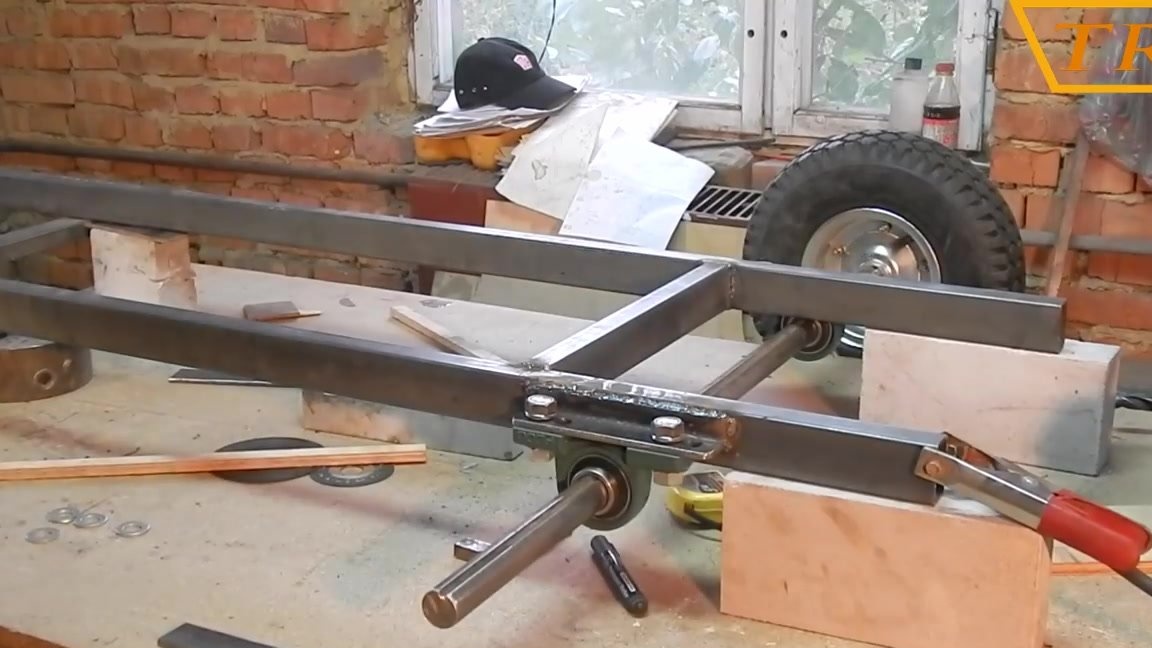
I weld the corners to the frame, fasten the housings to them and insert the axle with wheels into the bearings.
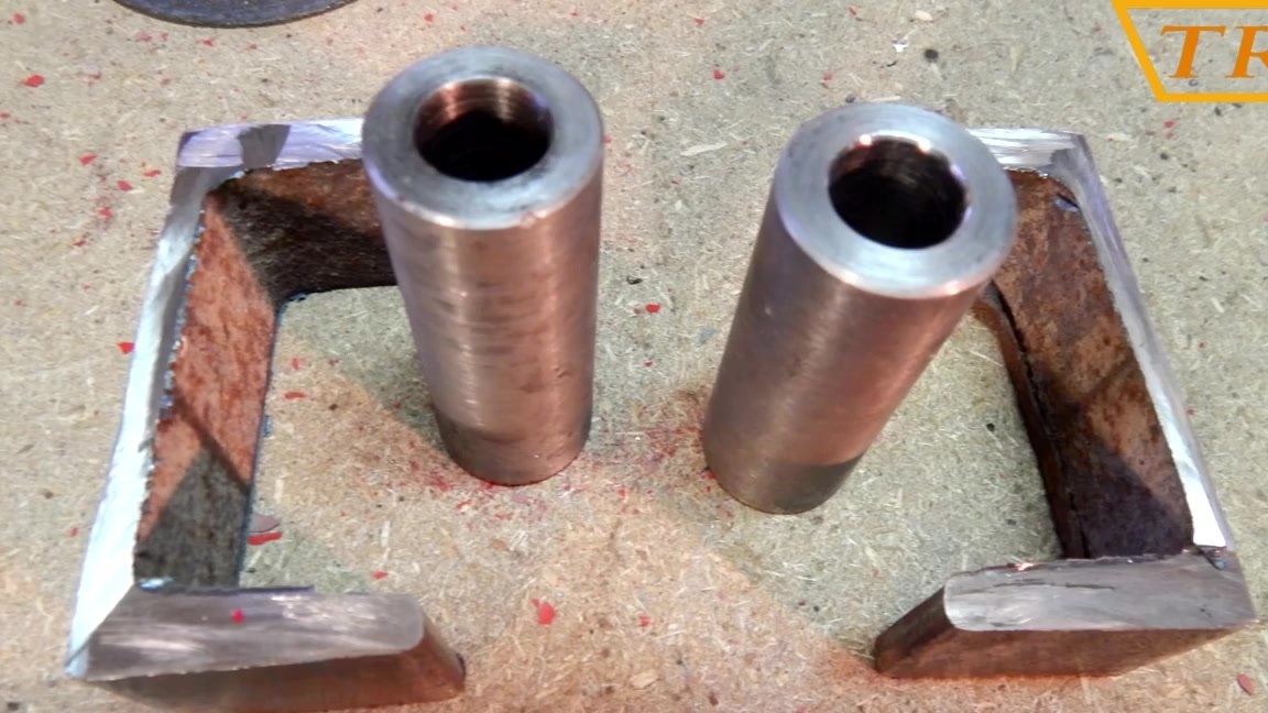
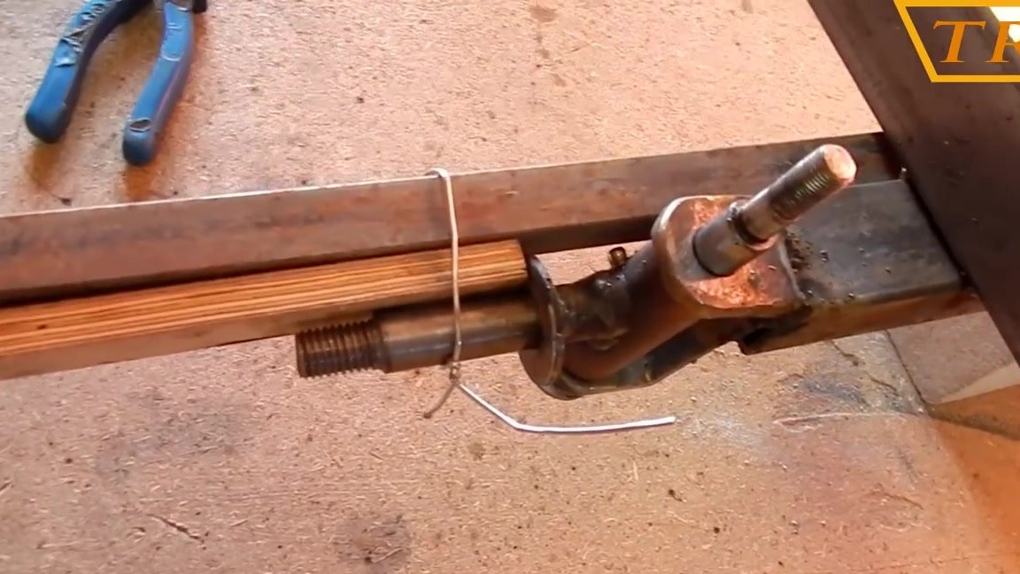
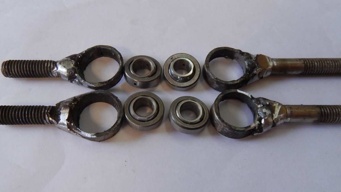
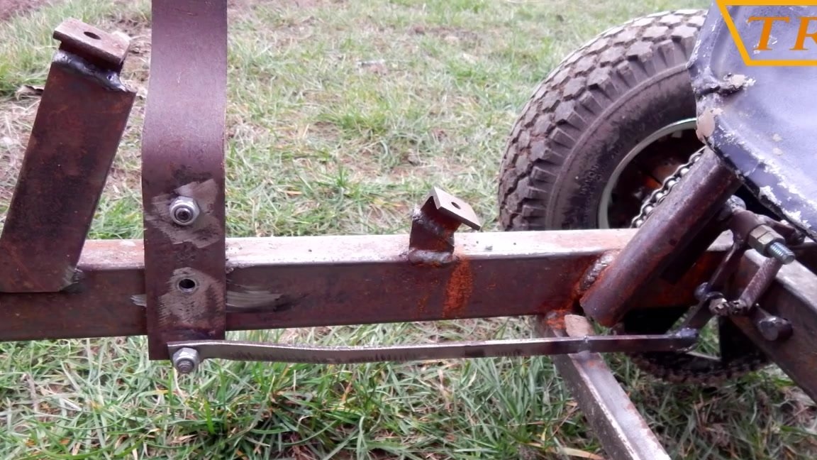
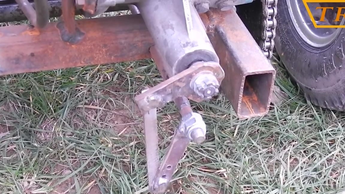
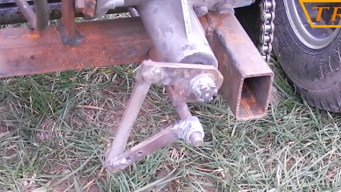
From a channel of 100 mm I make brackets to which rotary trunnions will be attached.
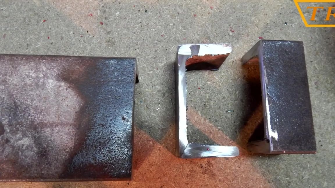
Under the internal size of the channel, bushings with holes for the connecting rod were machined.

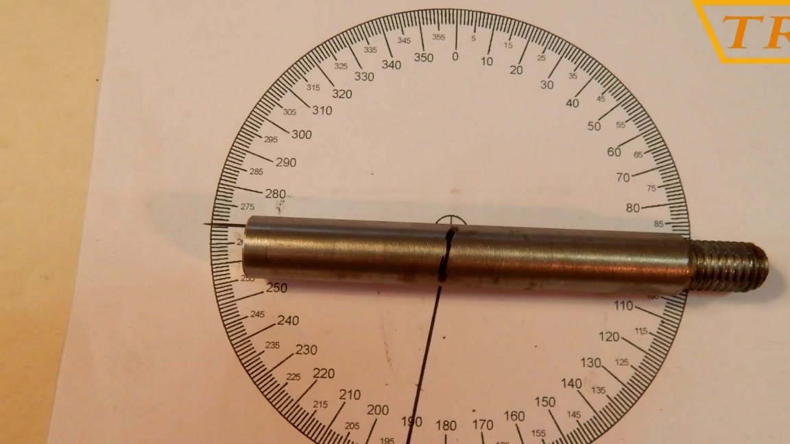
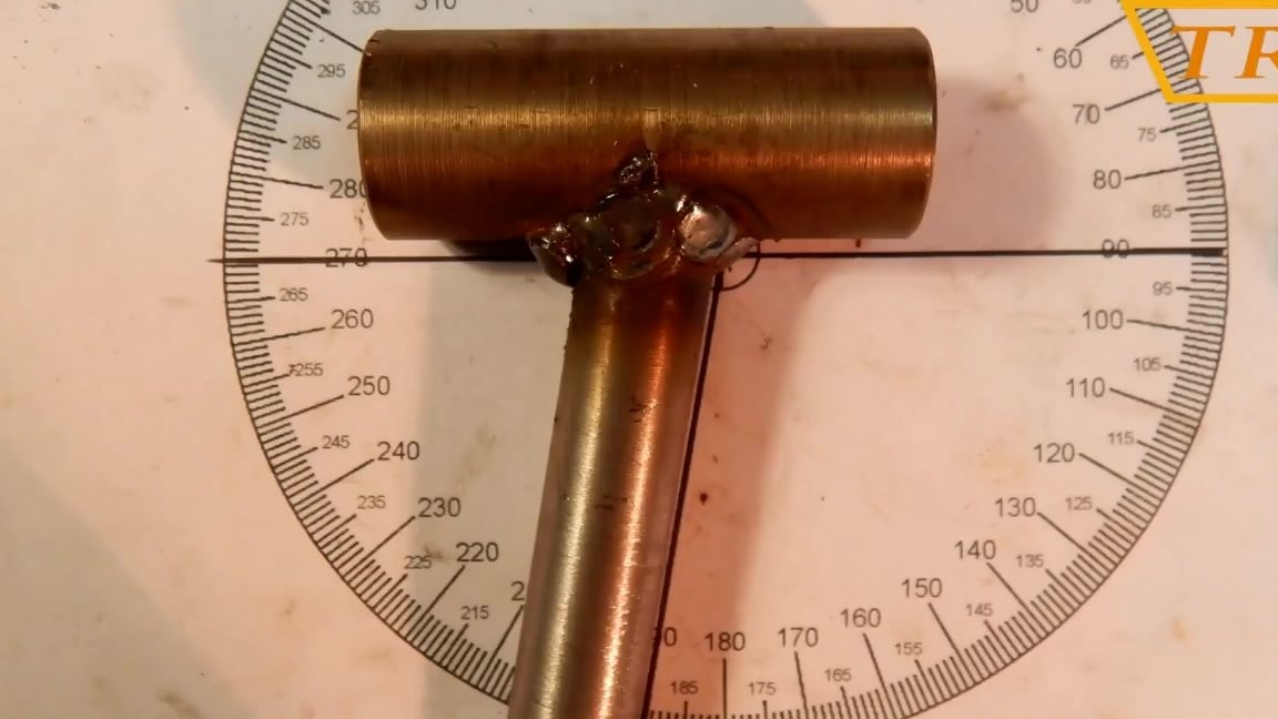
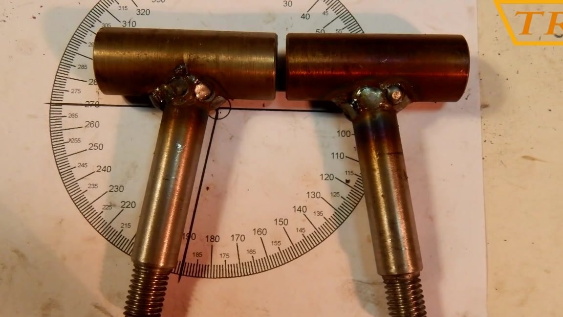
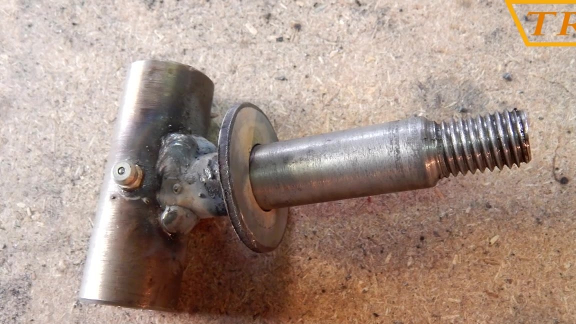
The pivot pin is welded from the shaft and axis at an angle of 10 °, for greater controllability and stability of the machine.
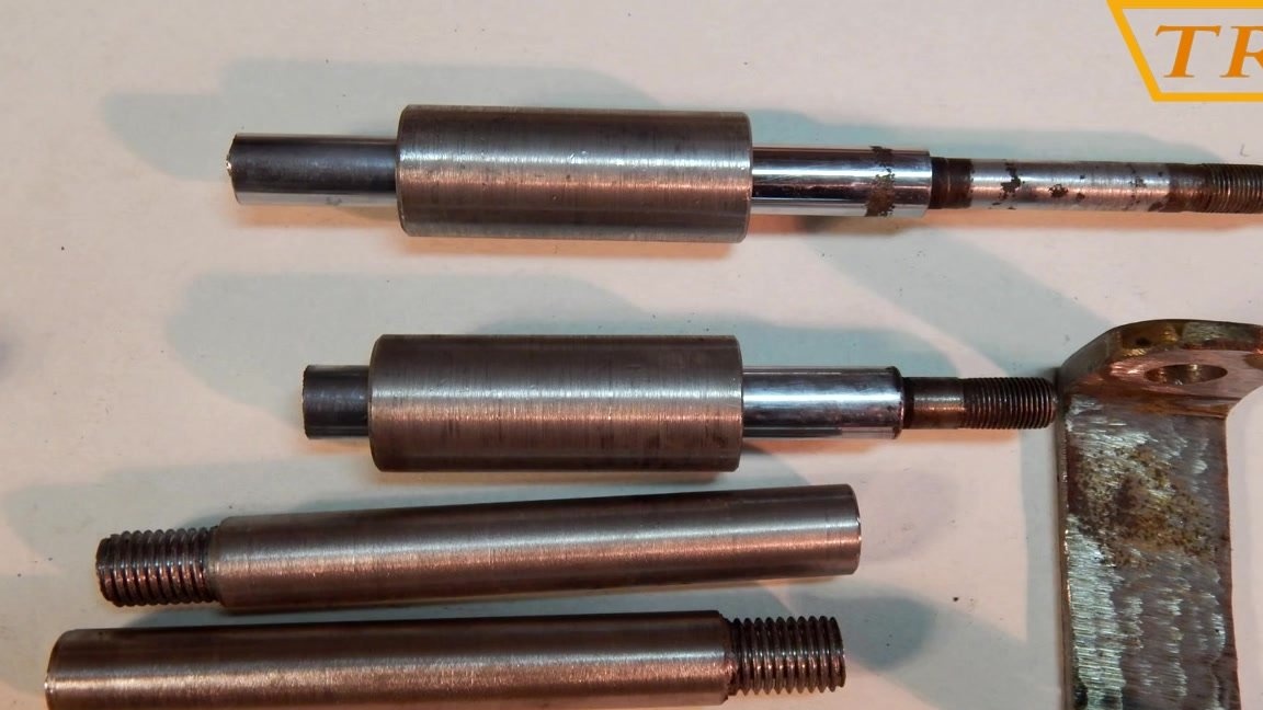
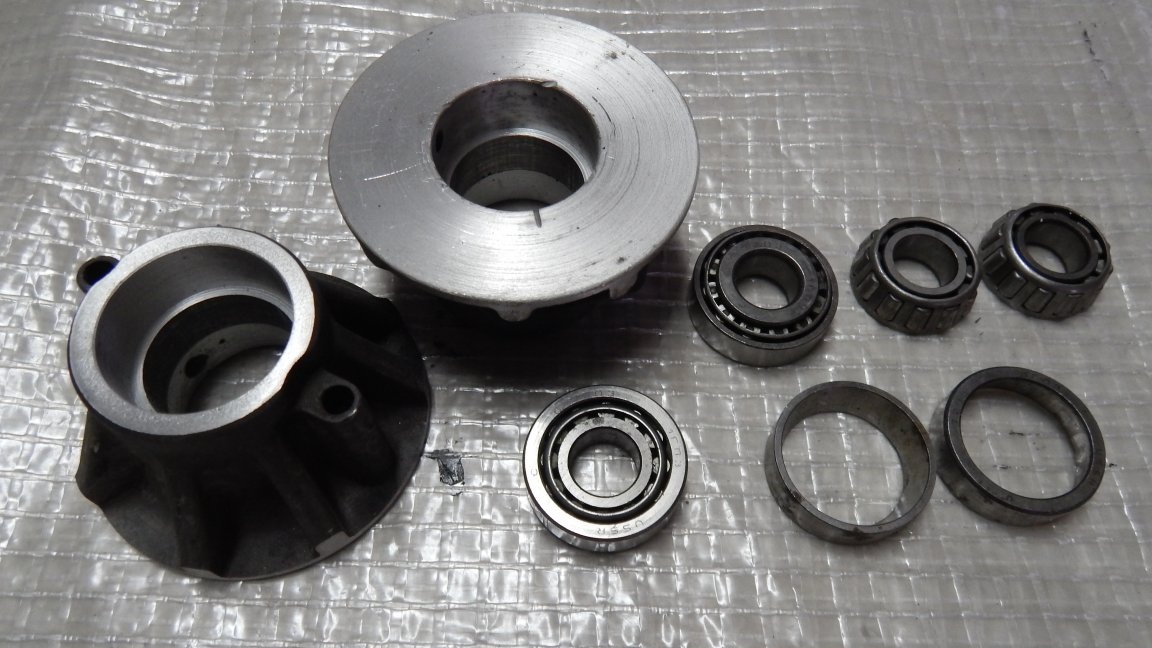
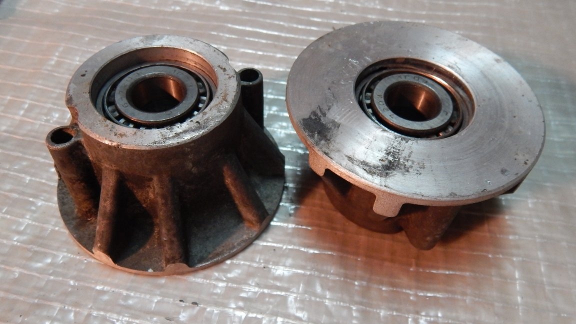
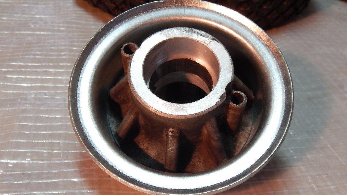
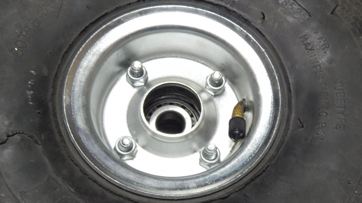
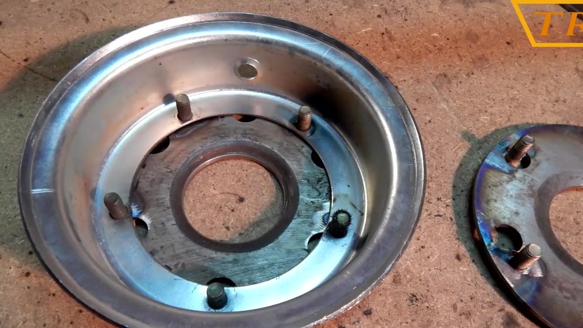
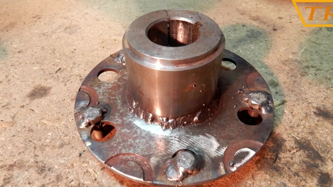
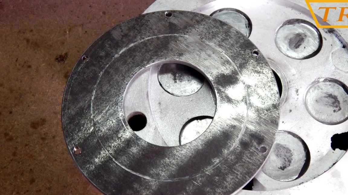
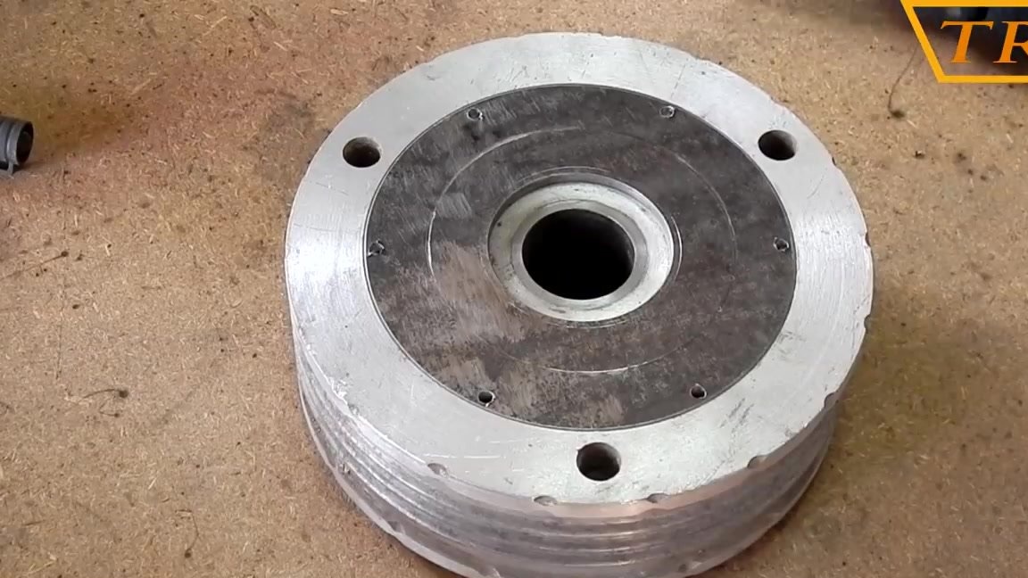
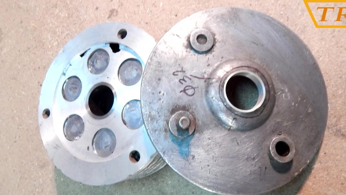
The front wheel hubs are machined from the body of the automobile pump. I can’t say for sure from which car because I found these cases for the reception of scrap metal.
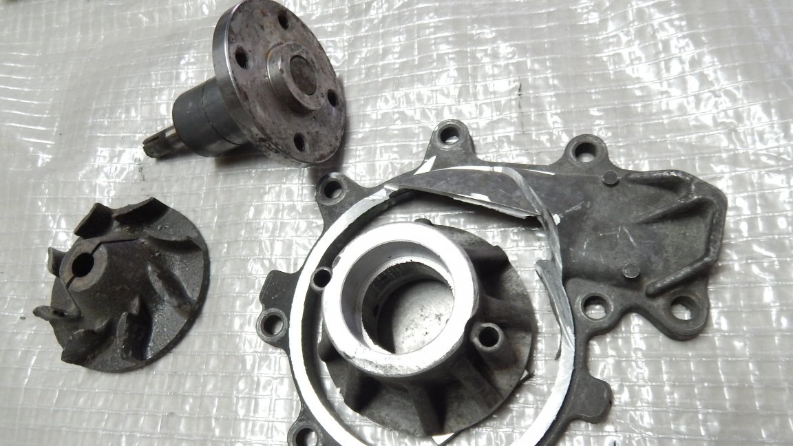
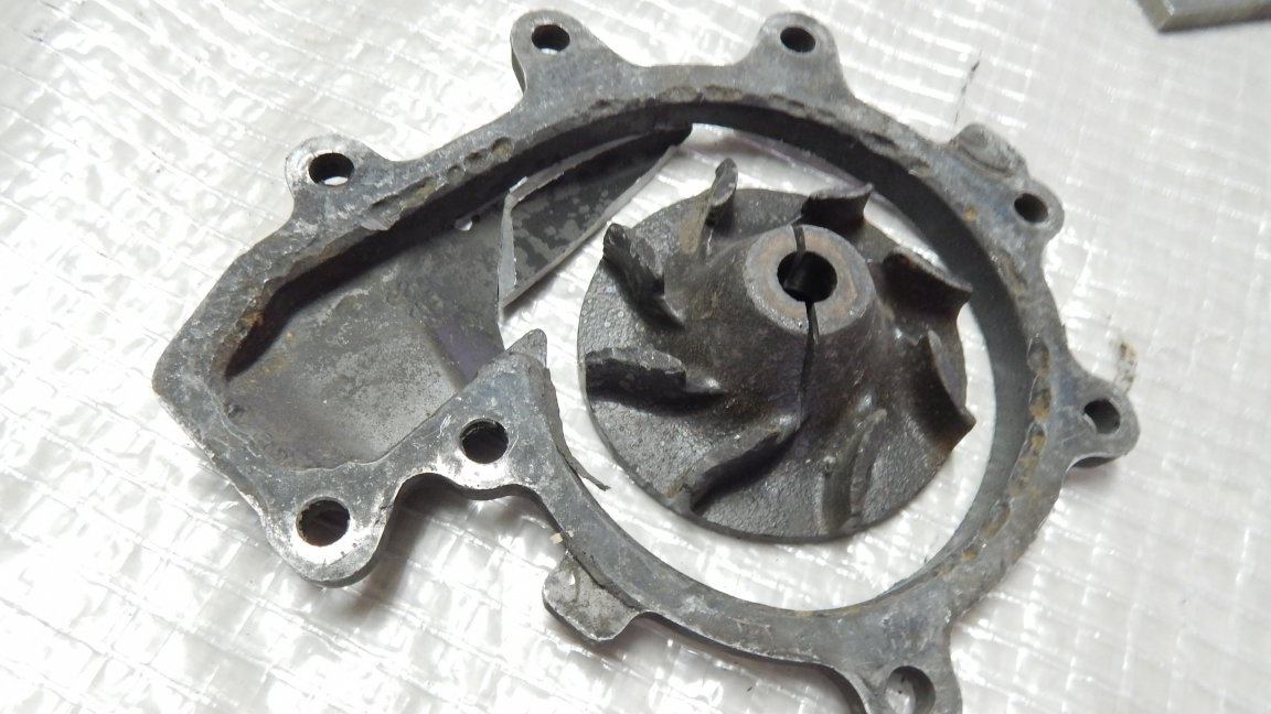
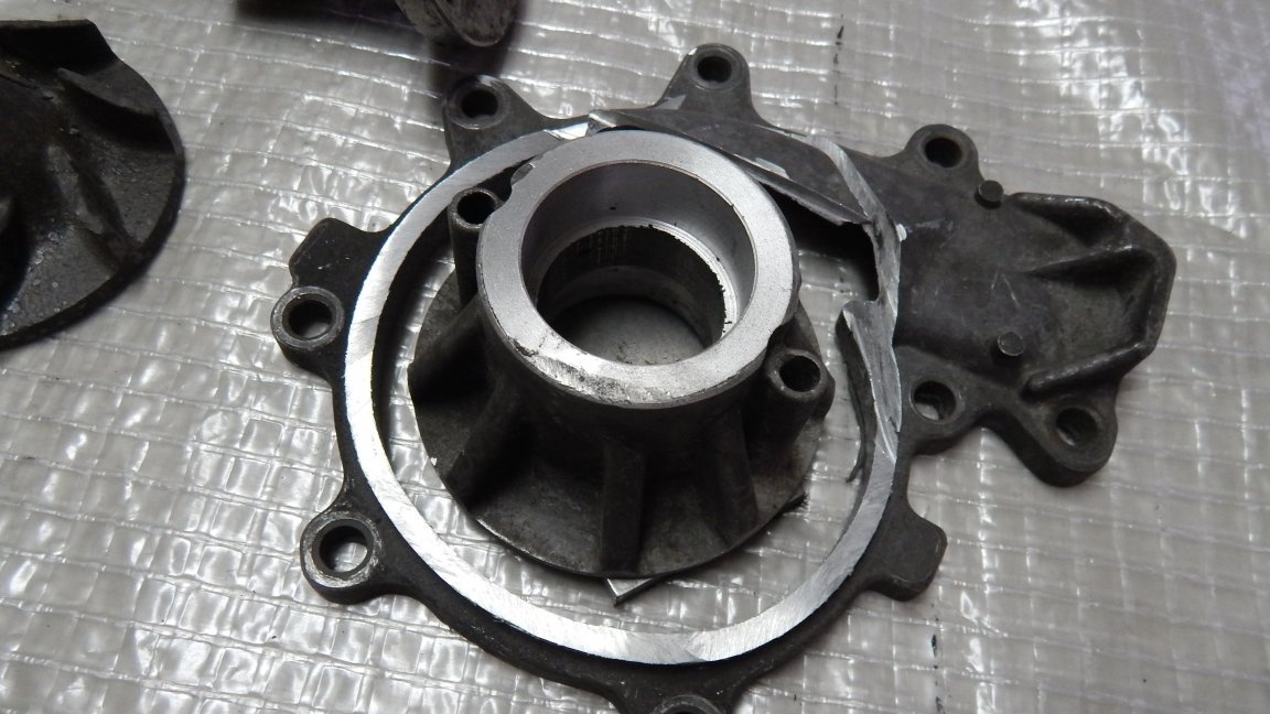
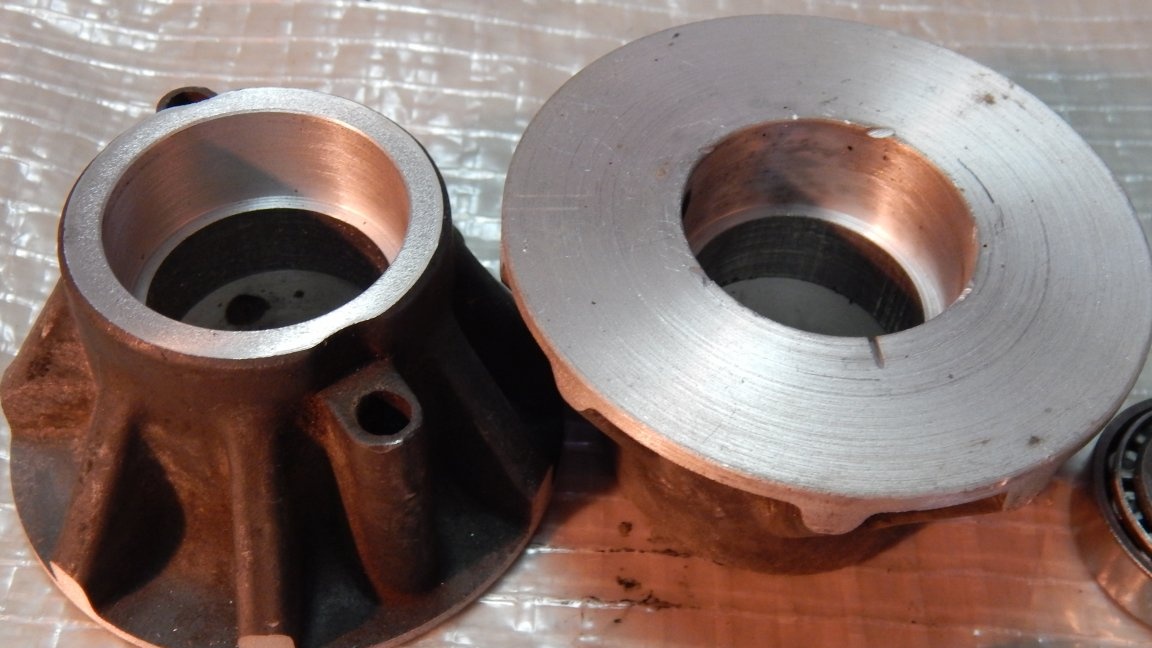
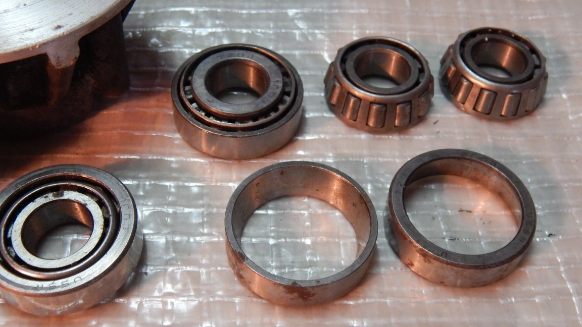
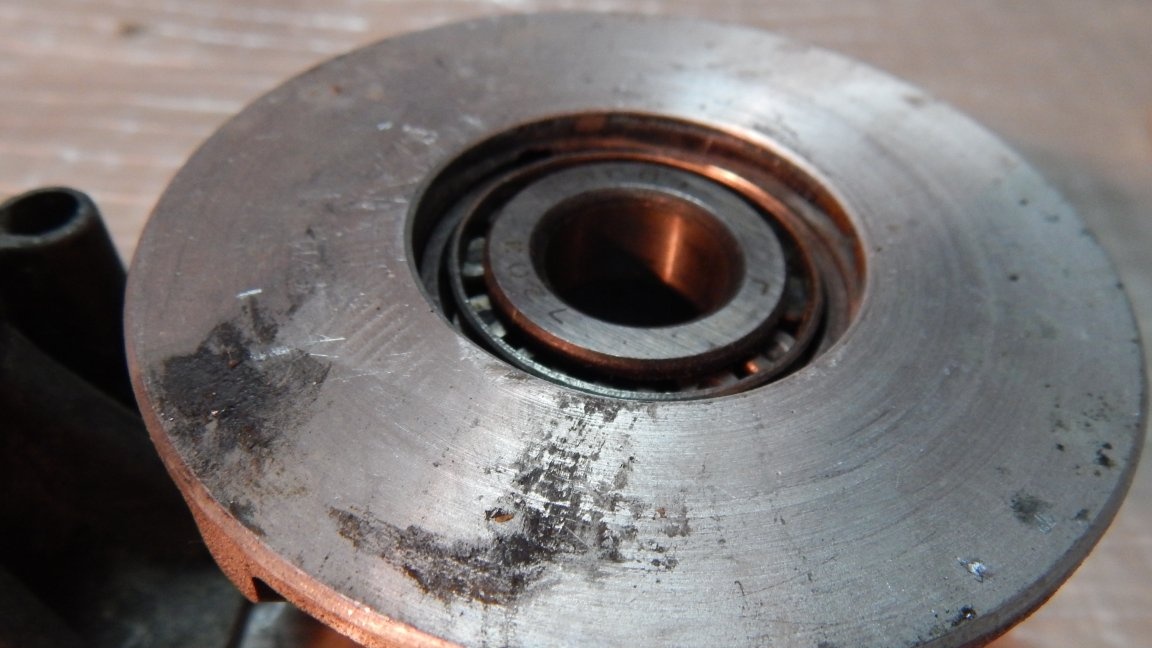
Tapered bearings are pressed into the hub.
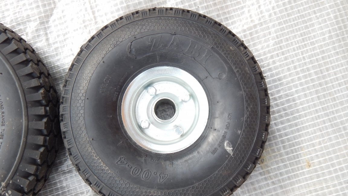
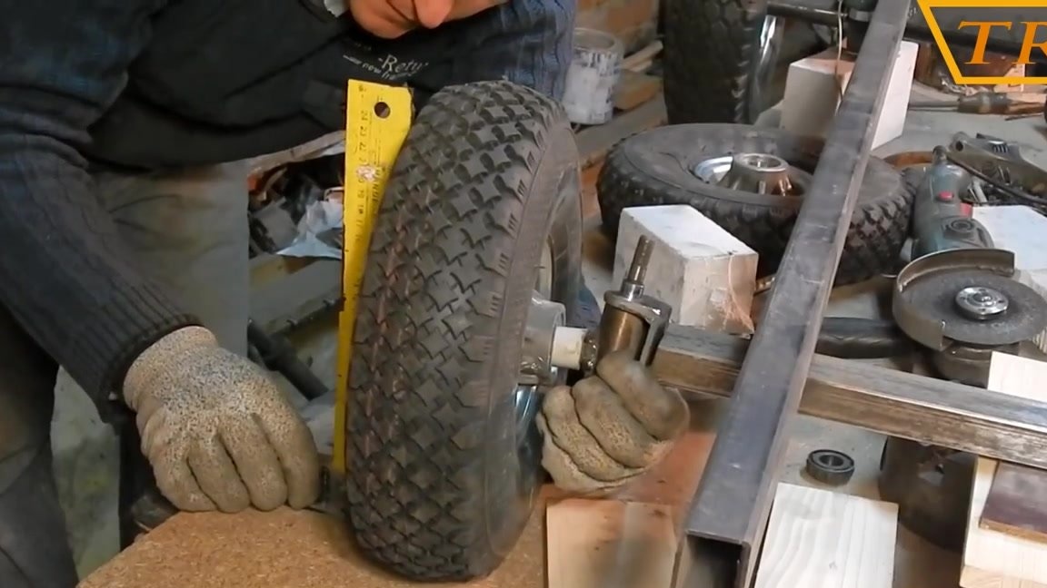
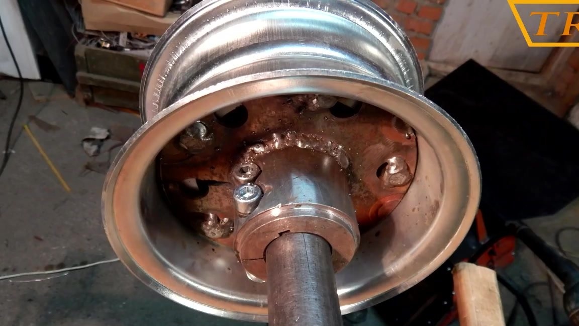
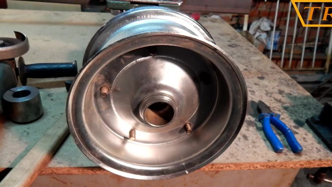
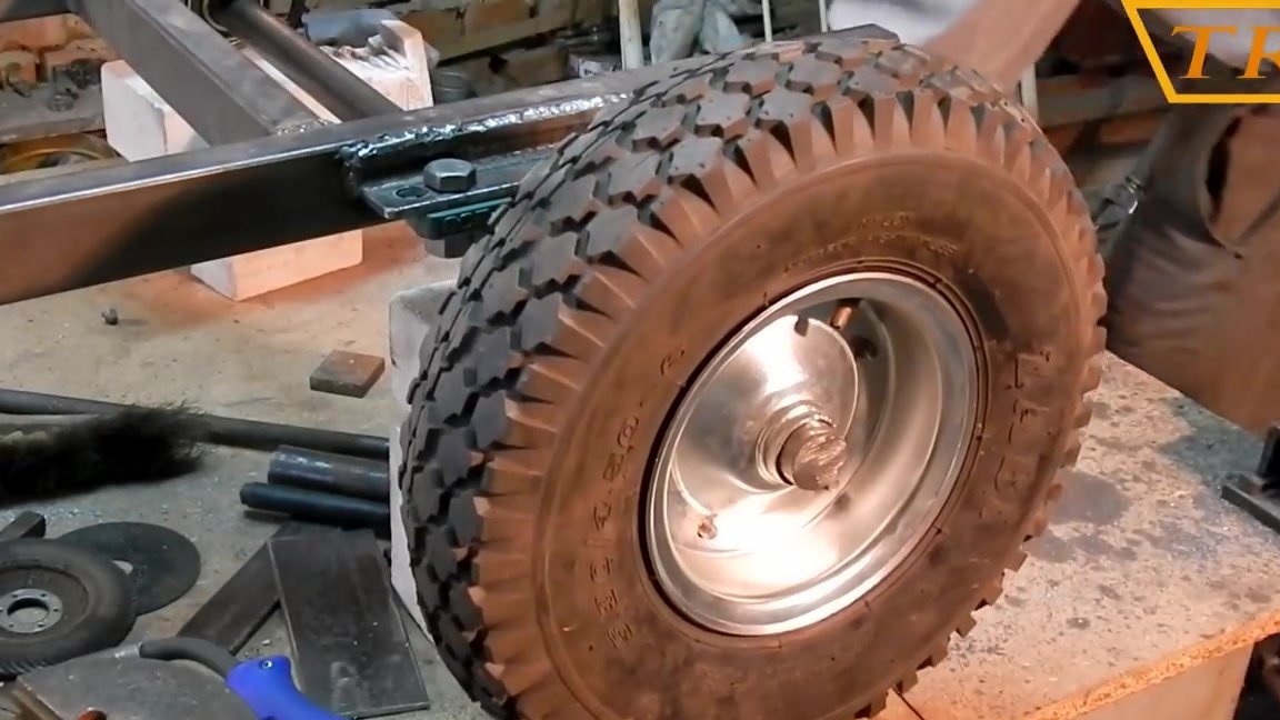
Front wheels from a garden wheelbarrow with a diameter of 300 mm.
The inside of the discs was grooved, and the excess was cut off so as not to interfere with the landing of the hubs.
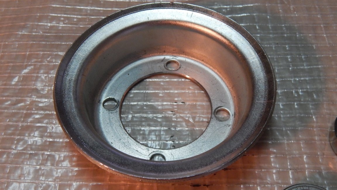
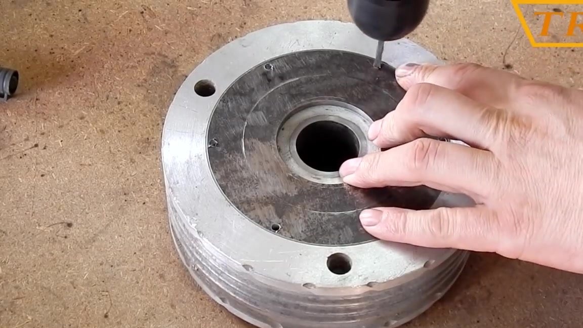
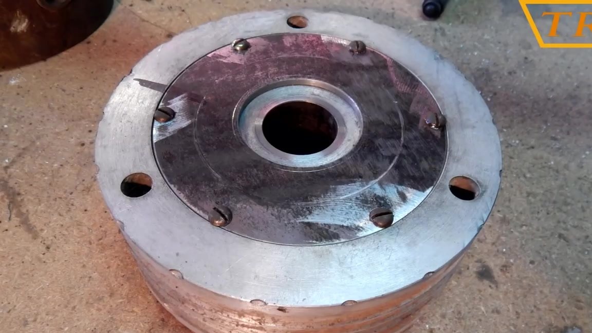
I drilled holes in the hubs for mounting discs and bolted them.
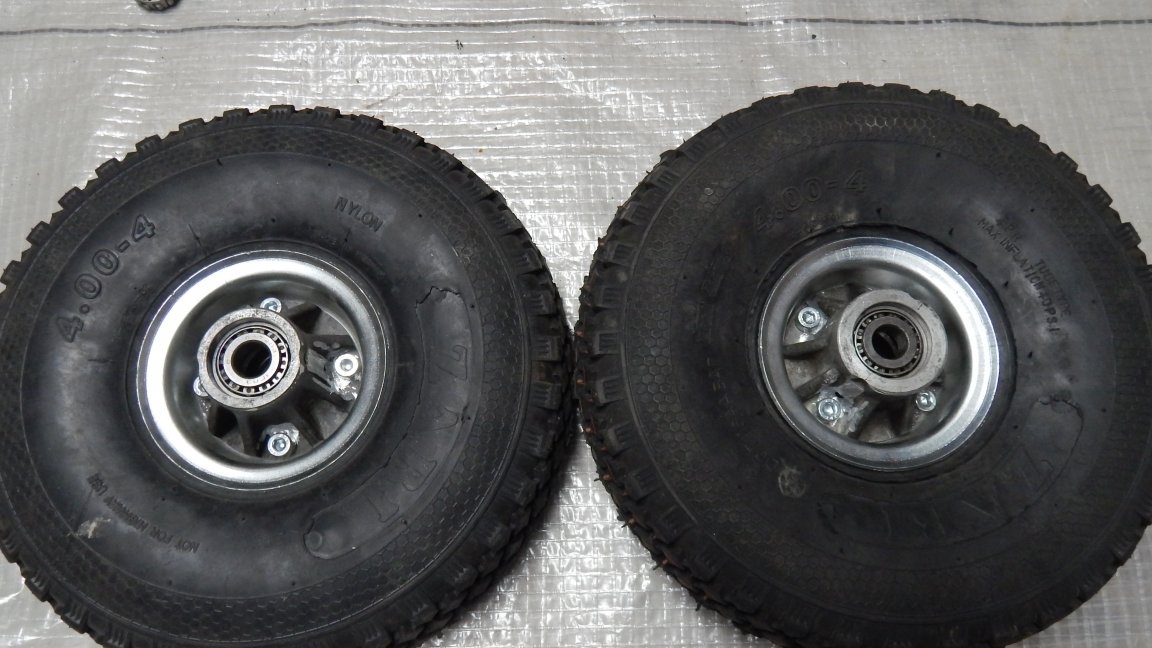
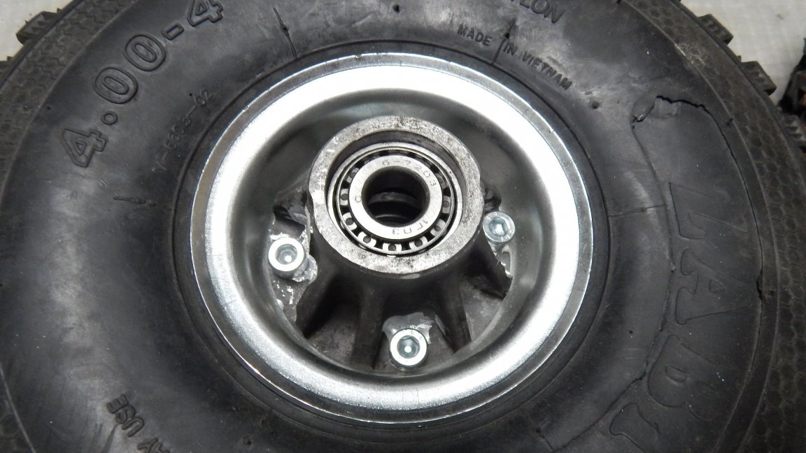
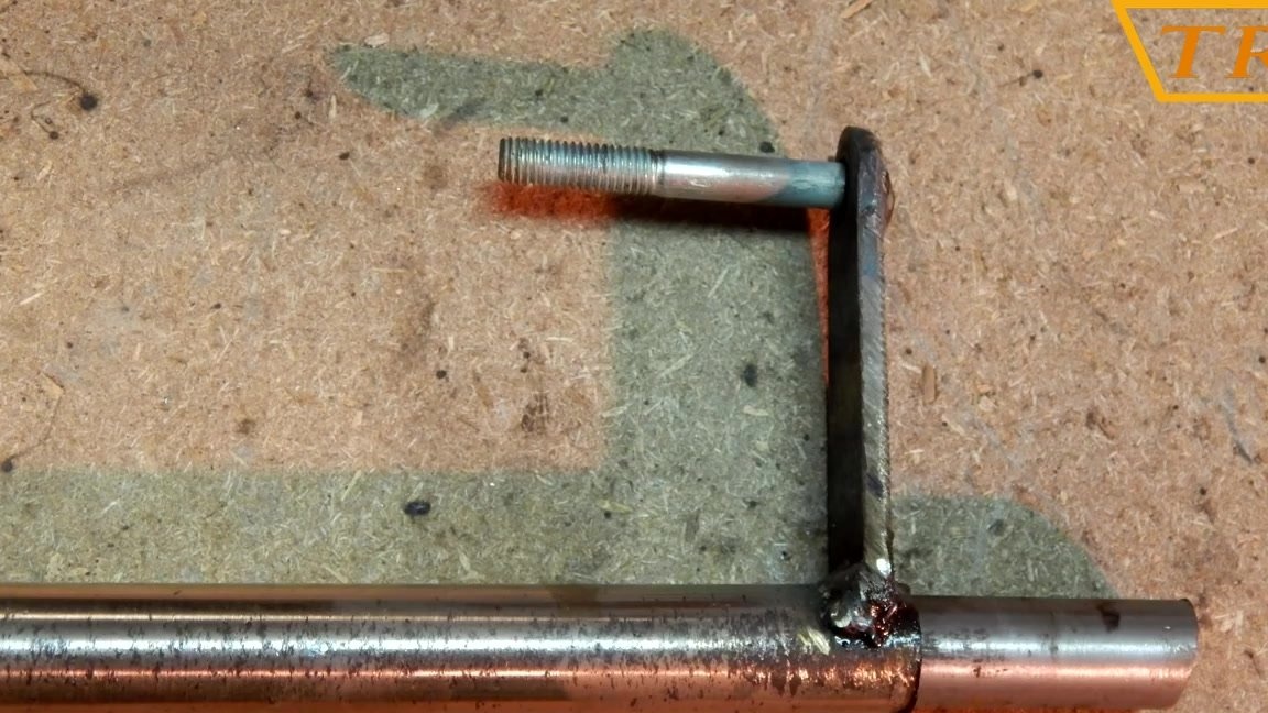
A thrust washer has been welded to the wheel axis, into which the hub bearing will abut.
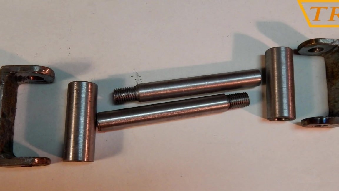
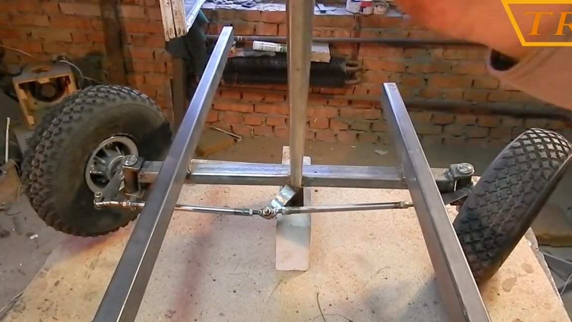
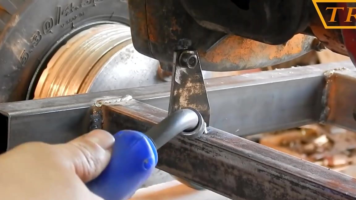
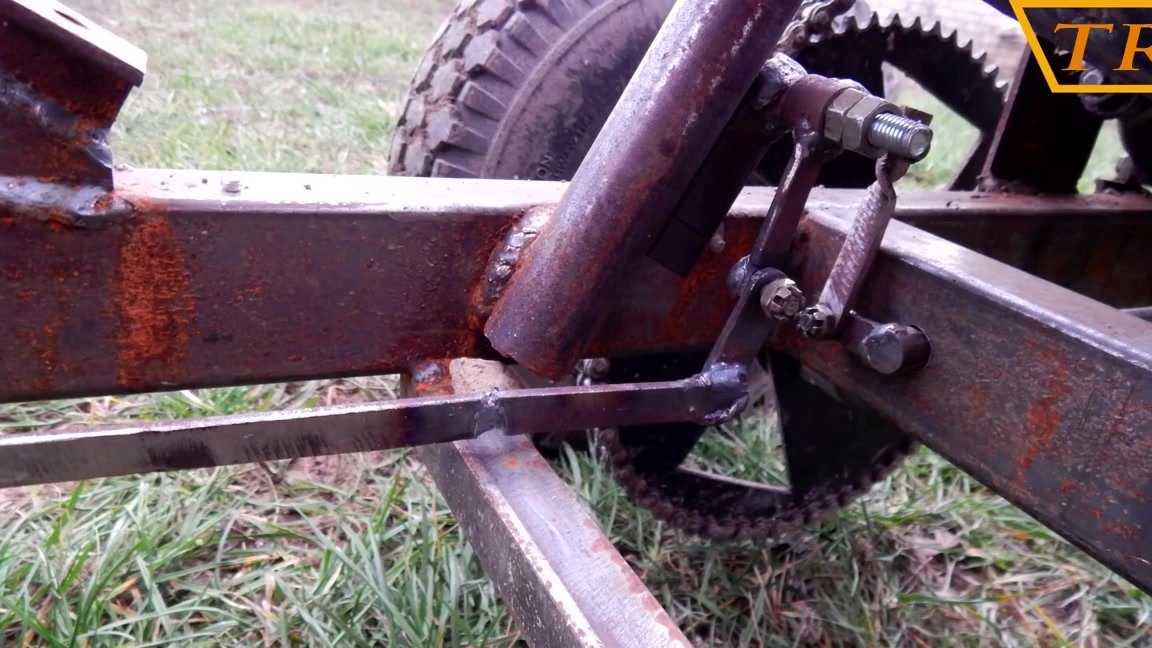
Now we connect the pivot pin to the bracket with the rod. The hub with the wheel bolted is mounted on the axle and fixed with nuts. Now cut the front beam at an angle of 10 °, and weld to it a bracket with a pin and a wheel.
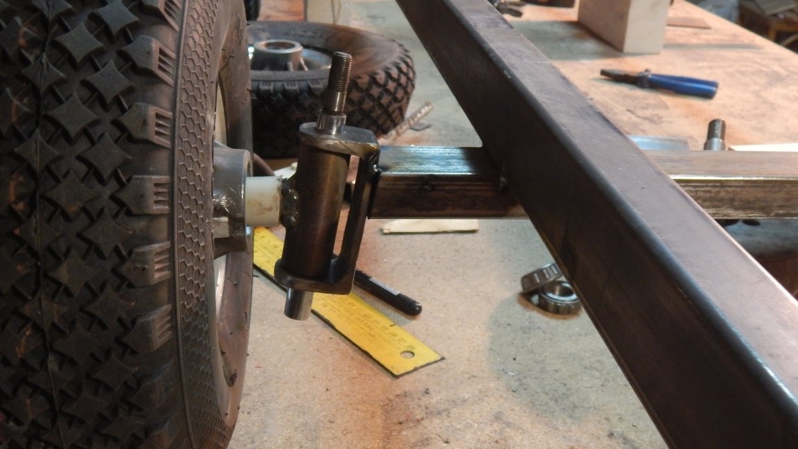
The bracket is tilted forward by 10 °.
Video instruction!
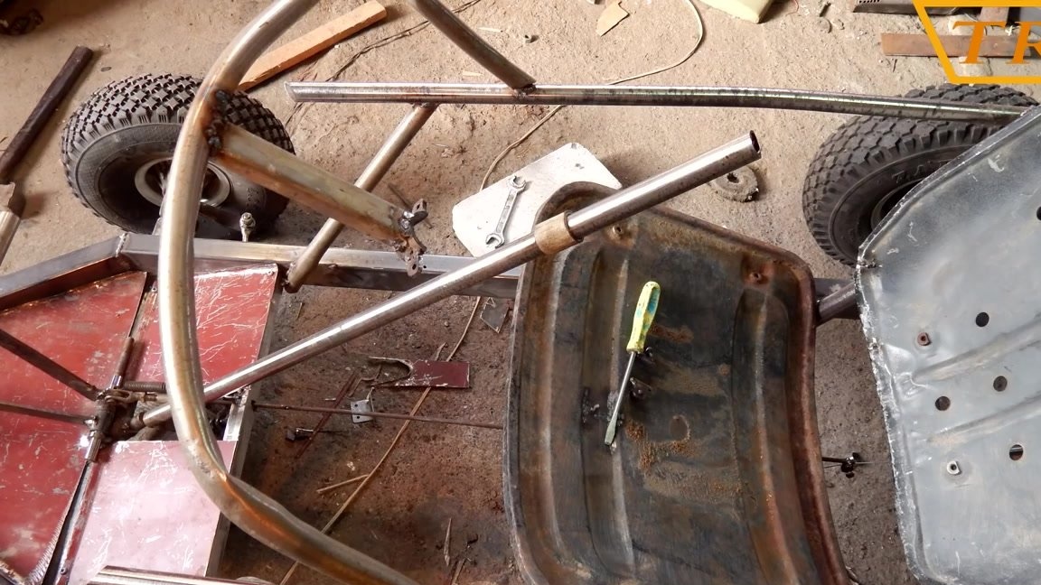
Step Three: Steering Calculation
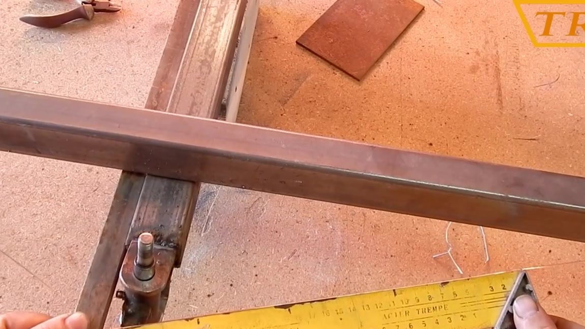
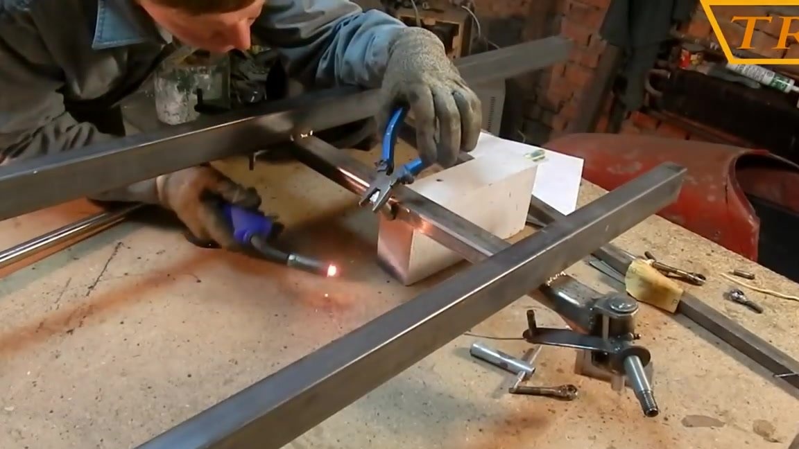
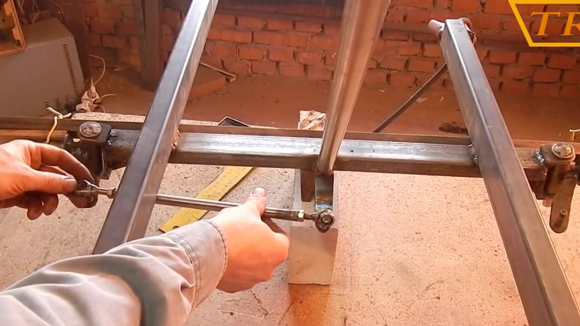
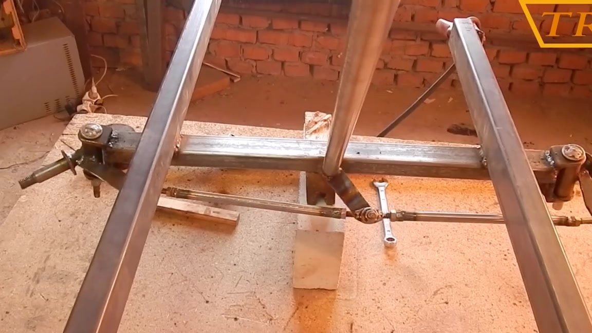
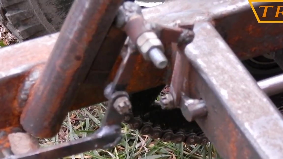
Now proceed to the calculation of the steering. To do everything right, we use the Akkerman formula. To begin with, I fix the pivot pins at the same level, and the axes should be parallel to the beam.
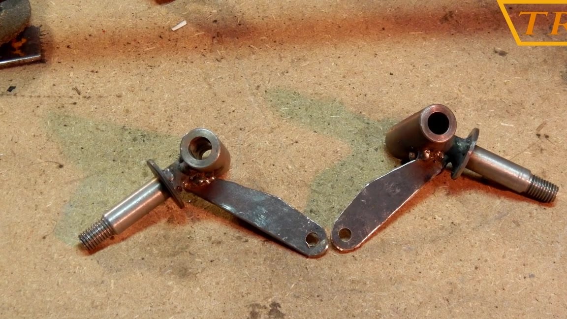
Now I make two rotary bipods from the plate.
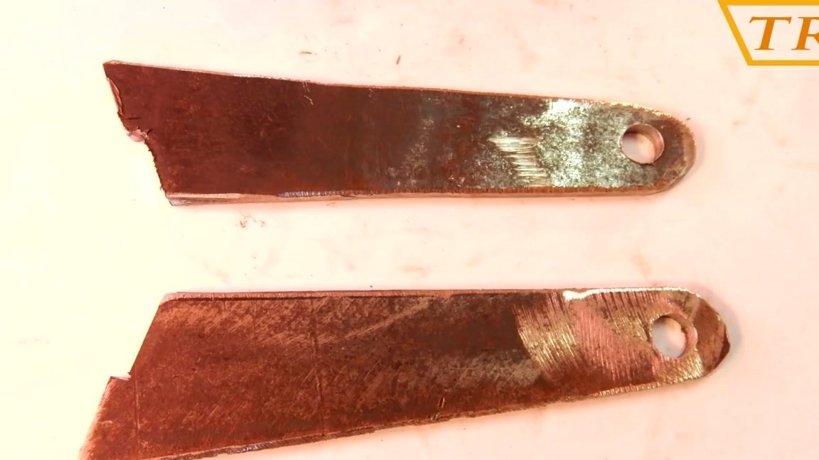
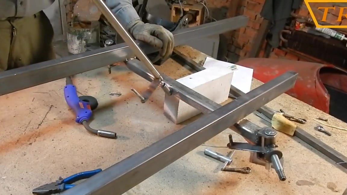
In order for the wheels at the turns to describe the correct radius, you need to weld the bipods to the pins at the right angle. To do this, I tied the wire to the center of the rear axle, and pulled it to the pivot pin; now you can see at what angle the bipod needs to be welded.
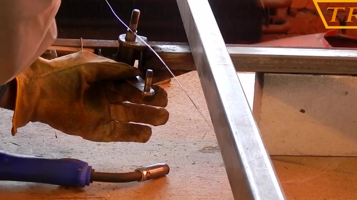
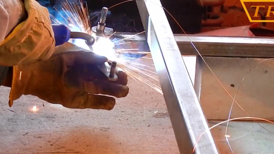
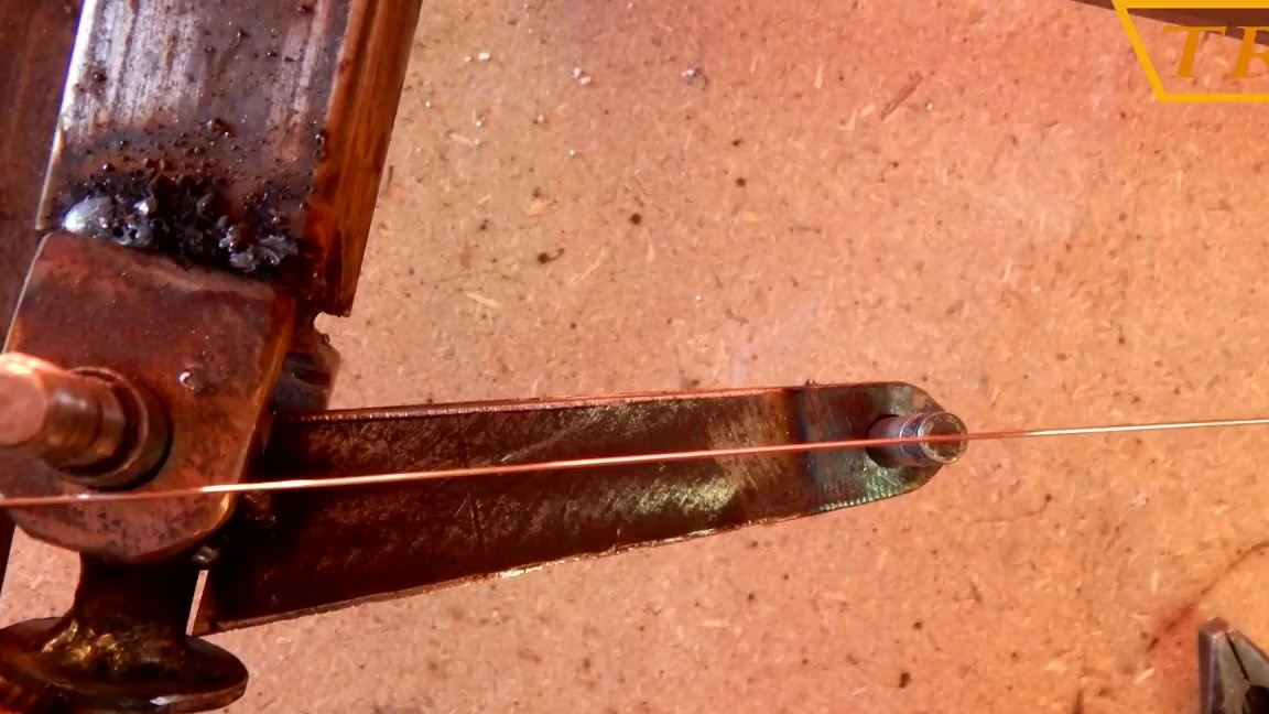
We repeat the exact same procedure on the other hand and weld the butt joints.
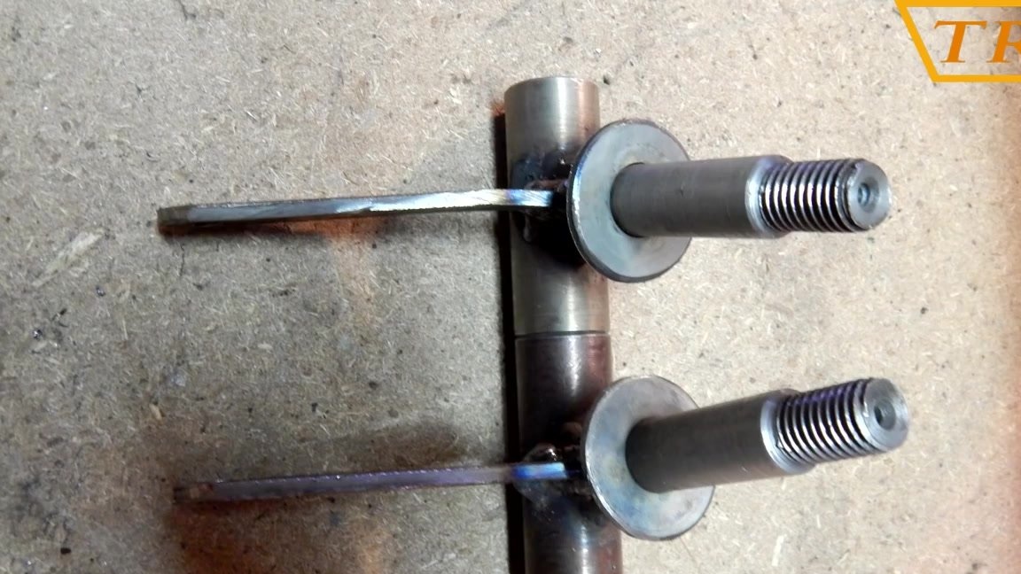
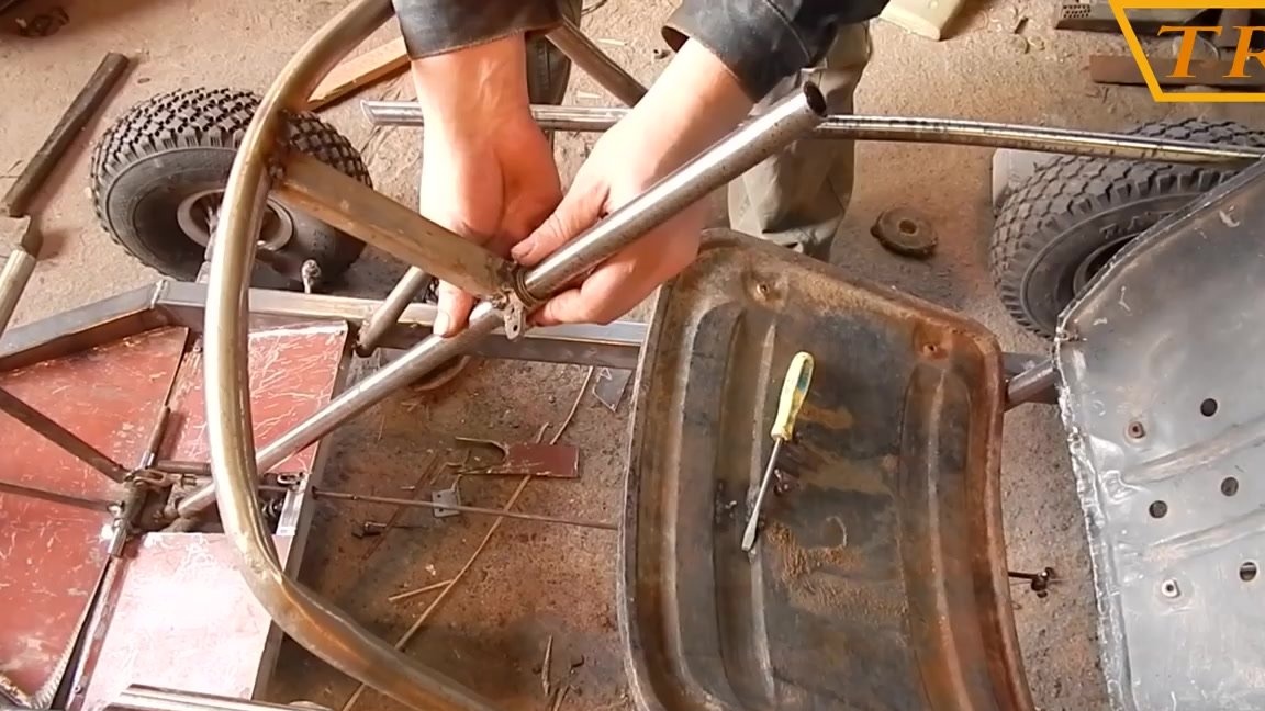
I weld a bipod to the steering shaft made of a tube.
I weld a piece of the shaft that enters the tube of the steering shaft to the frame.
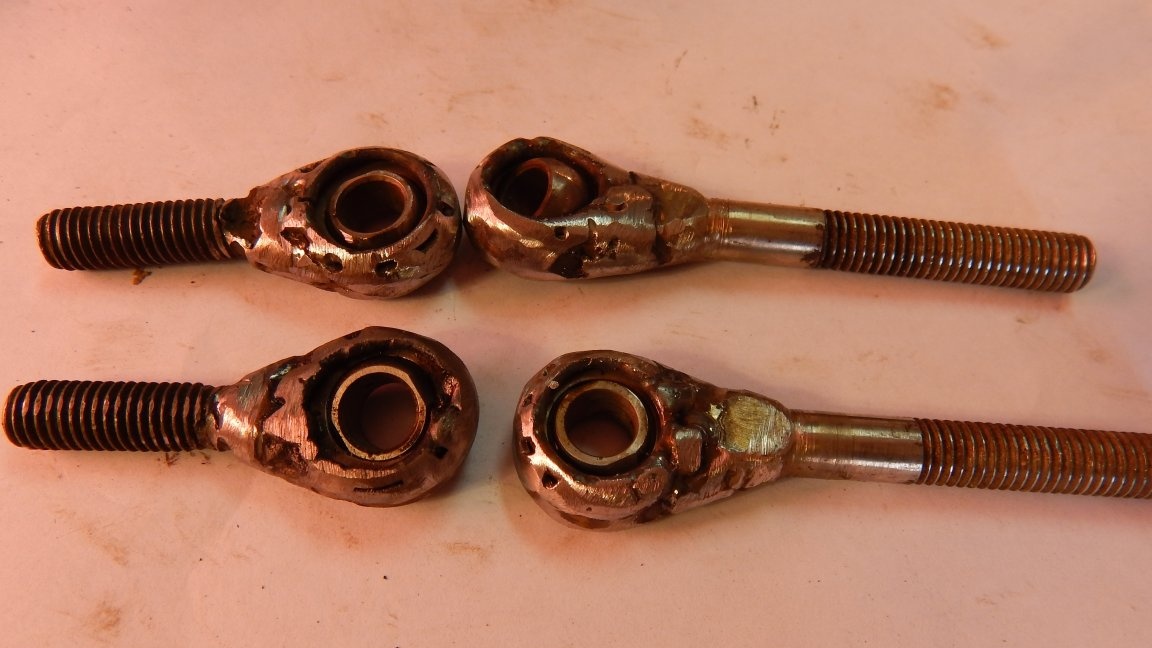
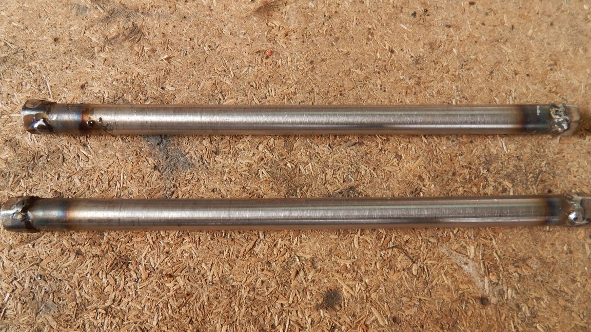
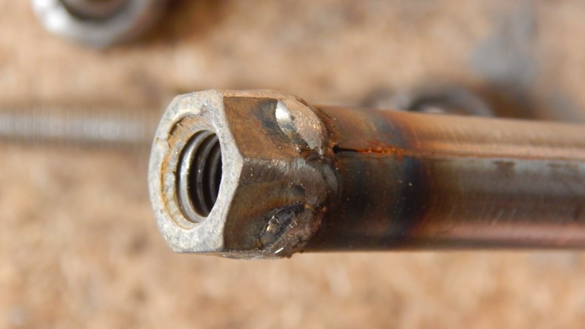
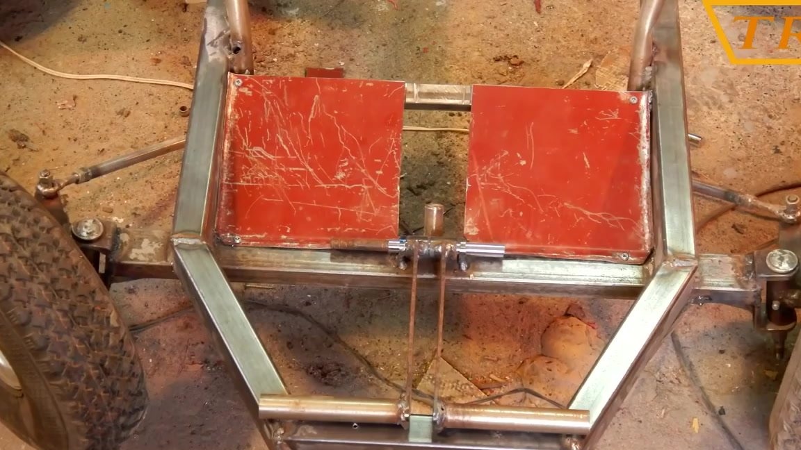
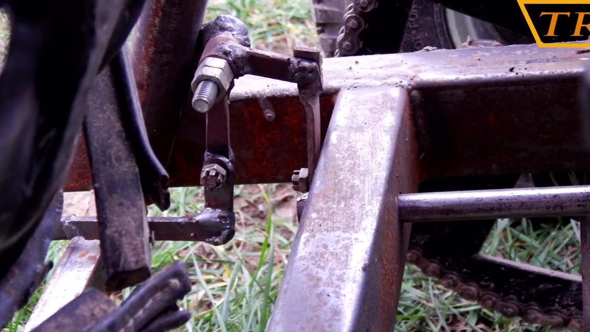
I made steering rods from tubes at the ends of which I welded nuts to adjust the length of rods.
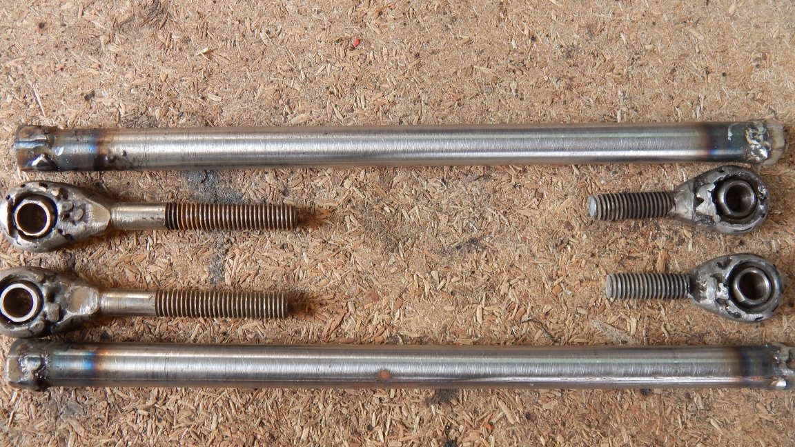
I put the rods in place and fix them with nuts.
Video instruction!
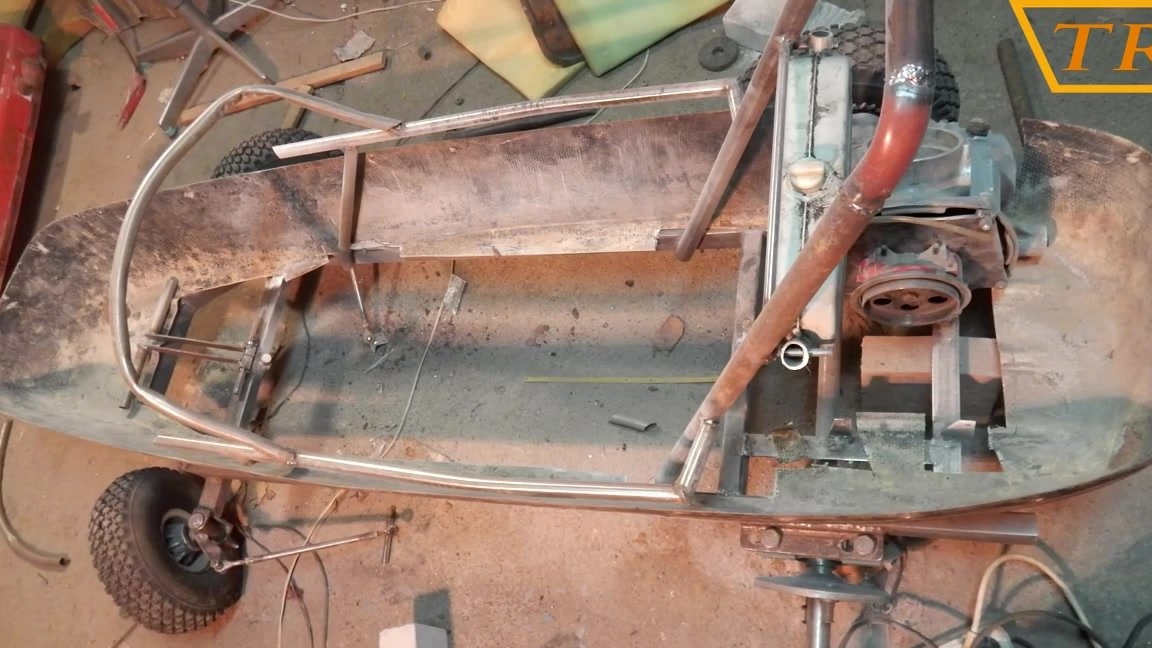
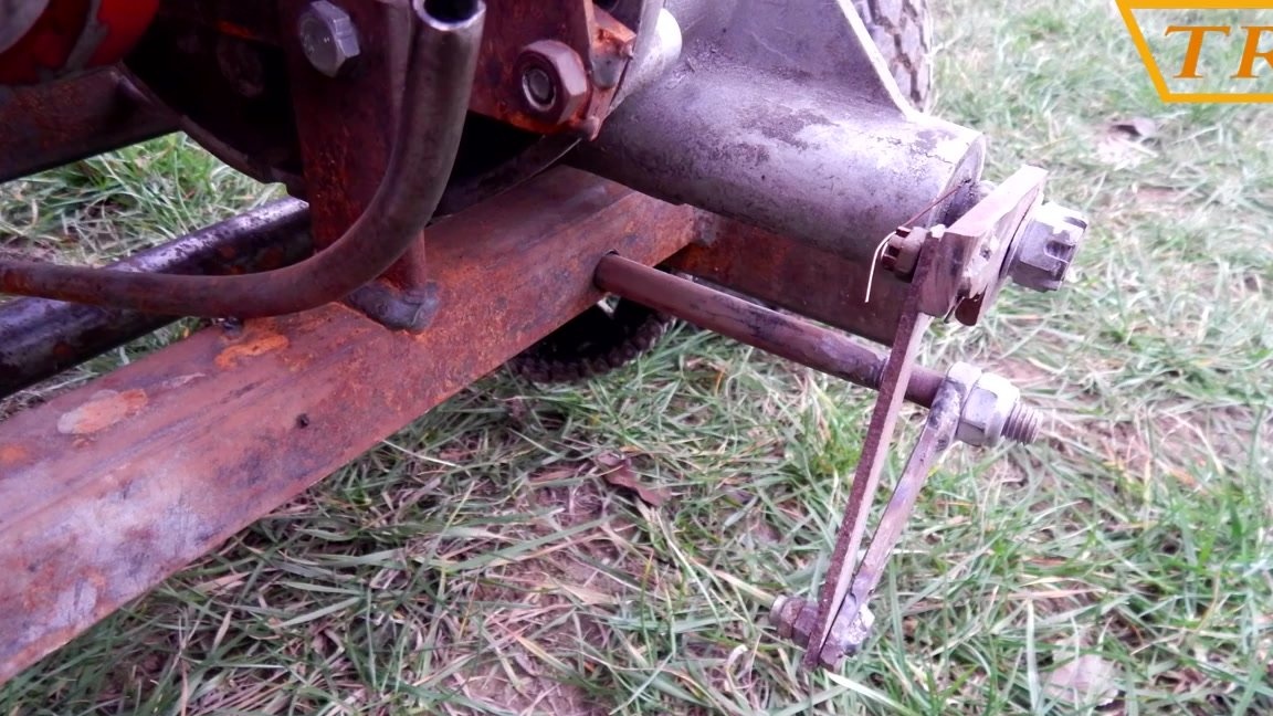
Fourth step: installing the engine and rear axle
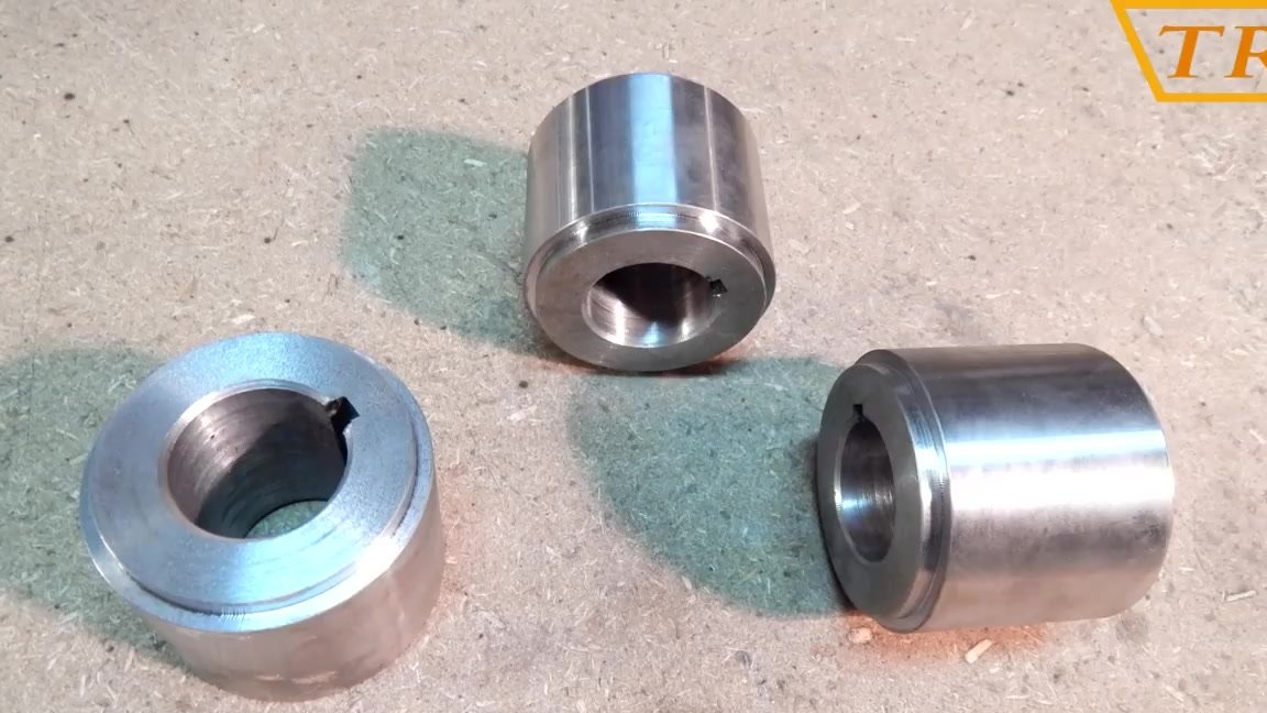
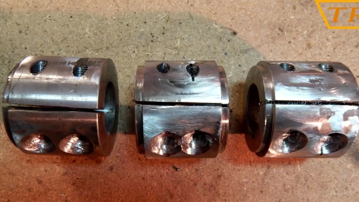
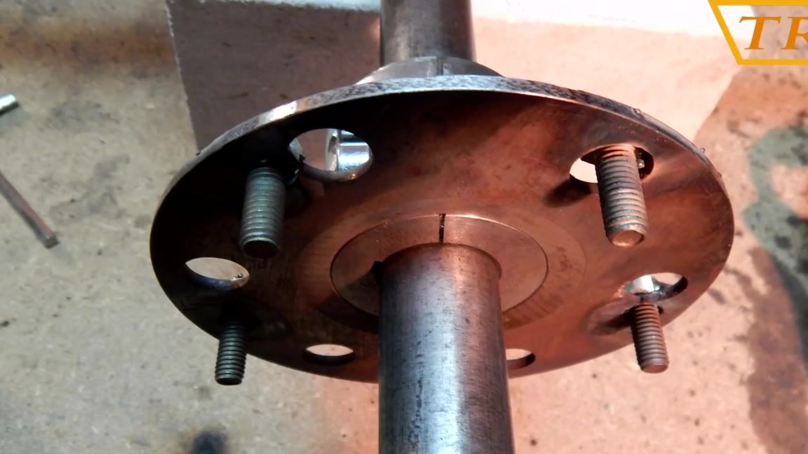
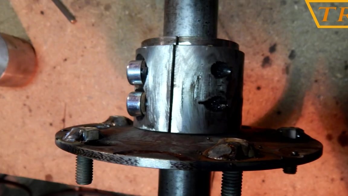
I cut the bushings ordered earlier from the turner in one place in order to easily put them on the axle, and for fixing, drill holes in the bushings and cut the M8 thread for the bolts.
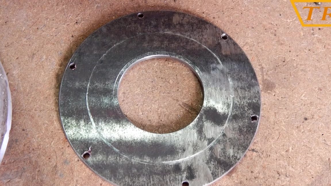
Washers were machined from 4 mm sheet metal to which the wheels would be screwed. The inside of the washer is the same size as the sleeve and fits freely on it.
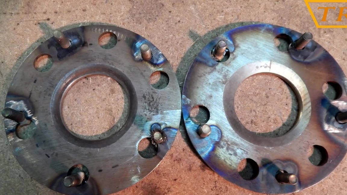
I weld the washer to the sleeve.
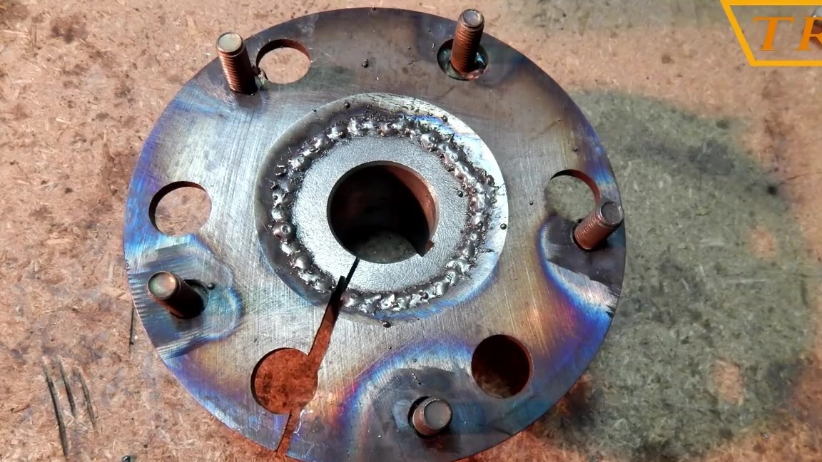
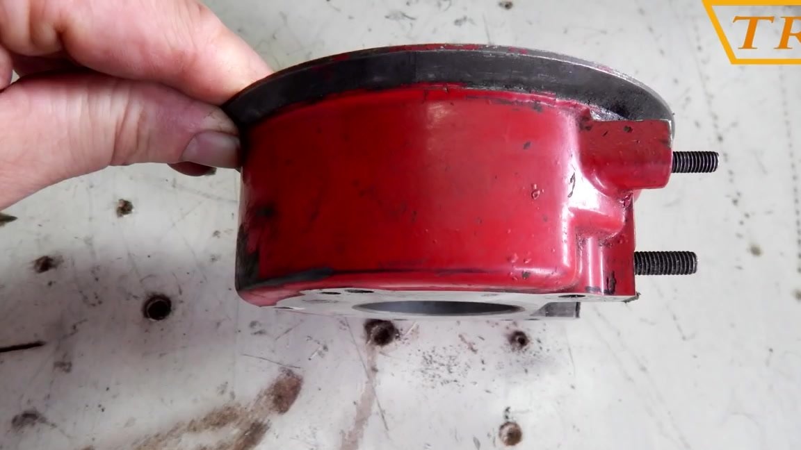
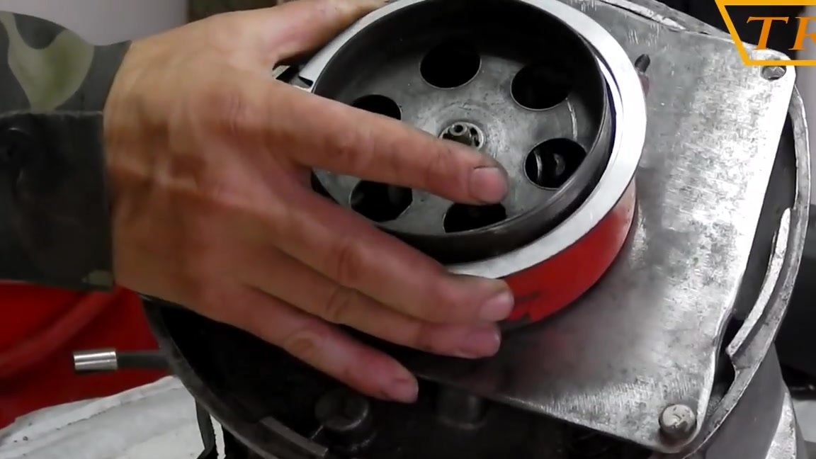
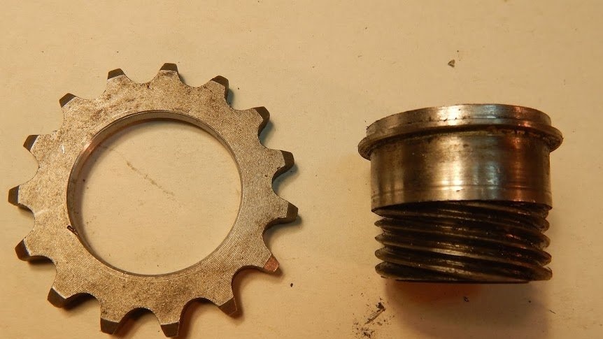
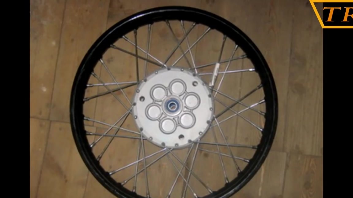
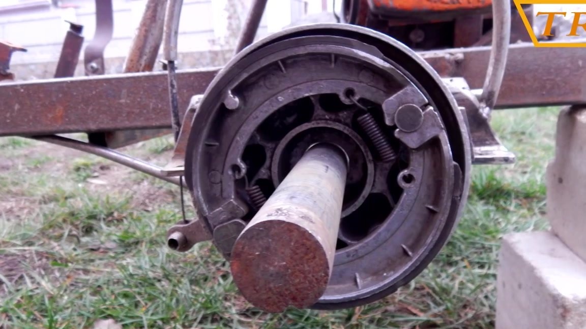
Minsk took the brake drum from the front wheel of the motorcycle. It was stitched on the outside and a groove was made under the washer.
We put the washer in place in the drum and drill holes for the bolts. We cut the M5 thread and tighten the bolts, fixing the washer in its place.
We weld the bushing to the brake drum washer.
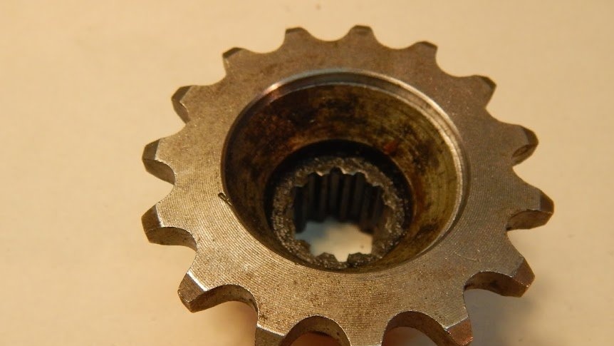
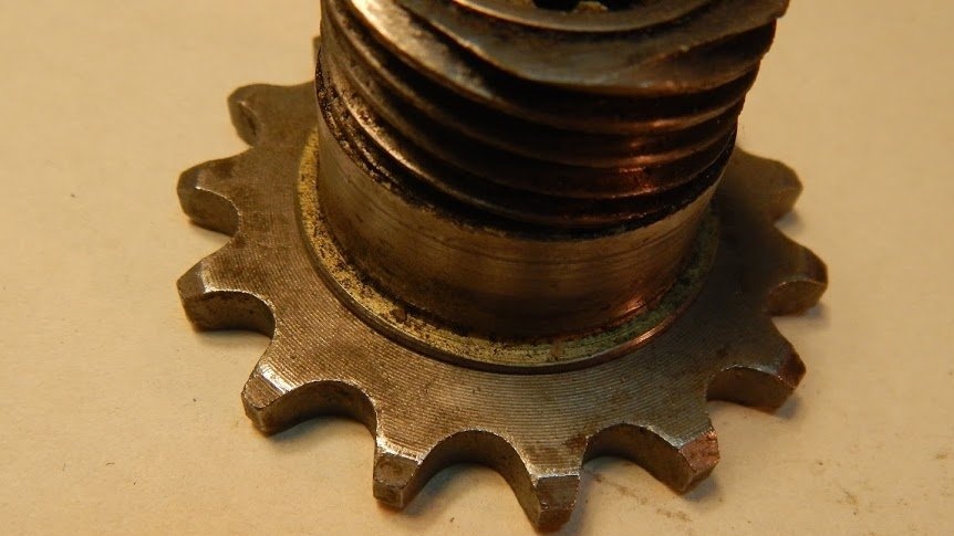
I weld a washer with bolts to the third sleeve to which the sprocket will be screwed.
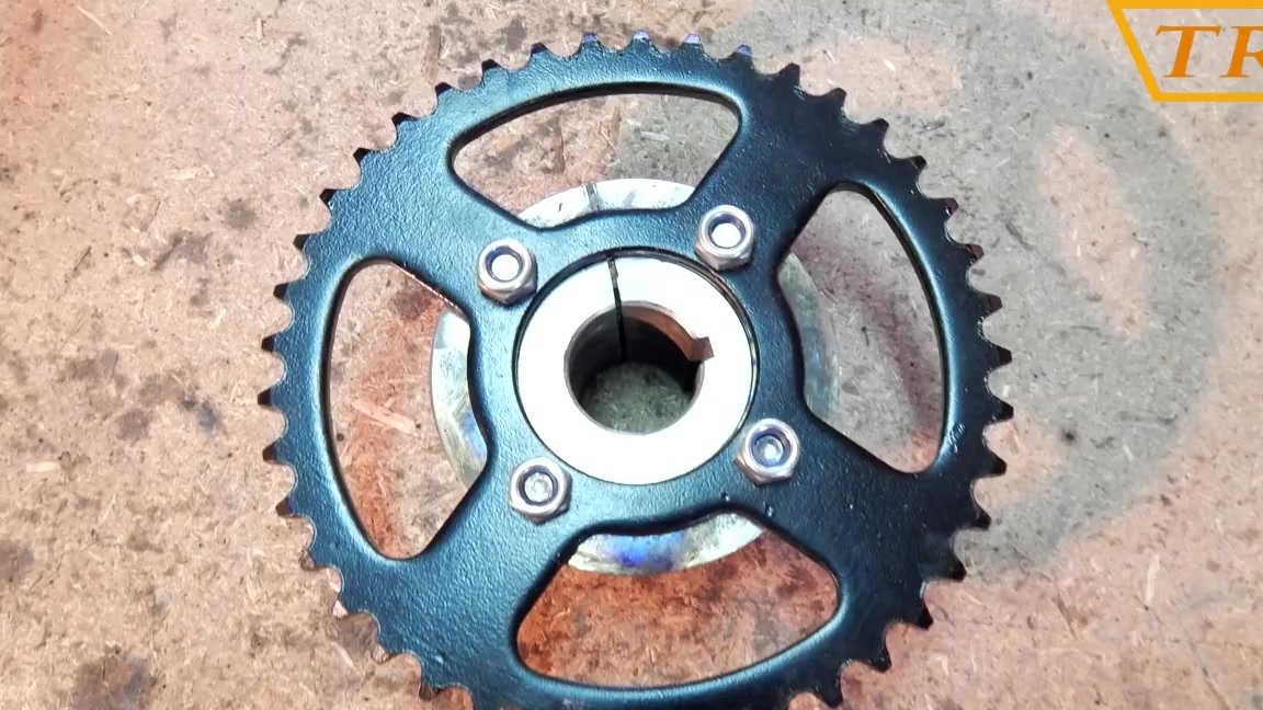
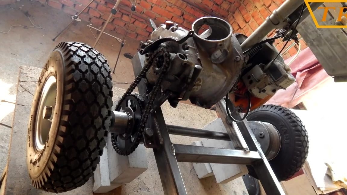
First I put a star from a Chinese moped with 428 steps for 41 teeth, but then I changed it to a makeshift because there was not enough traction.
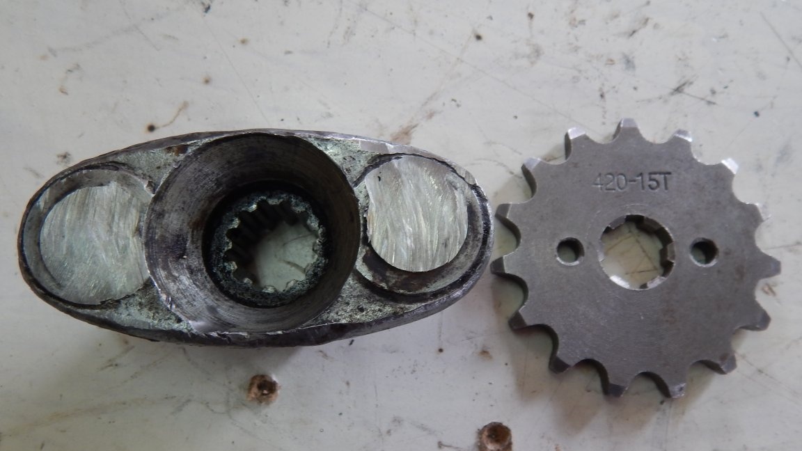
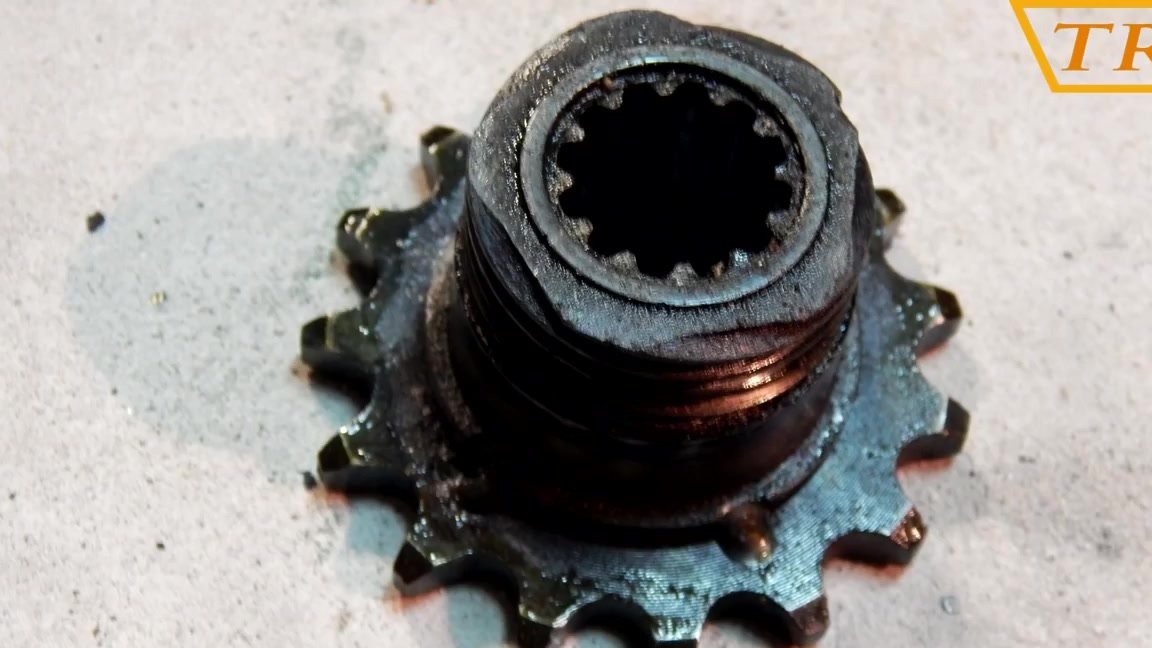
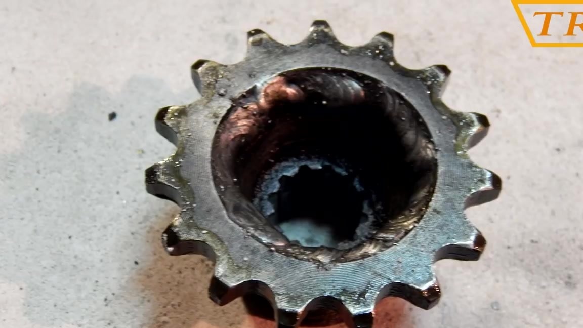
The leading star from the same moped with a pitch of 428 by 15 teeth is machined and welded to the gearbox fork.
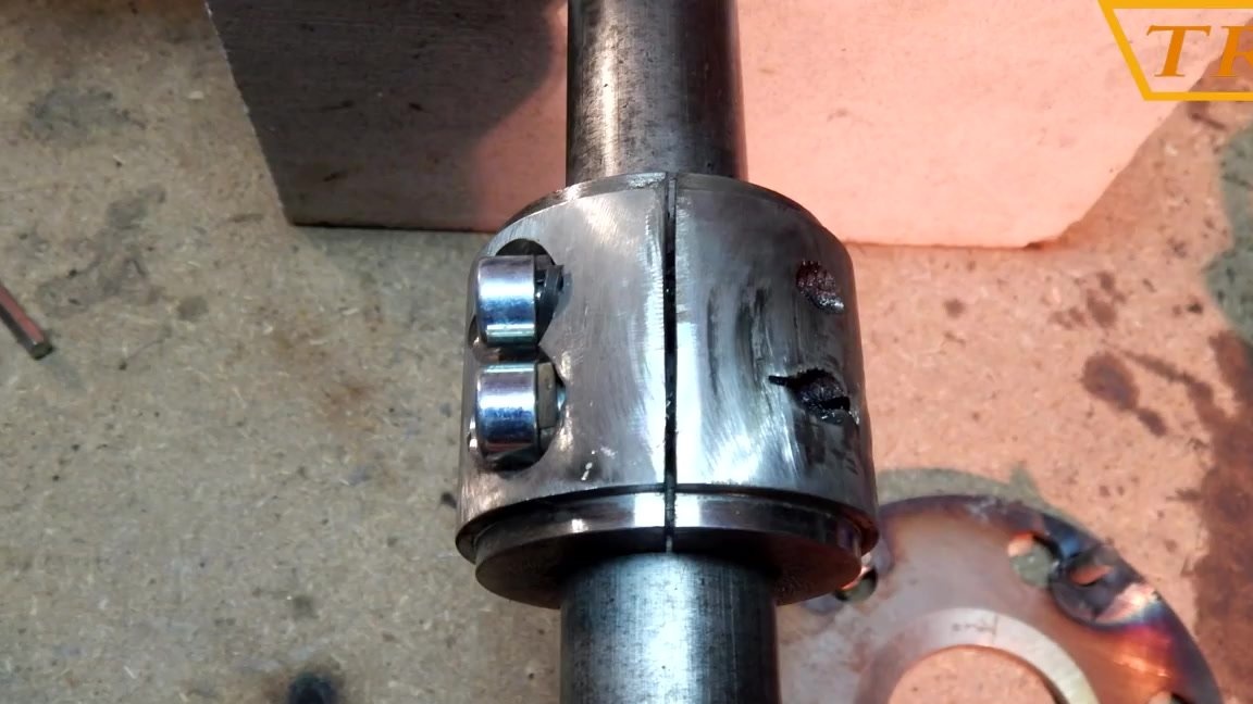
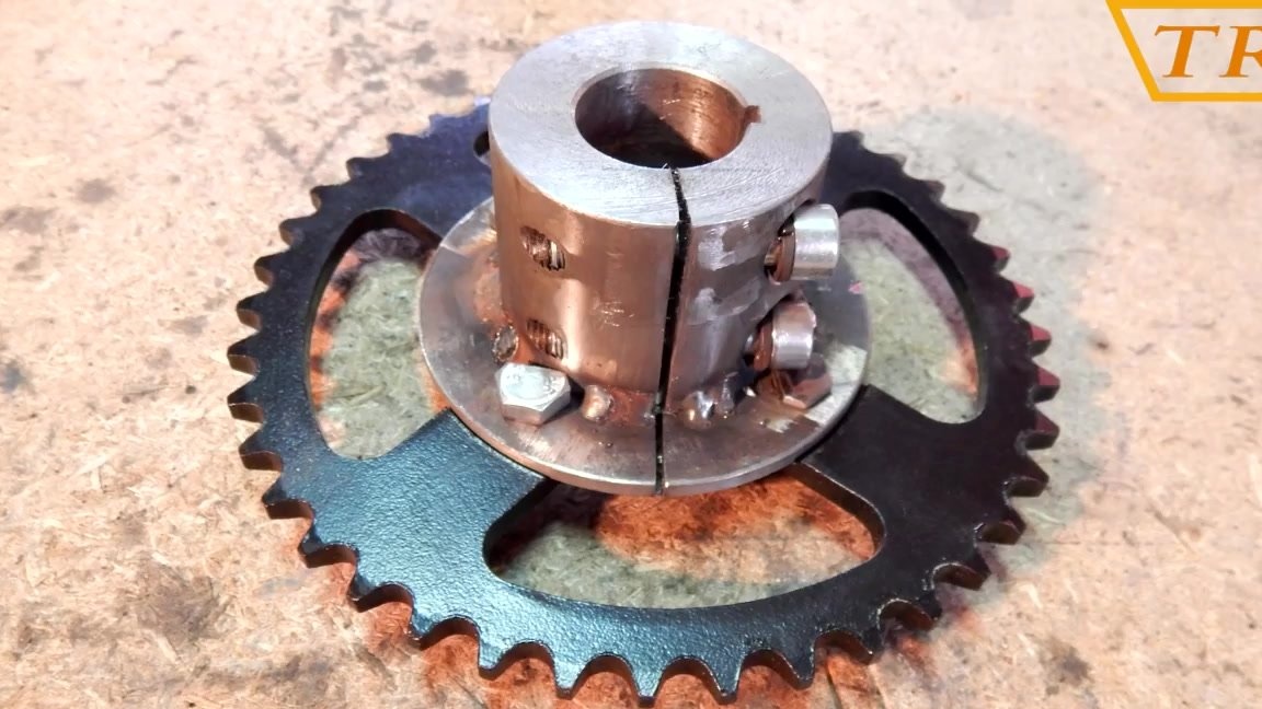
Now I collect all the bushings on the axis and fix them. At first I thought of assembling bushings on an axis with dowels, but then I refused and simply clamped the bolts on the bushings. Since the inner part of the sleeve was machined exactly under the diameter of the axis 30 mm, the connection turned out to be very tight, which prevents the bushings from turning.
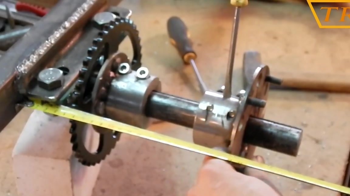
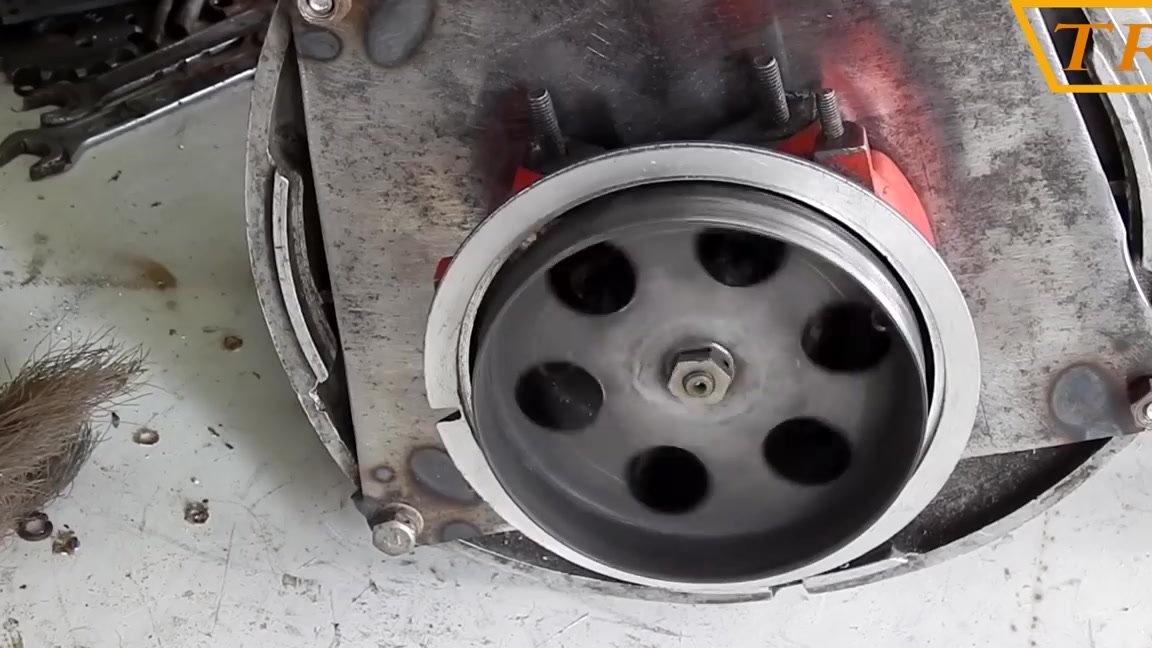
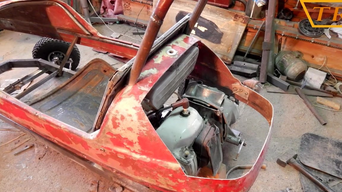
Then I put the chain on the sprockets, put the gearbox on the frame, and weld the box to the frame.
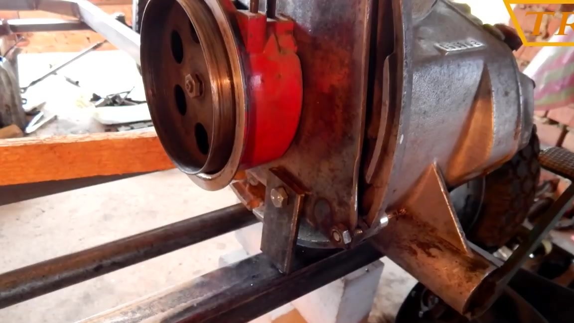
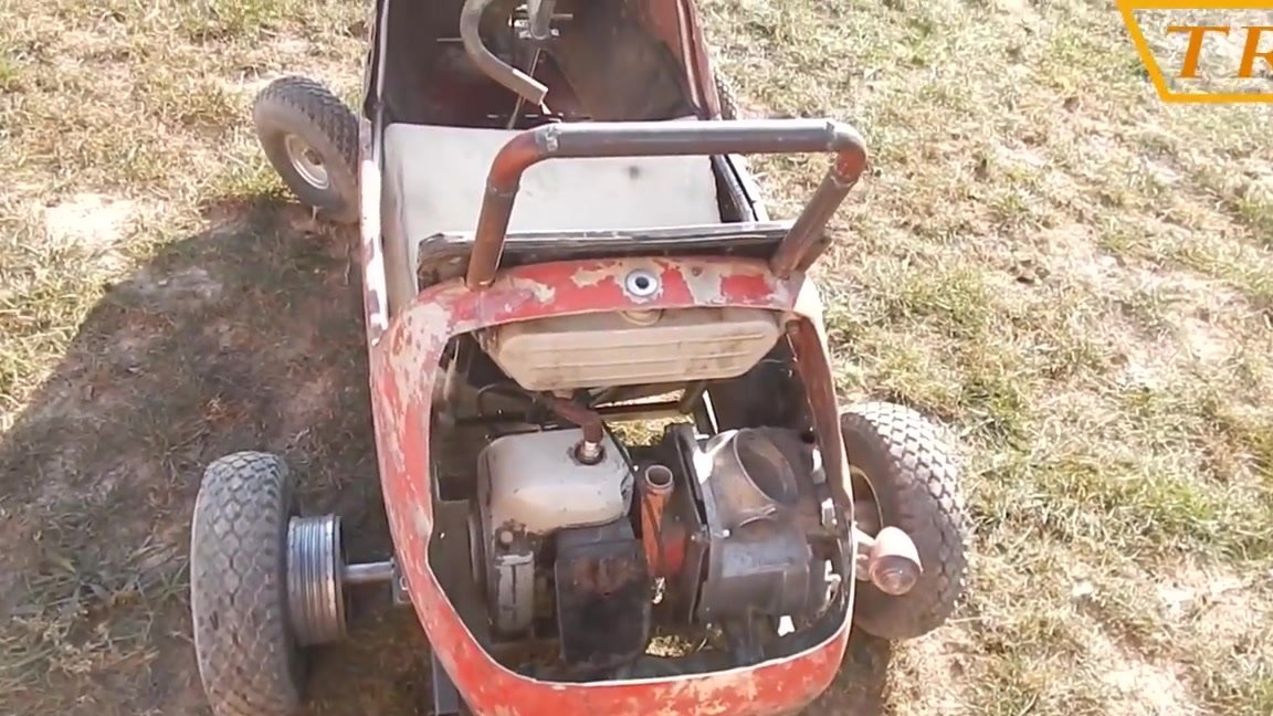
Now that the gearbox is mounted on the frame, the engine is joined to it and I weld the engine to the frame.
Video instruction!
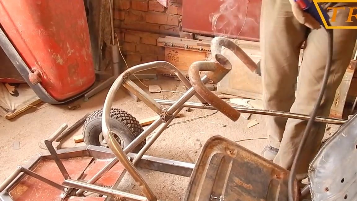
Step Five: Body Mount
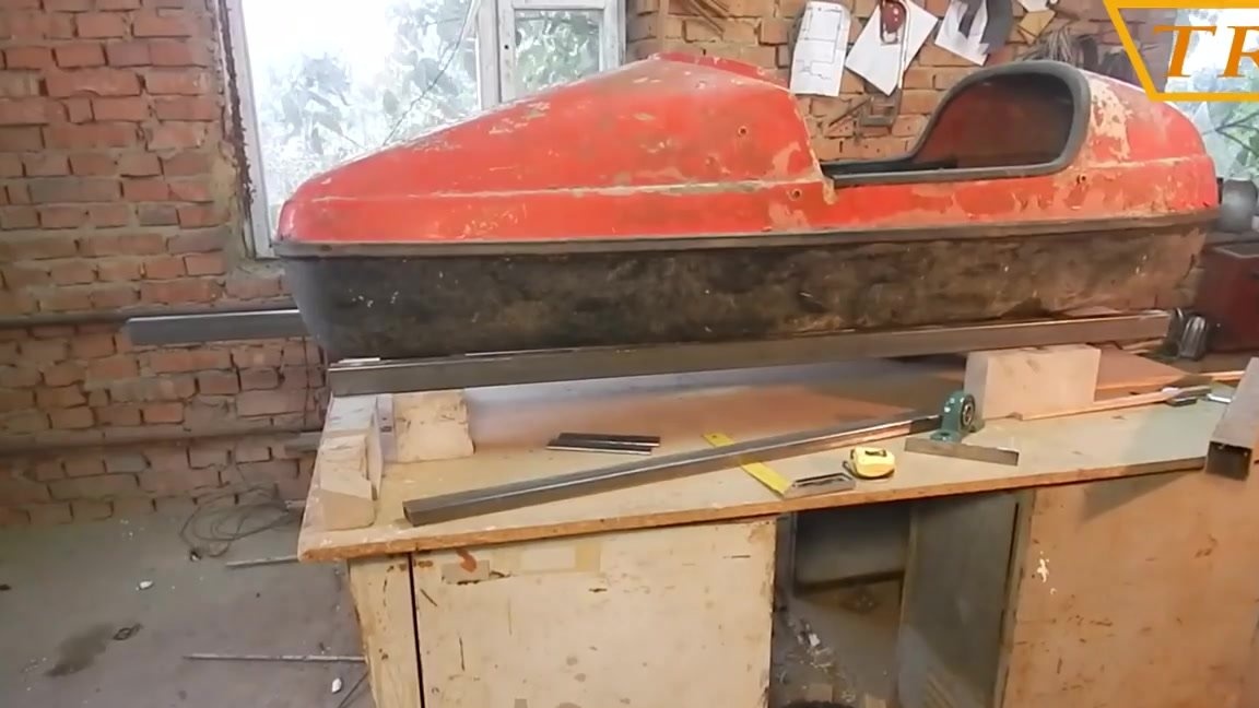
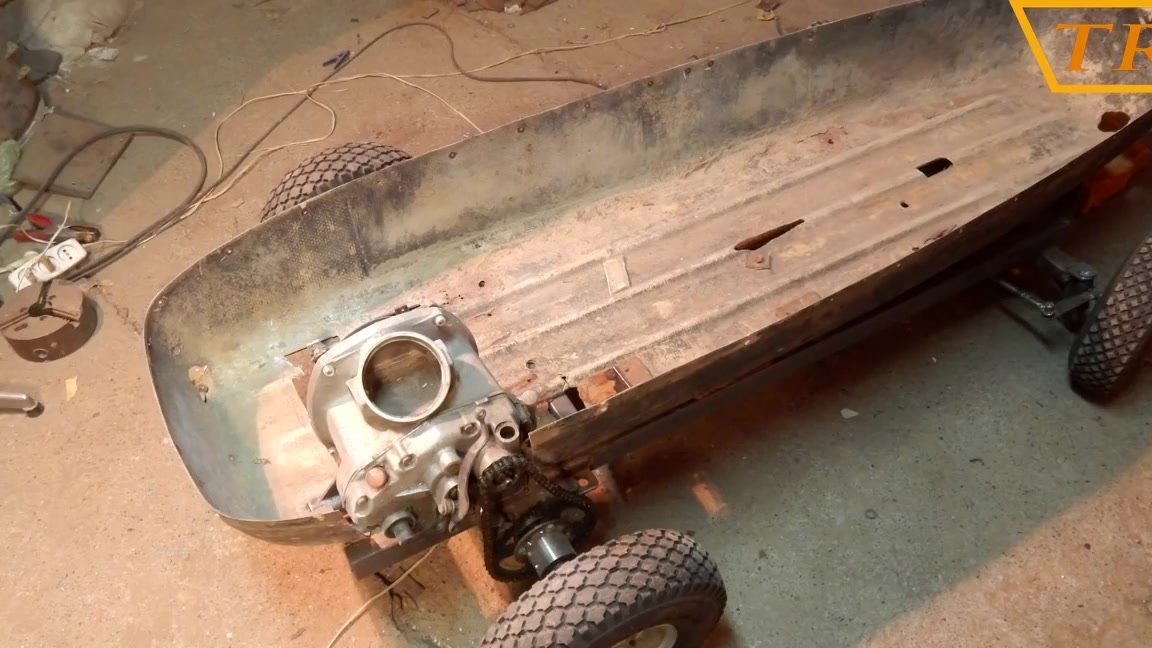
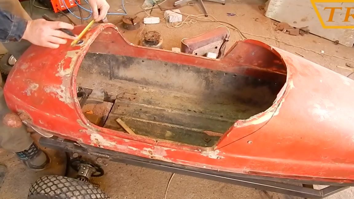
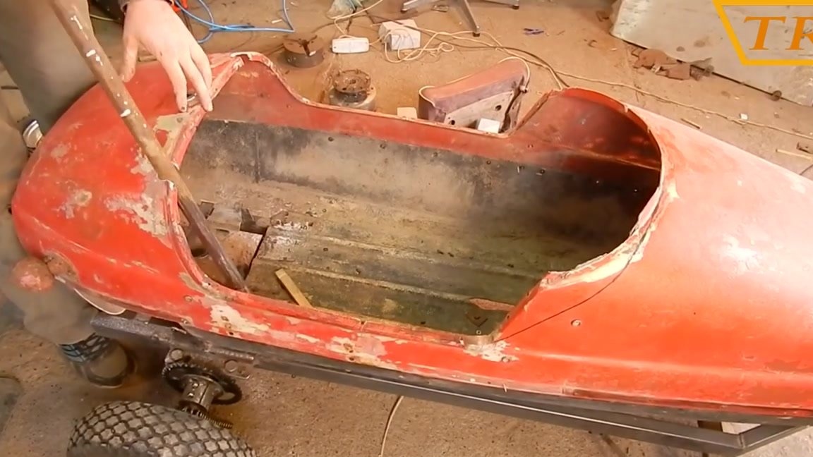
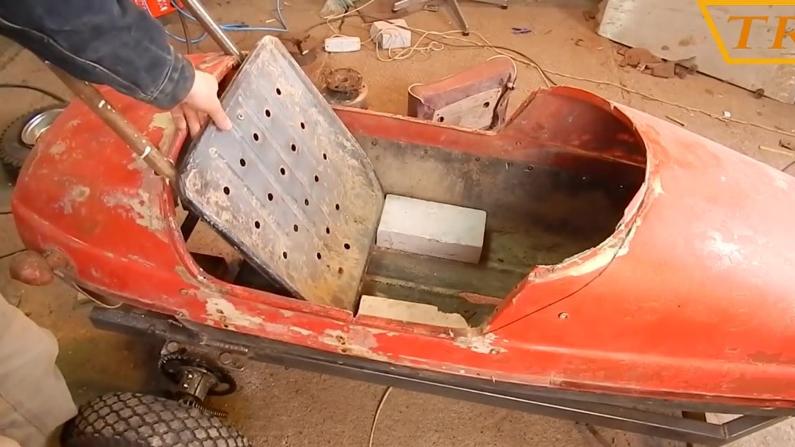
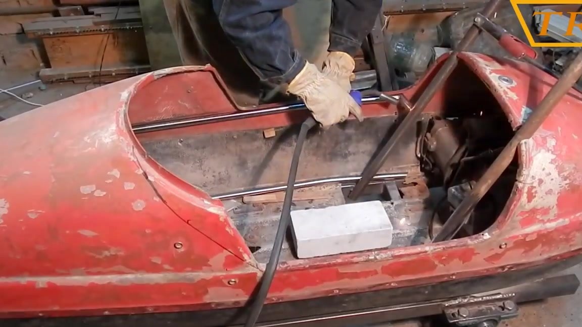
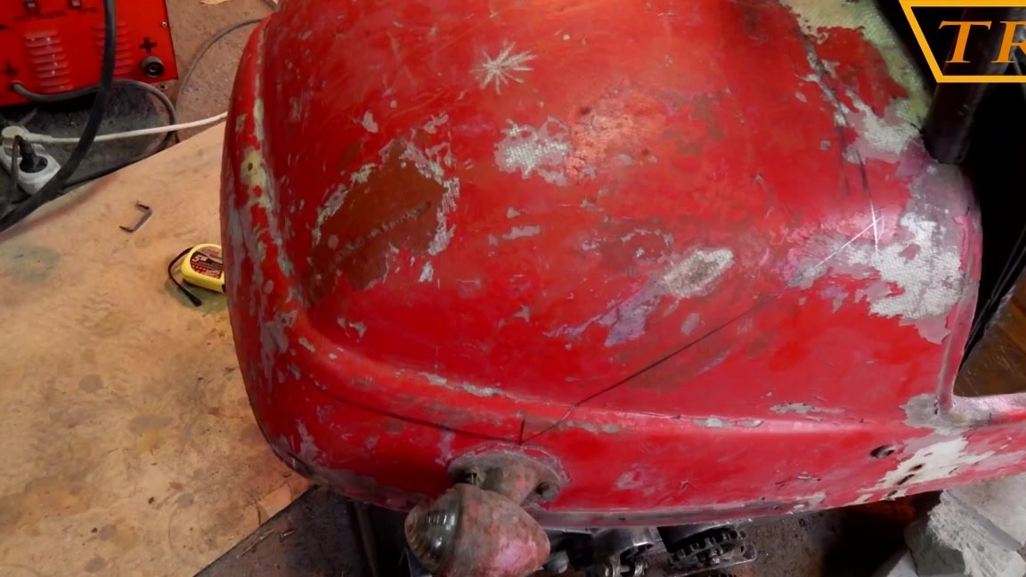
The body of my machine will be an old cradle from a Java motorcycle stroller made of fiberglass. And now it's time to install it on the frame. The cradle is assembled in two parts and connected in the middle. I divided it and put the lower part on the frame.
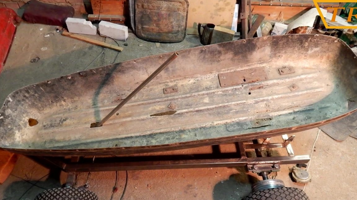
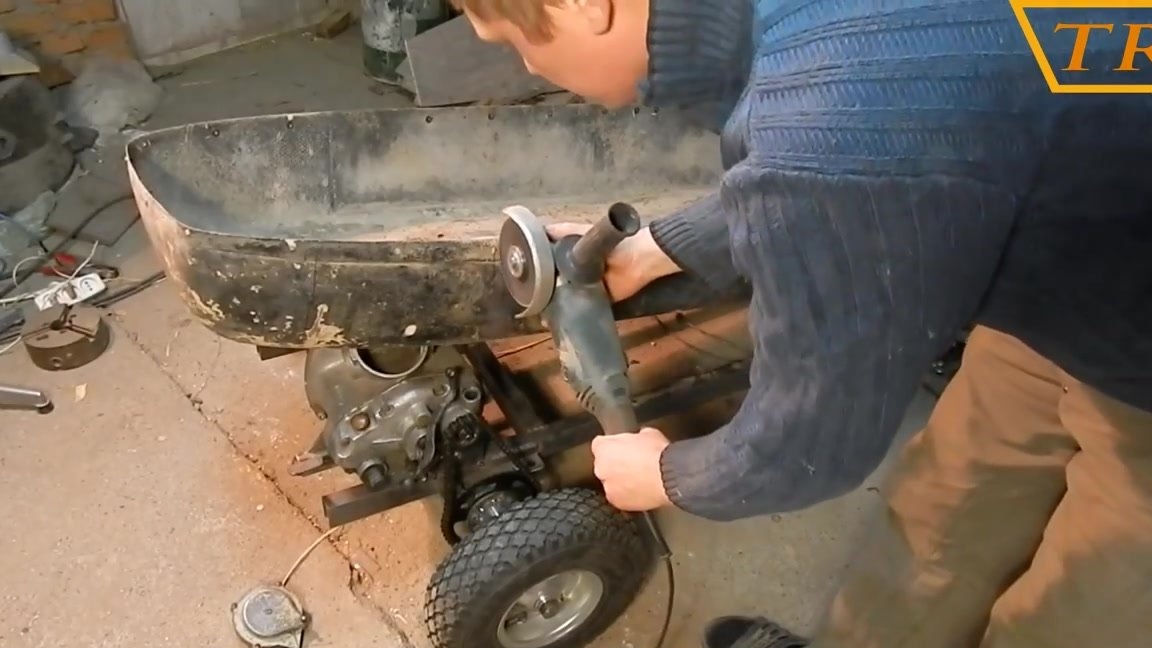
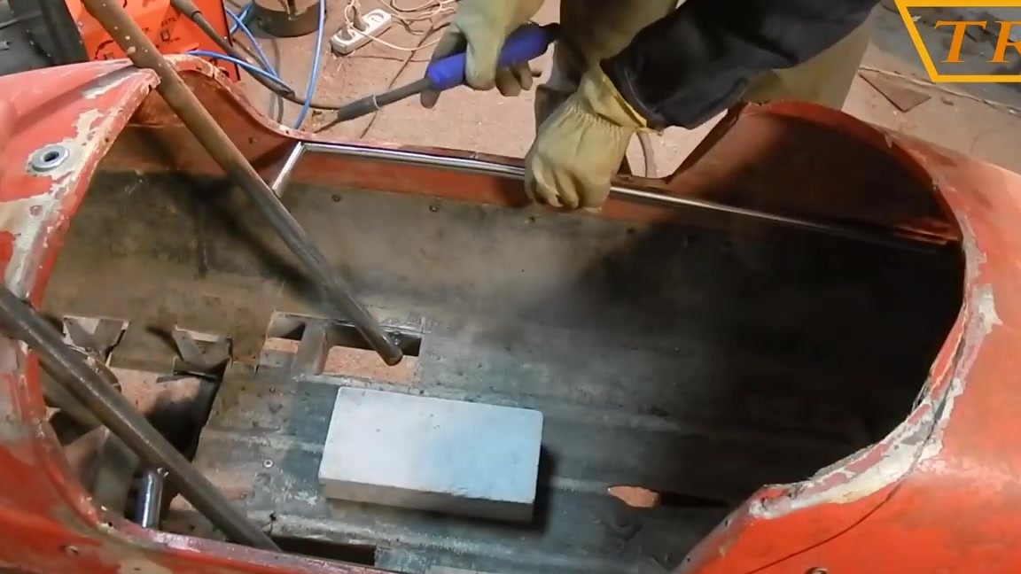
After fitting, I cut the grinder in the right places so that the cradle sits on the frame.
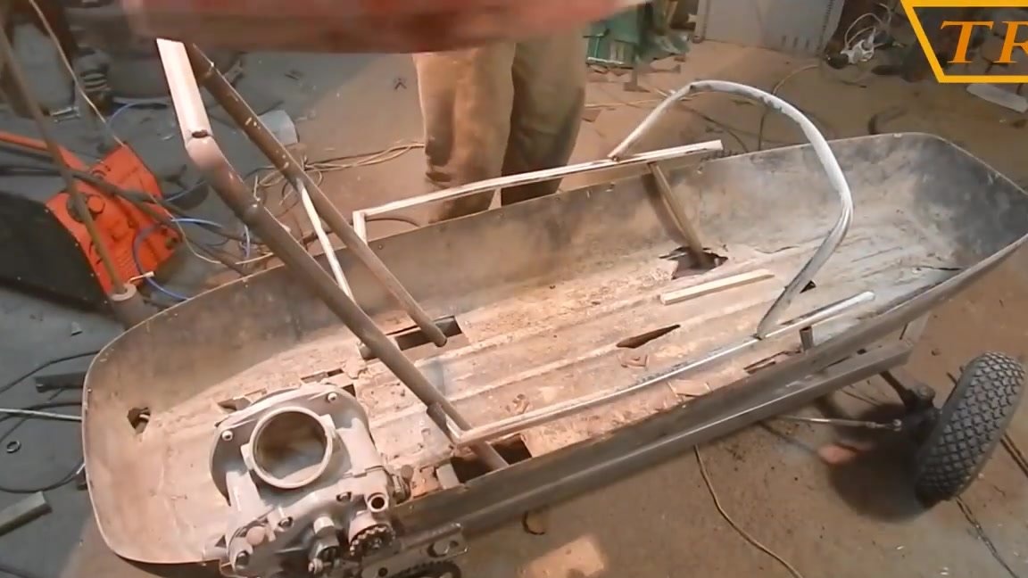
I put the top of the cradle and make a frame out of the pipe for attaching the seatback.
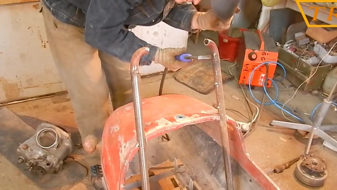
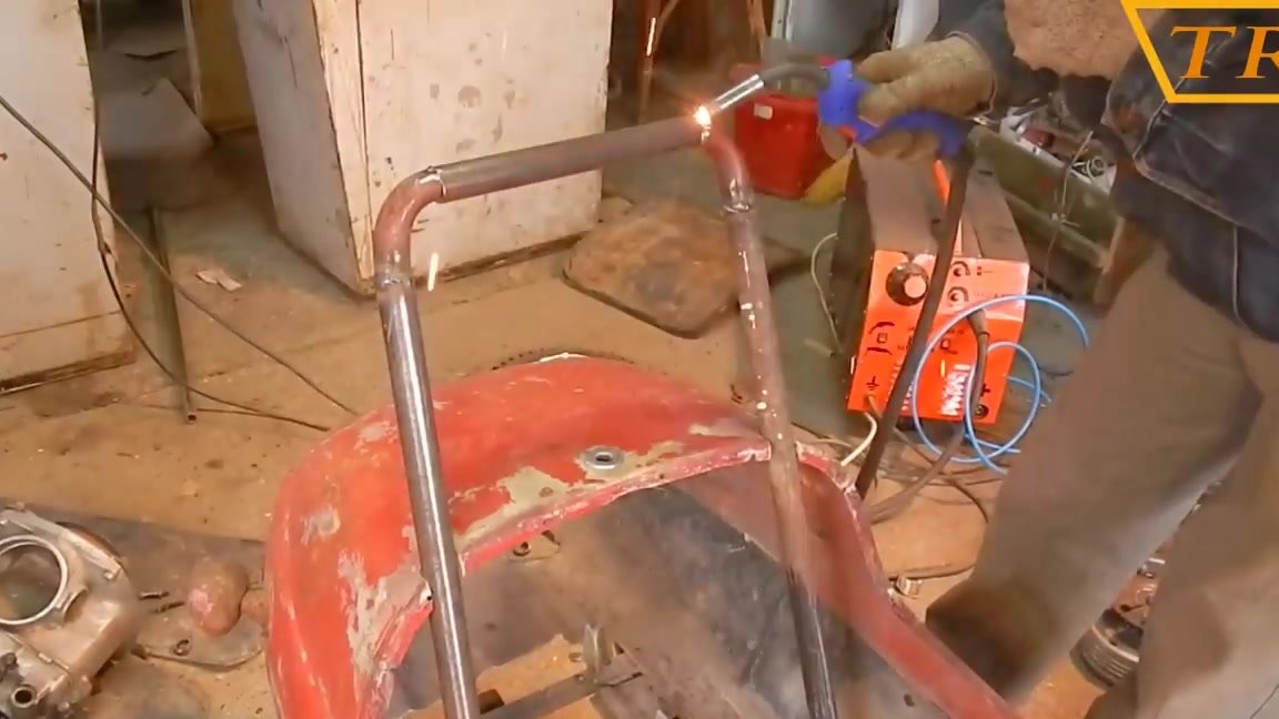
I weld a small spacer from a thin tube on which the top of the cradle will rest.
Then I cook the inner frame on which the top of the body will hold.
Now I install the front brake and gas pedal.
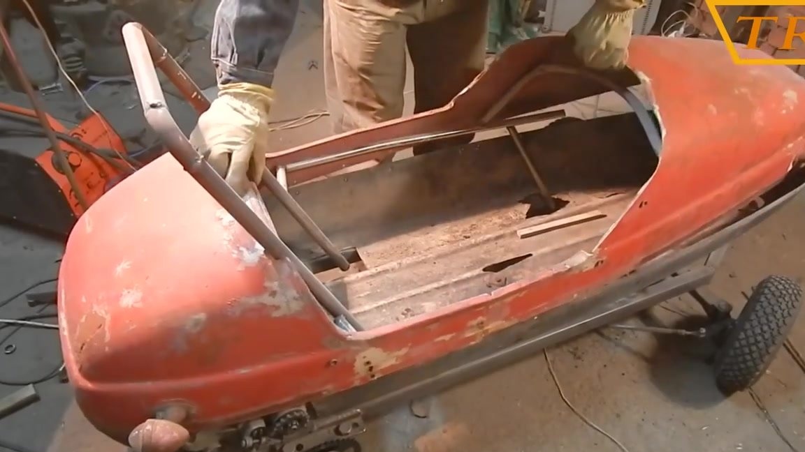
In the underbody I cut out the excess.
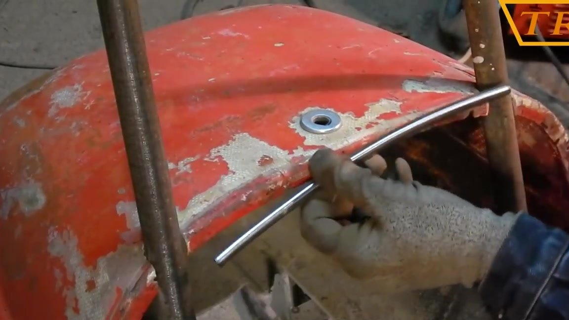
I bend the front frame in the shape of a cradle and weld all the seams.
Now I expose the seat at an angle convenient for sitting and weld the mount to the frame.

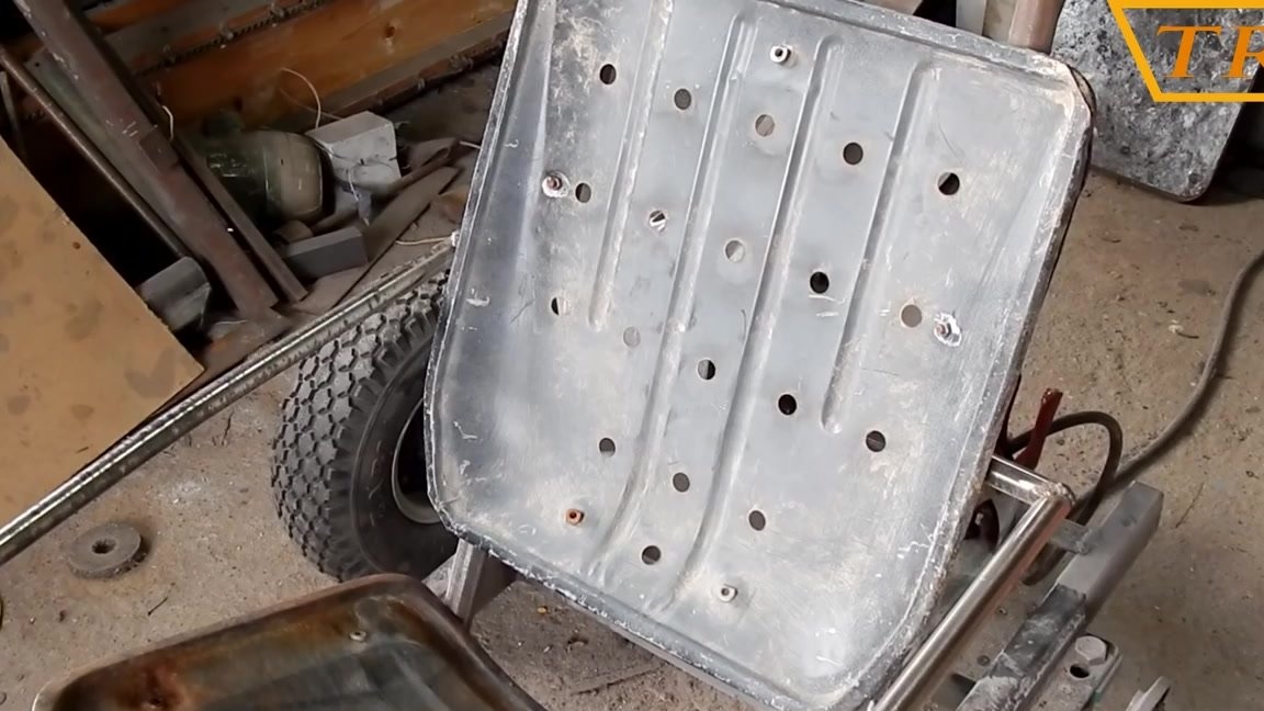
In front of the frame under my feet I fasten a couple of pieces of tin.
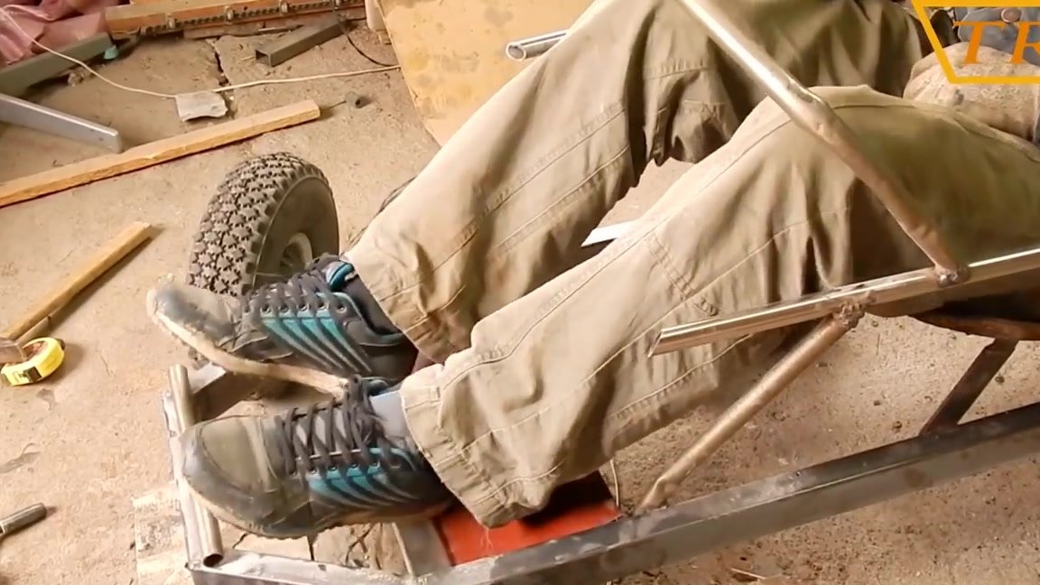
I connect the throttle to the pedal, and pull the return spring.
I put the steering shaft in place and weld an additional mount on the frame.
Steering wheel set from some plane, just welded tightly to the steering shaft.
I mark the back of the top of the body, and cut out the trunk lid.
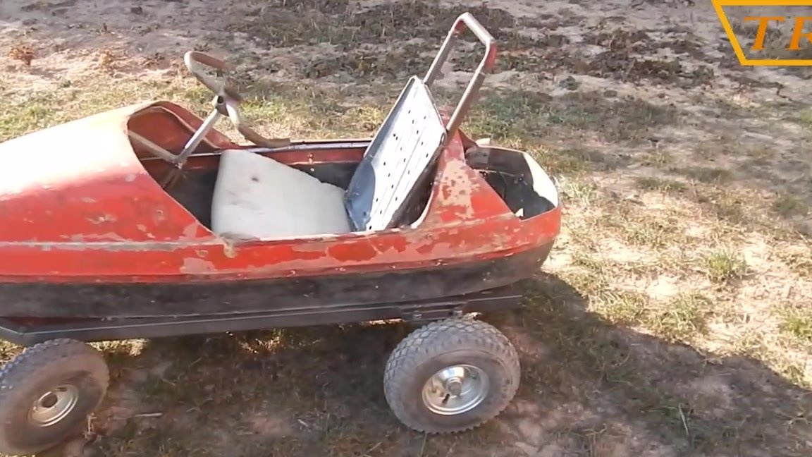
Having collected everything in a heap, such a machine turned out.
Video instruction!
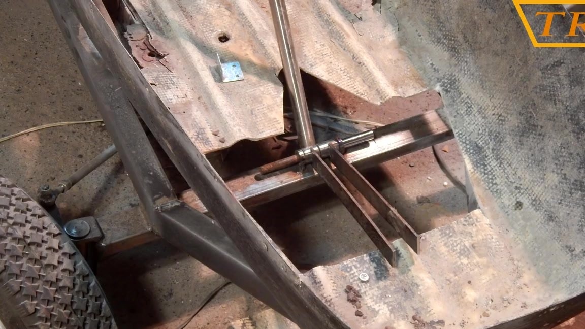
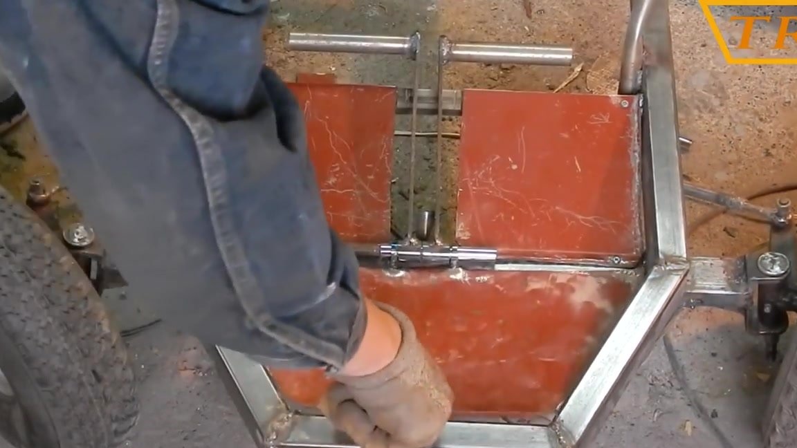
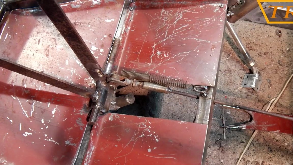
Step Six: Brake and Gear Shift
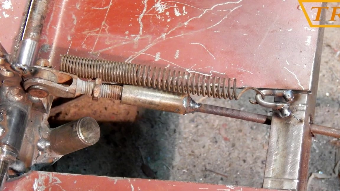
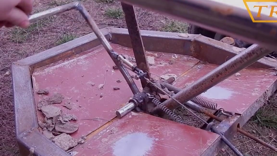
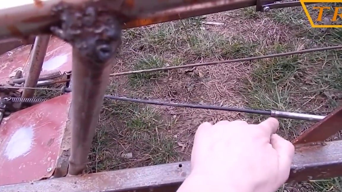
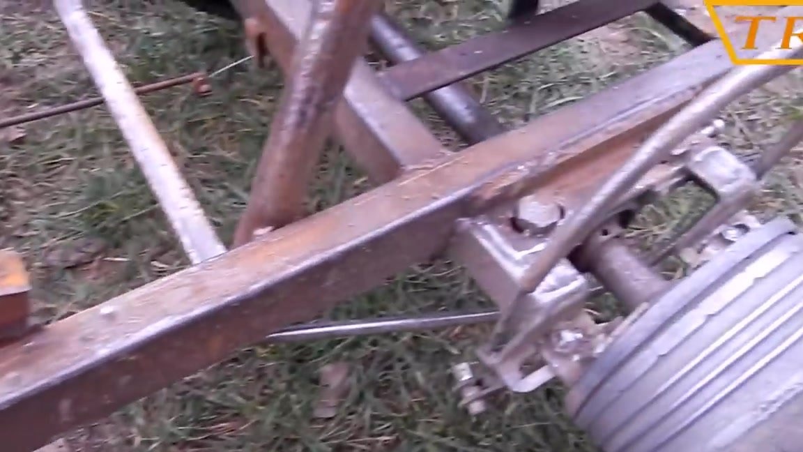
The gear selector is made in the form of a handle and is assembled from several rocker arms of different directions and the axes on which they are attached, as well as several rods and a shaft.
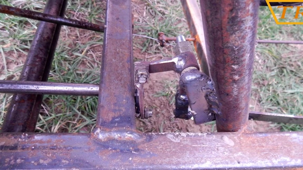
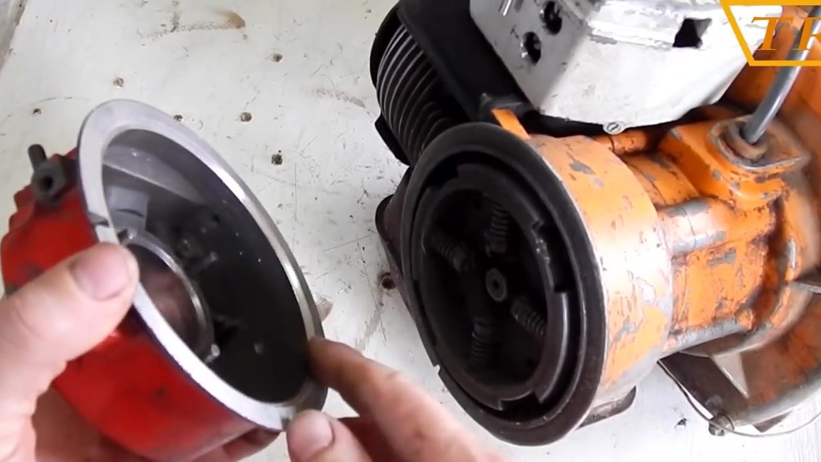
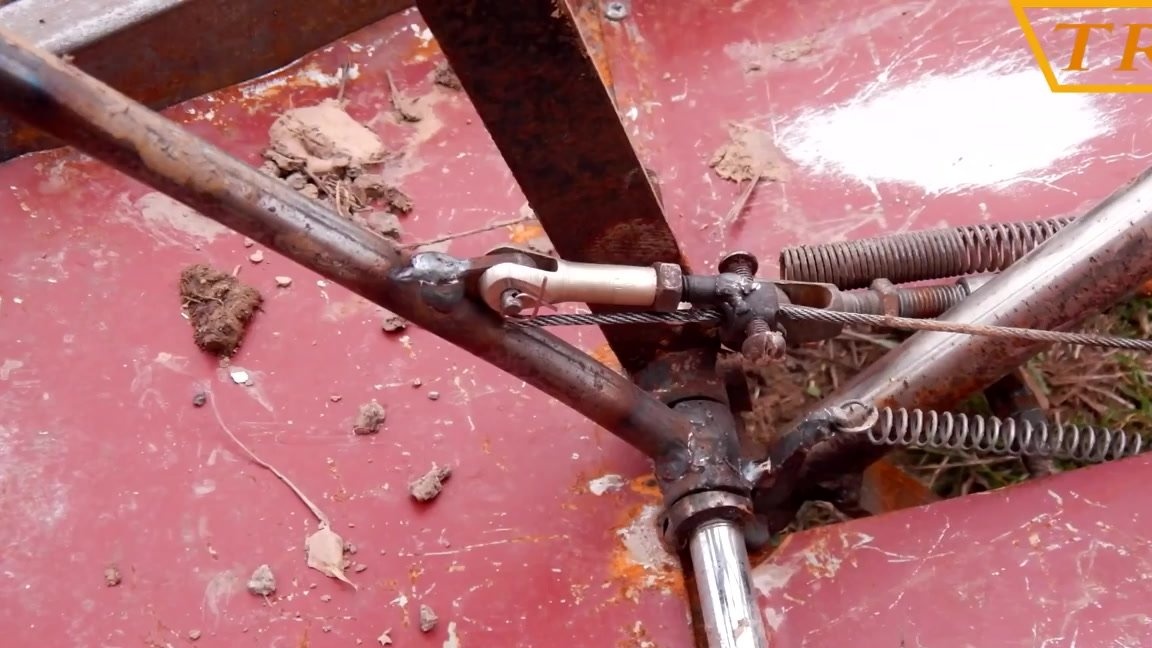
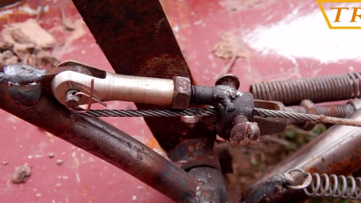
The brake is made from the drum of the front wheel of a motorcycle Minsk.The inside of the cover with pads is machined to the diameter of the rear axle. The cover is screwed to the mount welded to the frame.

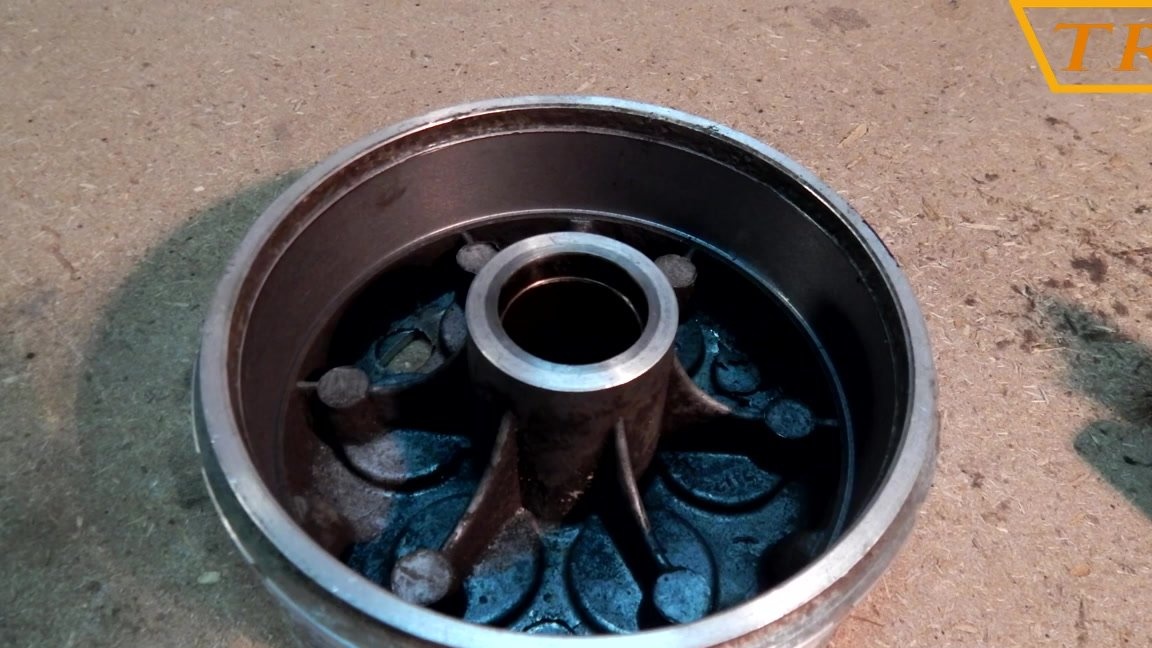
The brake is activated by depressing the pedal, transmitting force to the pads through the cable.
Video instruction!
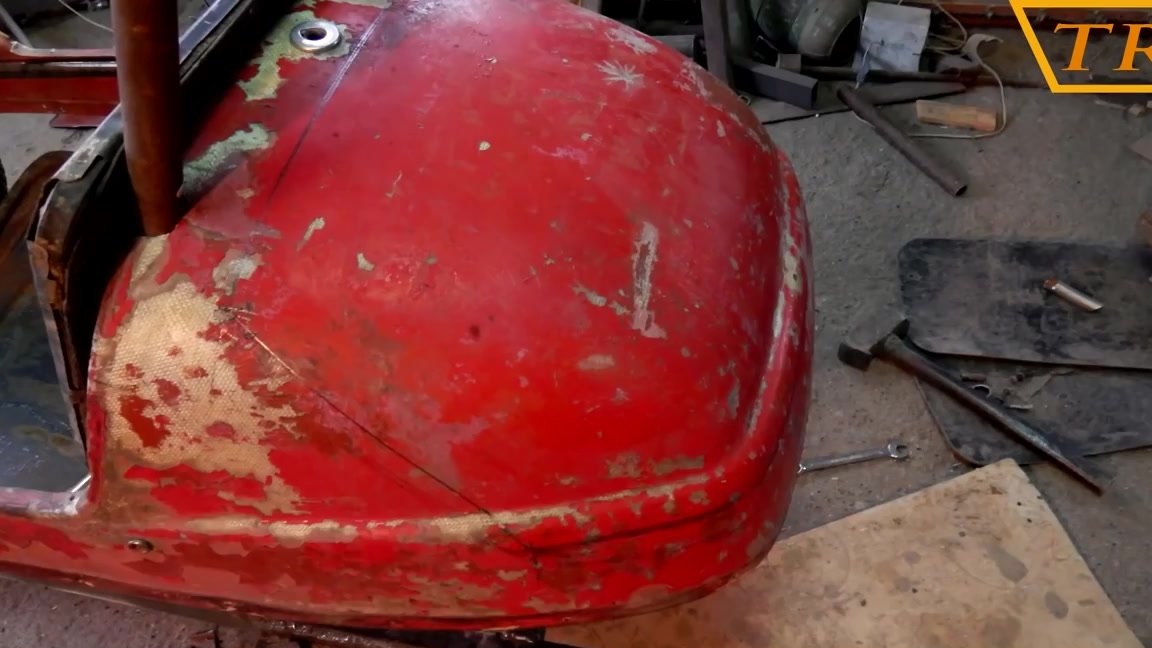
Conclusion
Now, after the final assembly, you can paint everything and give the machine a more aesthetic appearance. Unfortunately, I did not finish doing everything that I planned on the typewriter. This design is not quite suitable for driving on rough terrain and at first I froze the project, and later completely altered it to buggy. Now you can safely proceed to the test.
In conclusion, I want to say, if you have a child and have a desire, do something similar together. In my childhood, dad and my brother made a three-wheeled bicycle, and you can’t even imagine how much joy, positive emotions and impressions of such a technique were. Many years passed, and memories remained for life. Believe me, if you do something like that, your child will never forget this either. Of course, now there are many toys and equipment of such a plan for sale, but made do it yourself will be remembered forever!