
If you were looking for a universal dc-dc converter circuit, then this article is for you. Today, together with Roman (author of the YouTube channel "Open Frime TV"), we will assemble a Sepic converter.
If you use the search, then I think the first in the list will be the video of the famous video blogger AKA KASYAN (YouTube channel “AKA KASYAN”) on the assembly of up / down dc-dc converter.
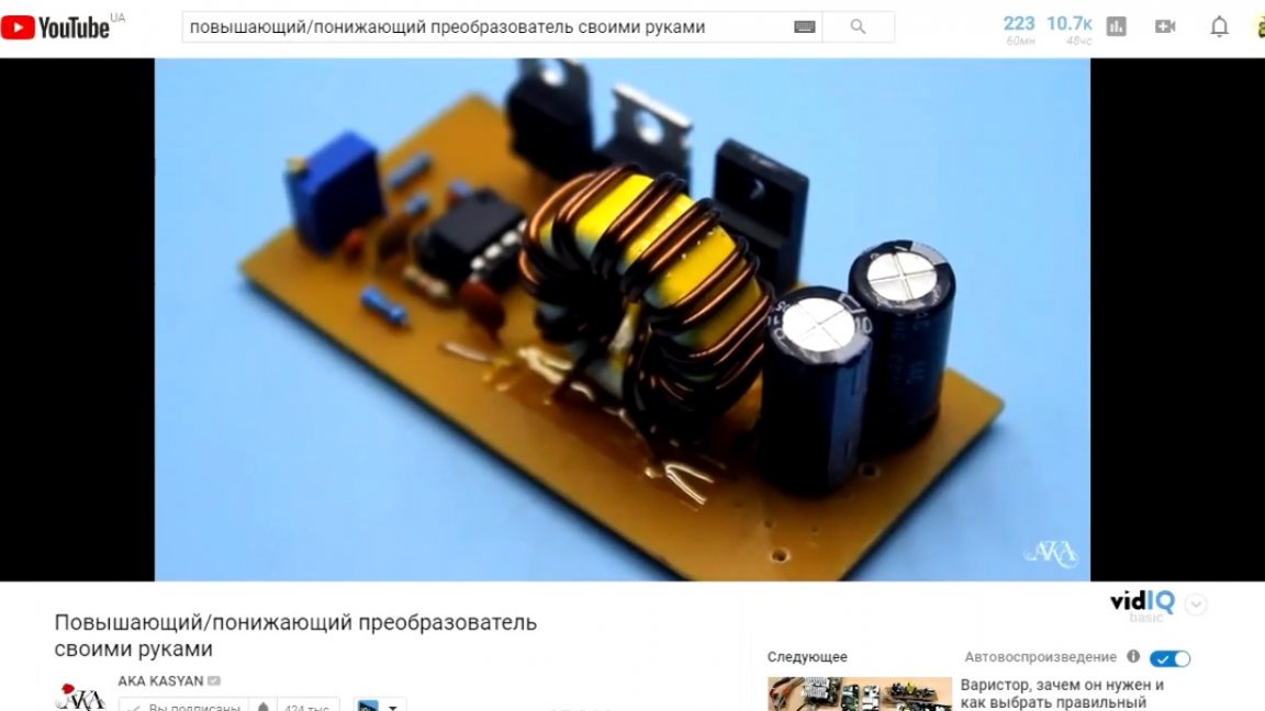
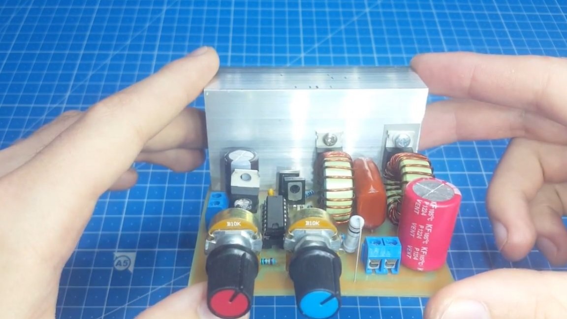
Only there is a circuit with one inductor and there is no current regulation. The version of the novel is collected on Sepic topology, we will familiarize ourselves in more detail later. Now let's figure out why such a converter is needed.
Let's start with the characteristics:
Input voltage from 10V to 25V;
Output voltage from 0 to 30V;
The output current is up to 2A (there are some features here, we will affect them when calculating the inductor).
As you can see from the characteristics, such a converter can be used in car to increase or decrease the voltage of 12V. You can also connect such a home-made dc-dc converter to the output of a computer power supply and receive different voltages from it without alteration.
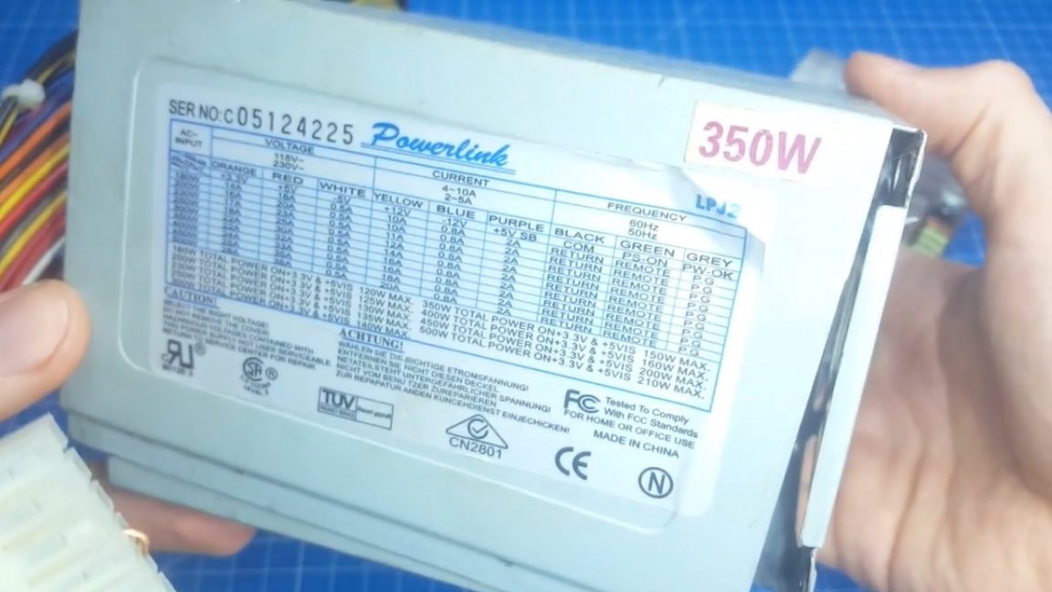
Well, or you can take the power supply from the laptop and again receive any voltage at the output. It is very convenient, no need to worry about the supply voltage.
Now go directly to device diagram.
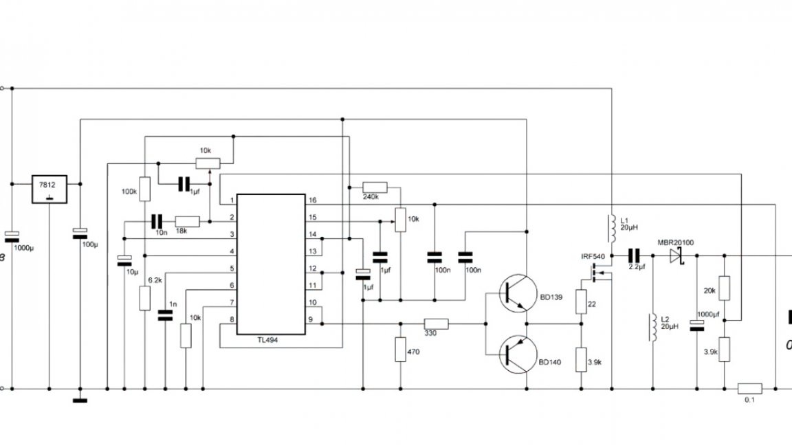
Here we all know tl494, she is already many years old, but she still does not give up her position.
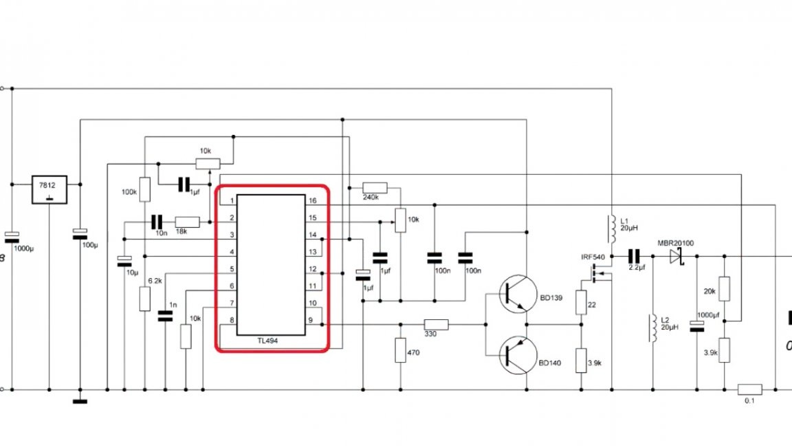
From the very beginning, the author wanted to make a dc-dc converter on the UC3843, but they turned out to be defective, they were something else, but the author could not achieve normal work.
Plus, if you adjust the current, you need to put a second shunt, and this reduces the final efficiency of the device.
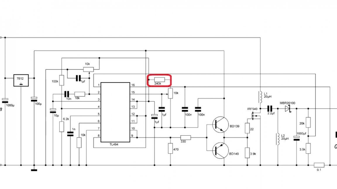
Roman (the author of today's homemade product) did not come to this scheme right away, but after talking with the YouTube author of the RED Shade channel, which suggested in which direction to think. And here is the final diagram of the device:

It has an adjustment of voltage, current, and also a field driver is installed. With it, the heat decreased slightly.
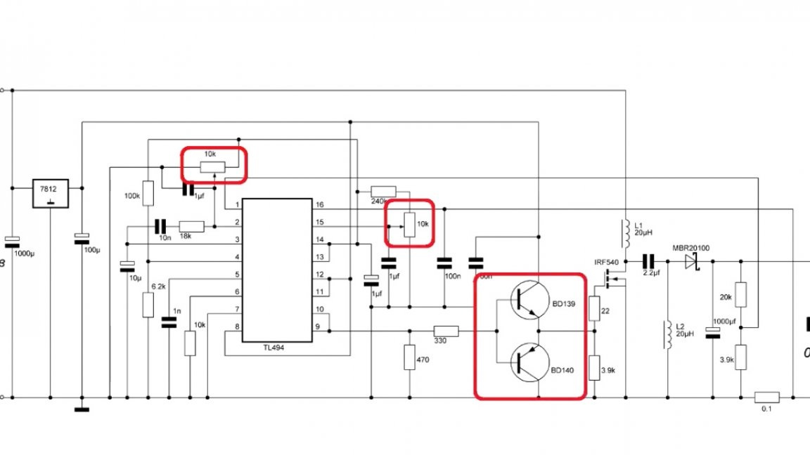
You can also see that the maximum width of the output pulse is limited, since at maximum filling the circuit went into an incomprehensible mode, ate a lot of current, but the voltage dropped at the output.
The maximum output voltage is 30V.

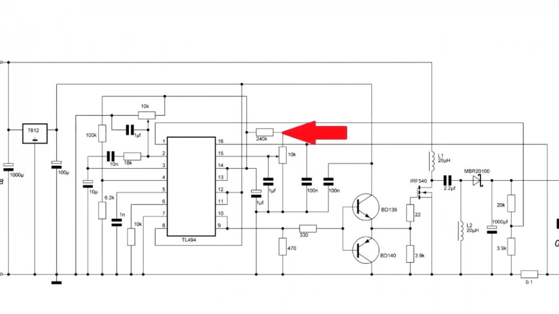
If you need more, you will have to recalculate the value of these resistors:
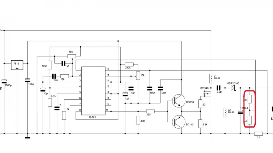
Moreover, in such a way that at the desired output voltage at the divider point was 5V.
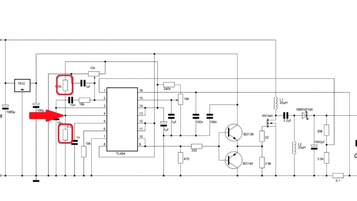
We also have limited current, it is 2A. If you need more, then you need to recount this resistor:
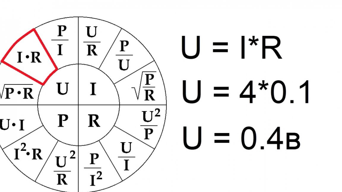
It’s already a little more complicated. First you need to find out how many volts will fall on the shunt.
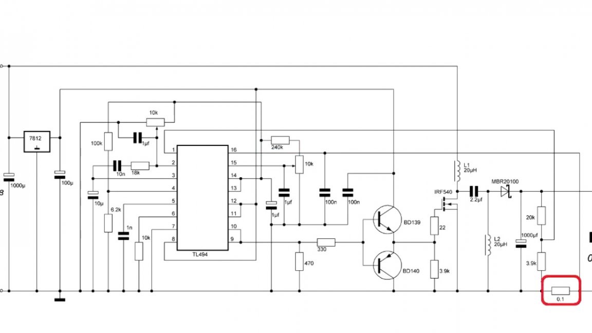
For example, we need a current of 4A. Then we look, at such a current, 0.4V drops on the resistor.
Ok, now we recount the resistor. We need that at the point of division of the variable resistor and constant, the voltage should be 0.4V.
To do this, go to the online calculator and start picking up a resistor.

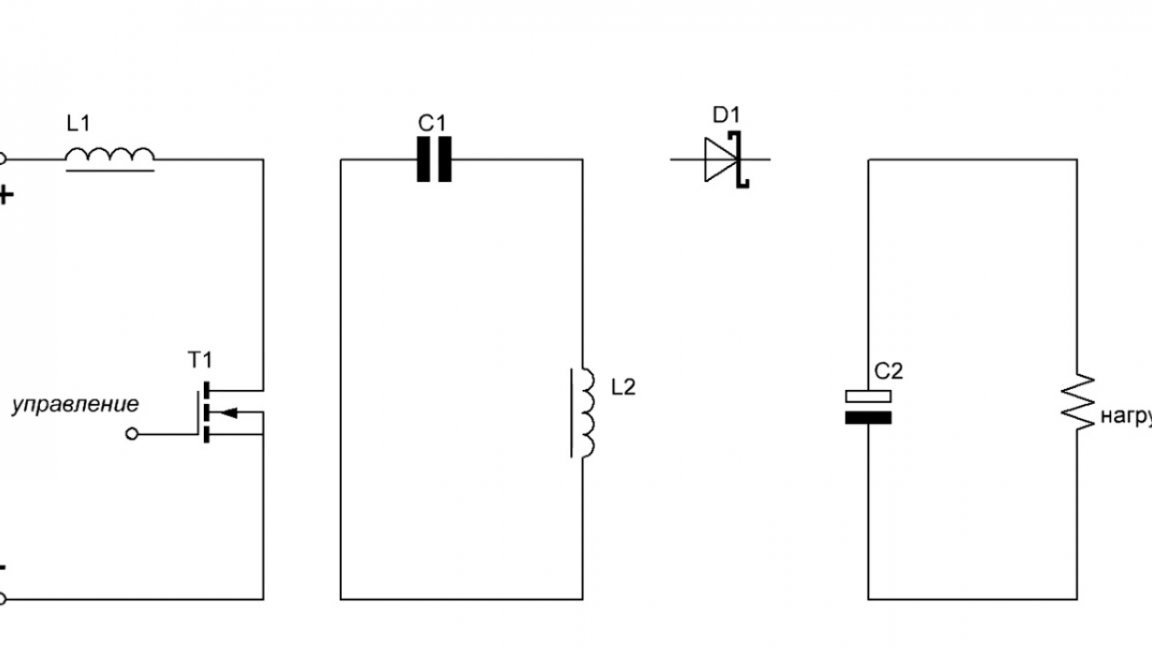
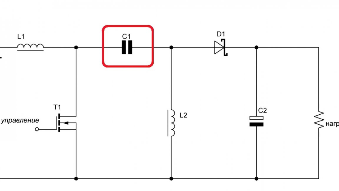
As you can see, this is not difficult. Now let's talk about how it all works. Reference point - the device is turned off.
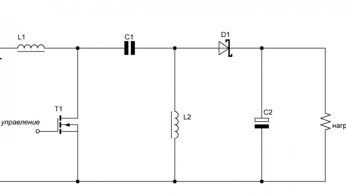
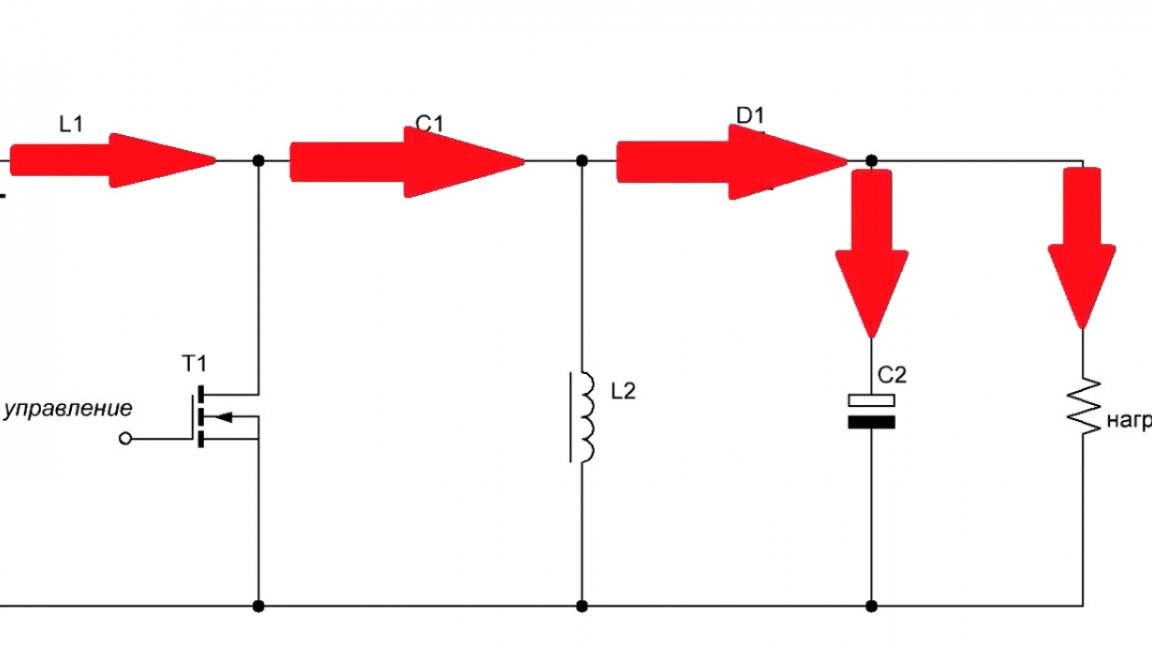
So, we are giving food. The key is open, which means that current flows through the inductor, capacitor and diode directly into the load and output capacitor.
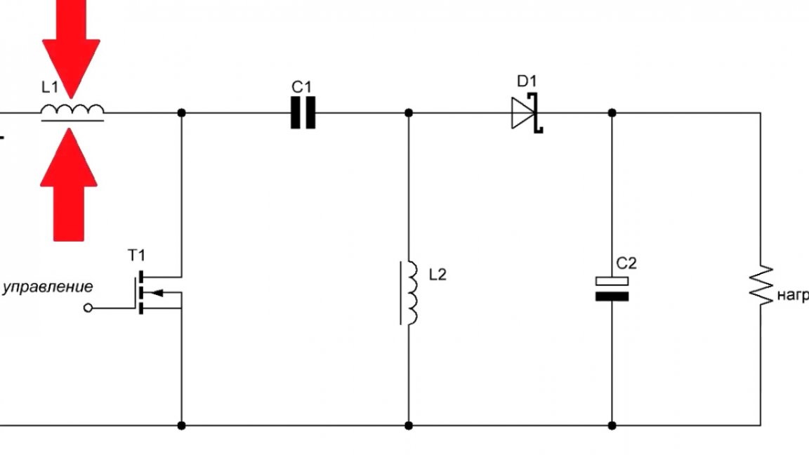
Then the key is locked.
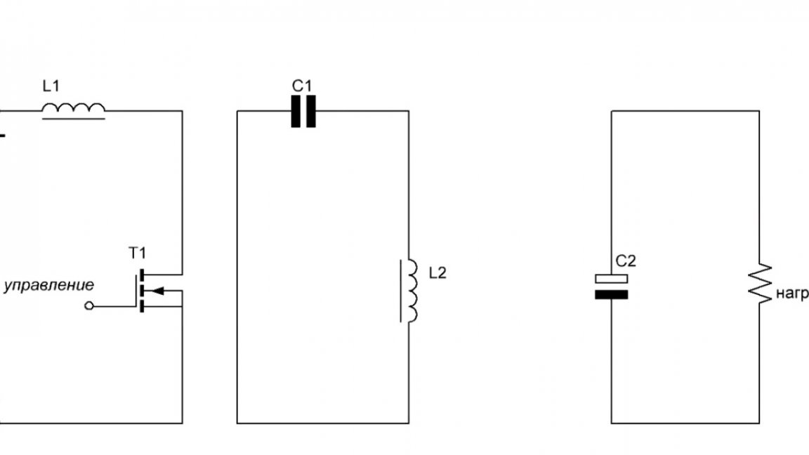
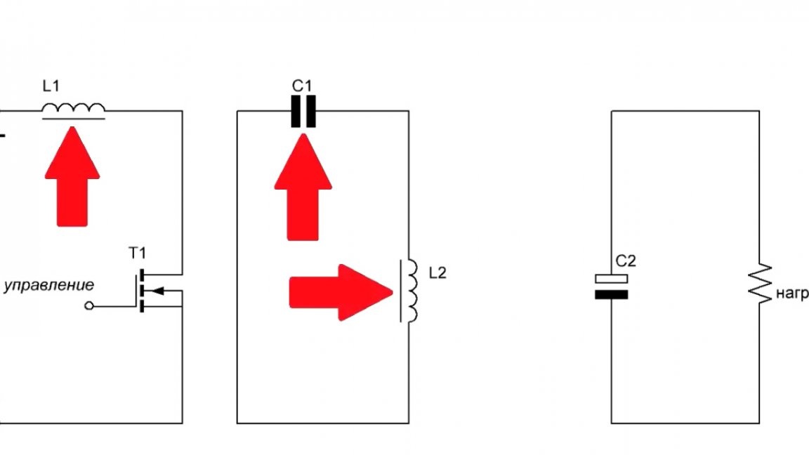
At this moment, energy is accumulated in the coil L1. The feed-through capacitor was charged with the supply voltage, and since after the key is closed, it turns on in parallel with the inductance L2, it charges it.
The voltage with L2 cannot go into the load, since there is a diode and its voltage at the cathode is higher than at the anode.
Now the key is open again, and the voltage on L1 is added to the voltage of self-induction.
Thus, an increased voltage is already applied to the passage capacitor and the load.
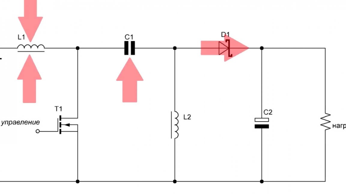
By changing the PWM duty cycle, we change the output voltage.
If the pulse width is sufficiently small, then the magnitude of self-induction is smaller, and, consequently, the output voltage decreases. The advantage of such a circuit over an ordinary step-up dc-dc converter is that a feed-through capacitor is installed here, which in case of a short circuit will not allow the circuit to fail.
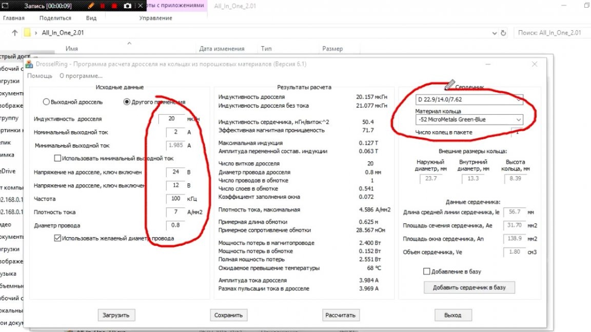
Now let's move on. As mentioned above, some components of the scheme must be calculated, since there is already a website with a ready-made online calculator, it makes life unrealistic.

As you can see, here you must enter your data.
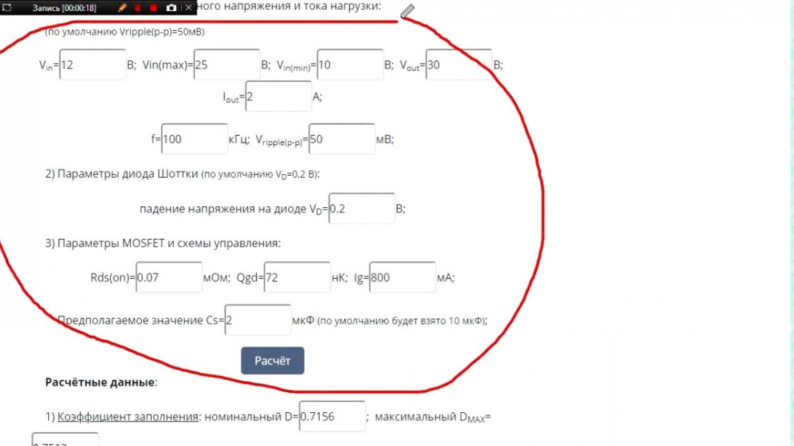
The author tried to calculate in the widest possible range and this is what happened:
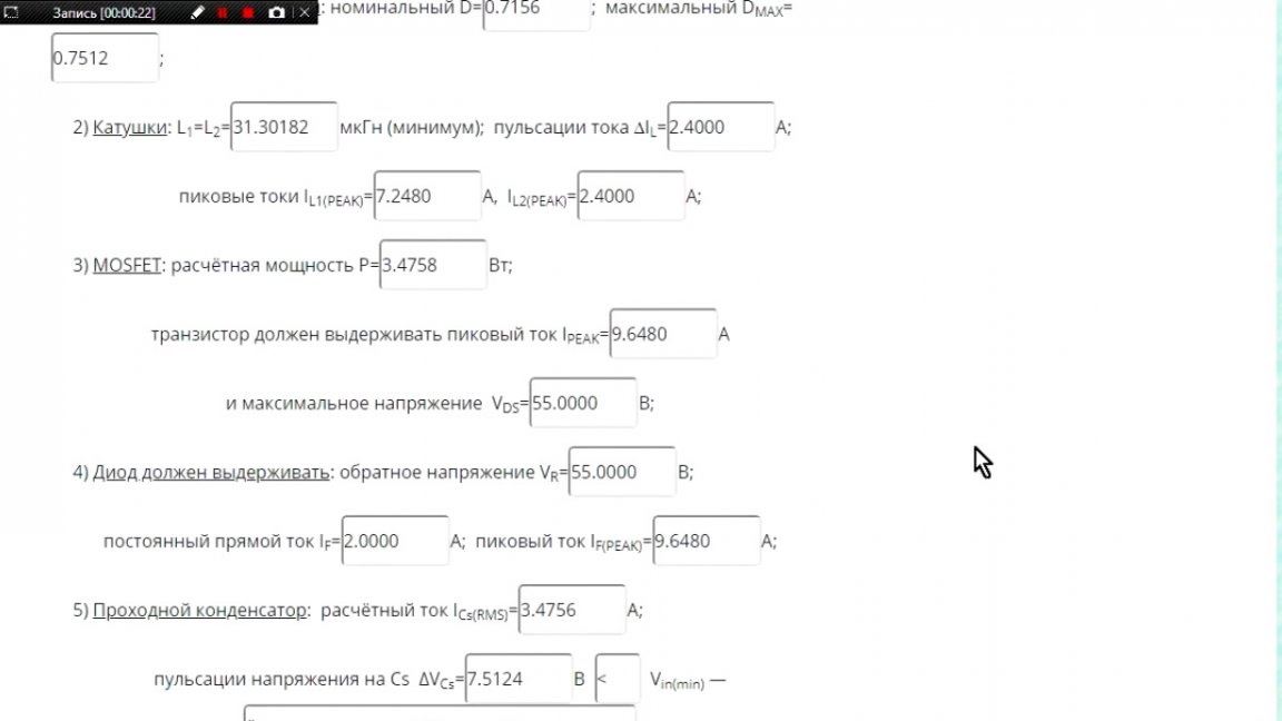
In the calculation, we got some inductance coils.
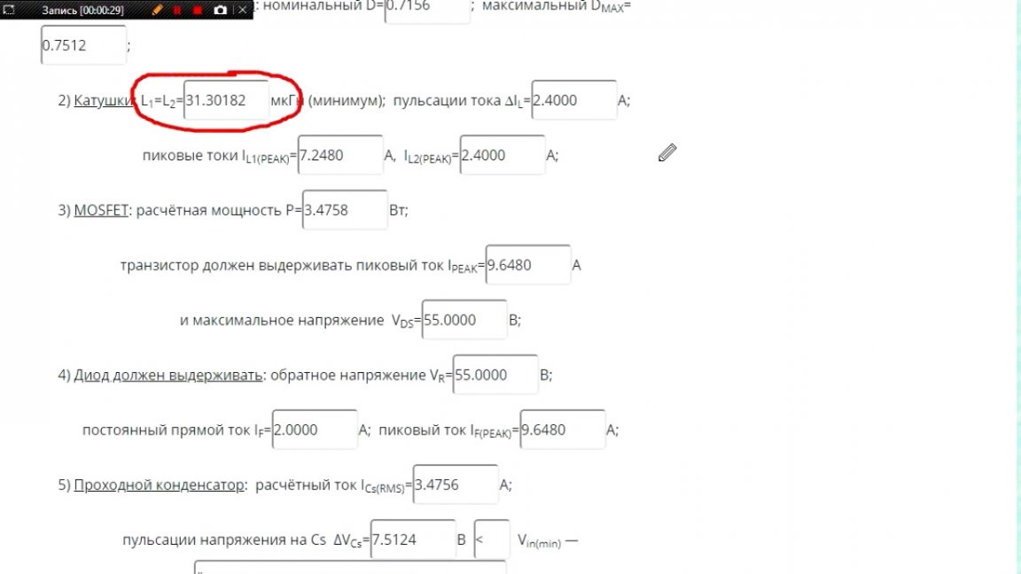
But how in real life can they be wound with the required inductance? The owners of the ESR meter will say that there is nothing complicated, you wind and look at the parameters.

But this ESR meter shows with a very large error, so the author suggests using the Old Man program.

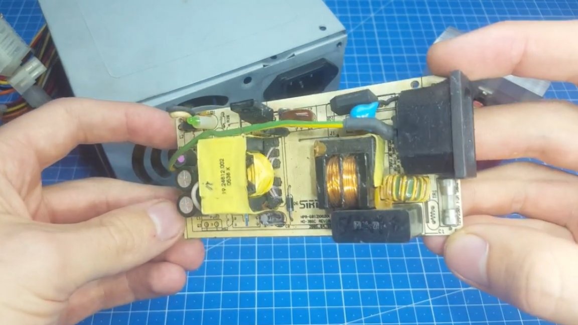
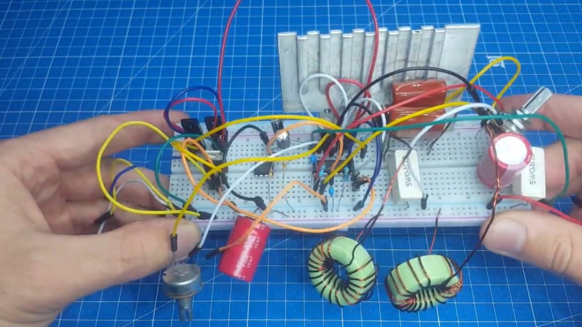
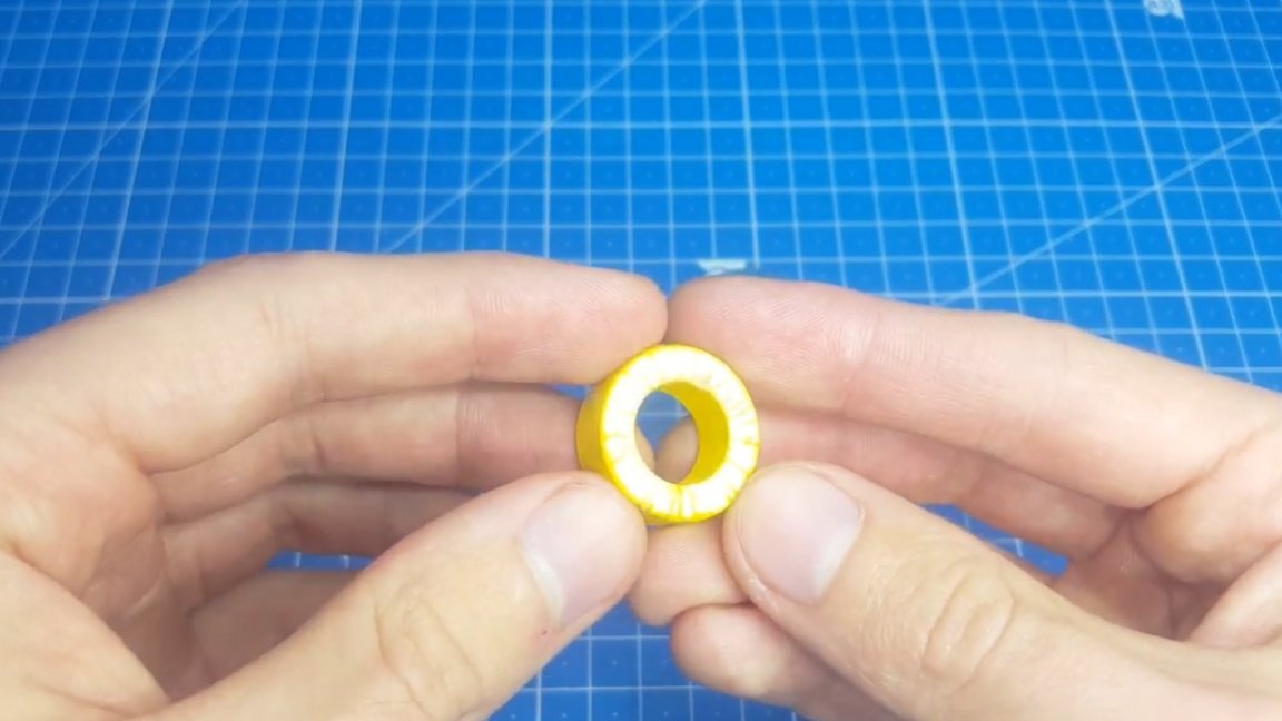
We enter all the necessary parameters in it, and also indicate which core we have. If there are none at hand, then we get 2 identical yellow rings from the computer power supply.
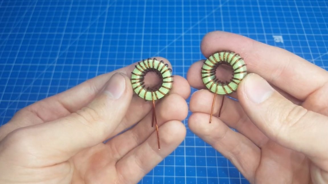
Well, it remains to reel our chokes, it will not be difficult.
It turned out pretty well. It would seem that all the difficulties are already behind, but no, there is still a PCB layout. The author spent a single evening on it in order to arrange all the elements as compactly as possible.
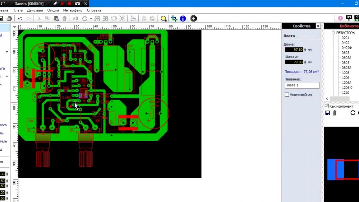
For mounting, you can make the board a little larger and add holes on the sides, but this is up to you.
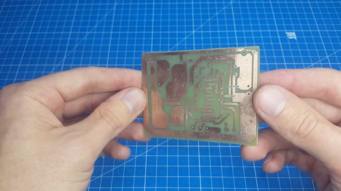
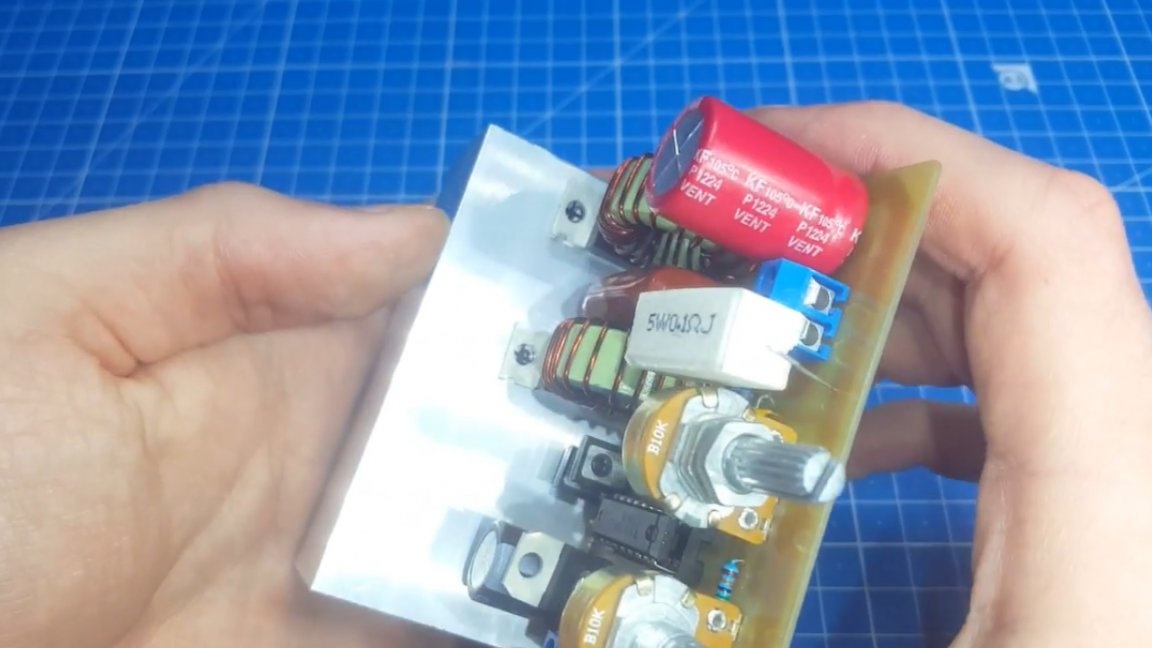
The board is ready, the holes are drilled, it is the turn of the sealing machine. There is one important point, it is necessary to raise the power elements above the board, since then it will be impossible to get a screwdriver.
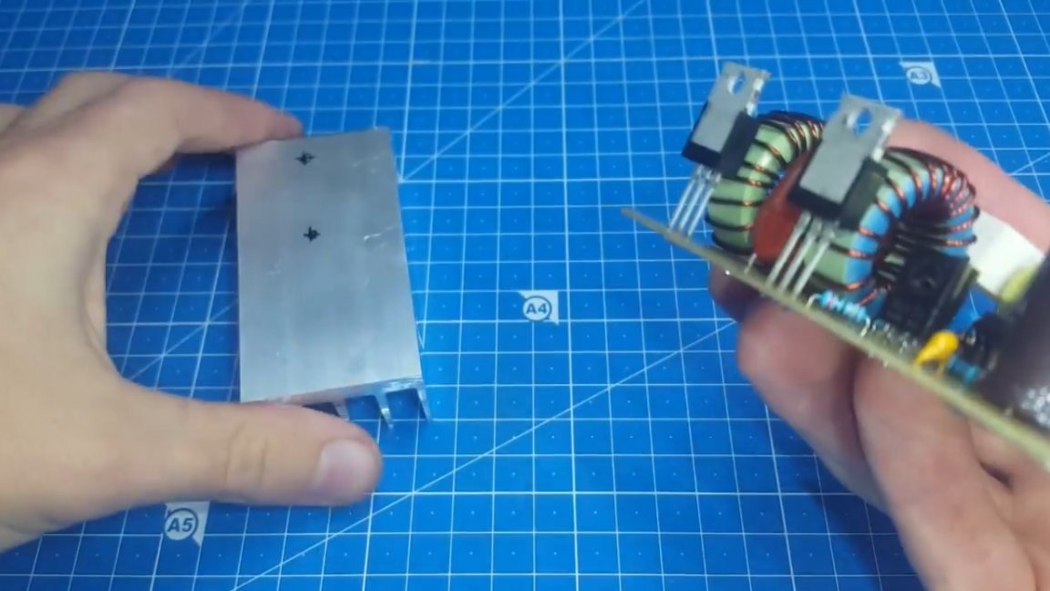
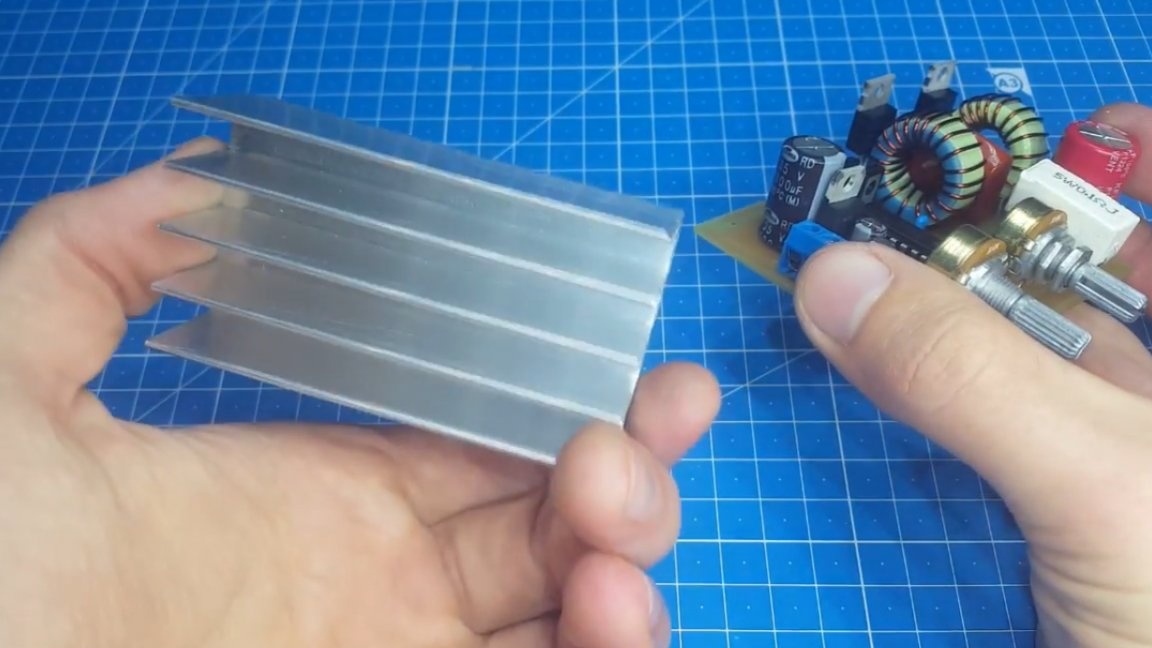
Now you need to install the transistor and diode on the radiator. The author will use such an aluminum profile, it has good dimensions and can cool the circuit normally.
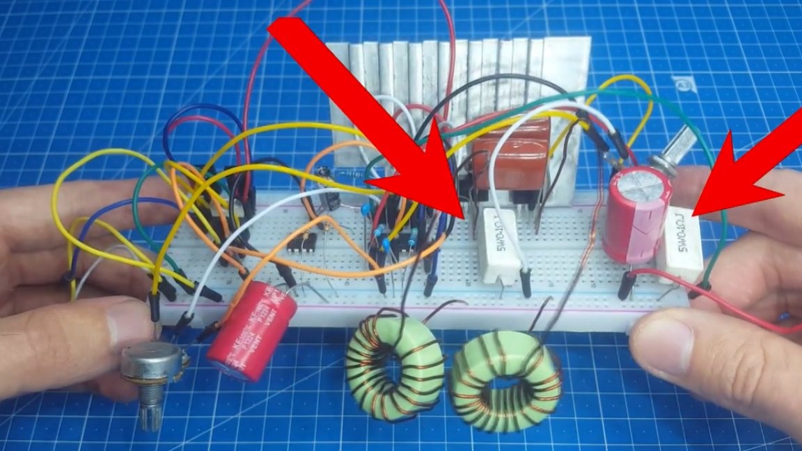
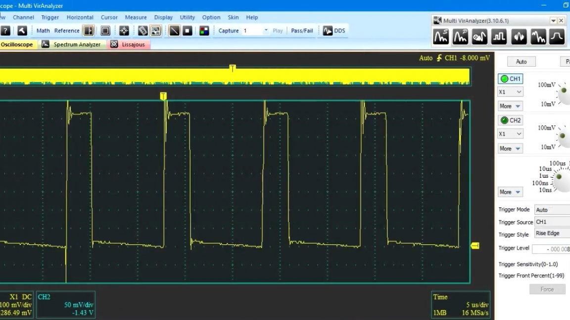
Well, in the end we traditionally have tests. First, feed the circuit with a voltage of 12V. The output is connected to a load in the form of a 100W incandescent lamp, designed for a voltage of 36V. The multimeter monitors the output voltage.
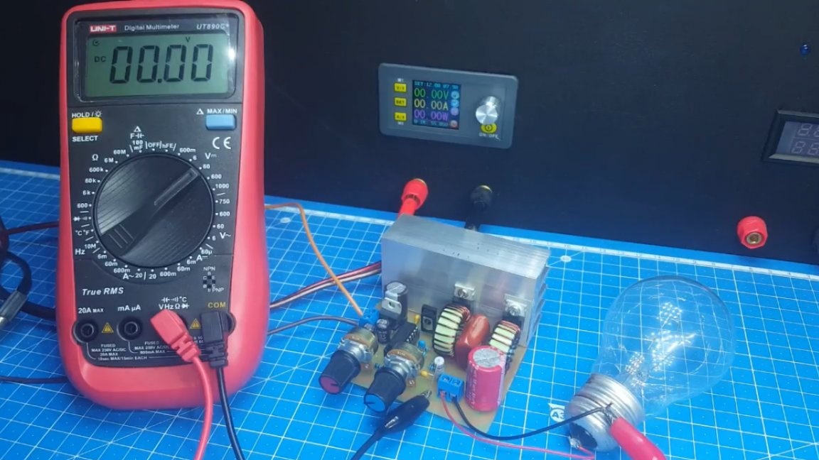
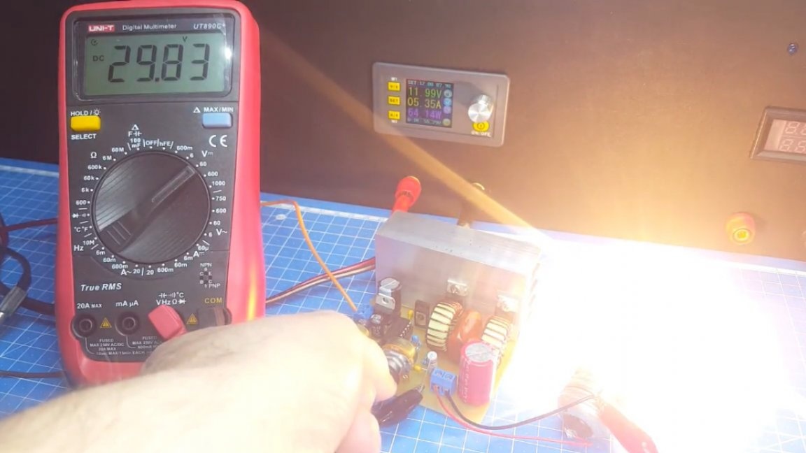
As you can see, we can easily set any voltage starting from 0 and ending with almost 30 volts, which affects a large inductance, which, according to the author, he was too lazy to rewind.
Now let's see the current limit.
As you can see, our circuit does an excellent job. Now make a short circuit.
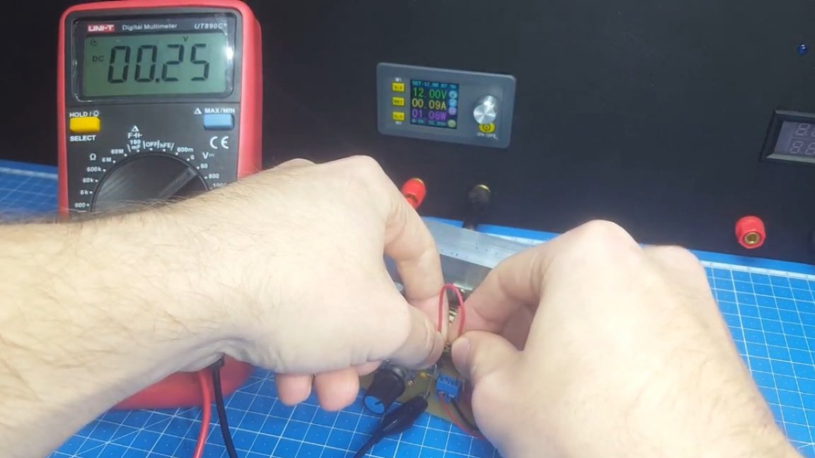
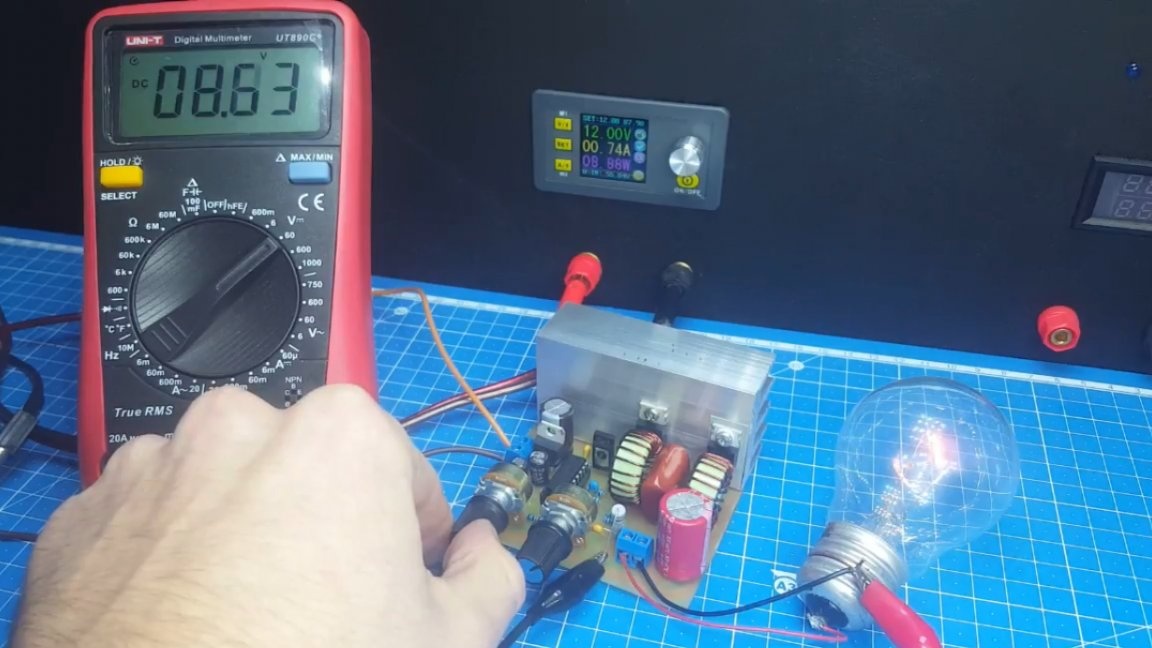
This is generally without problems, there is simply a limitation of the previously set current. Well, the most important test is to set the output to an average value of 15V and begin to change the input voltage.
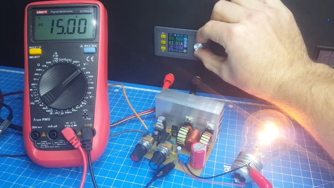
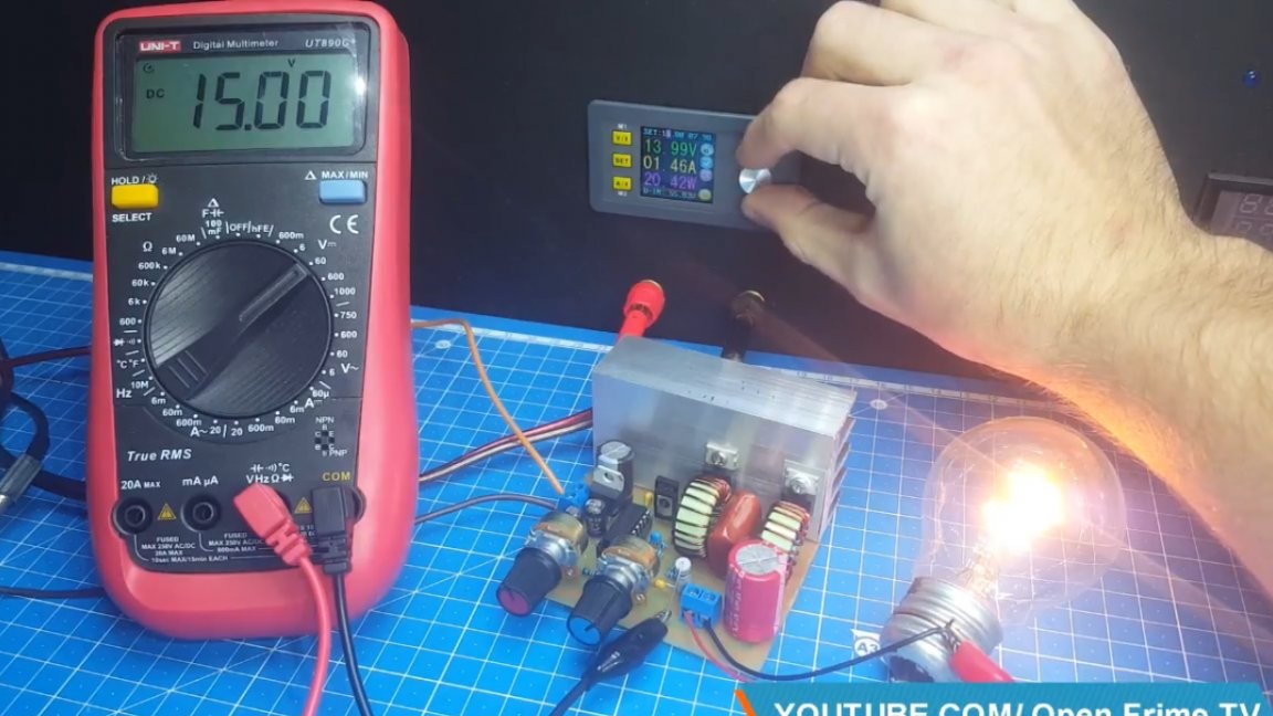
As you can see, at first we reduced it, but now we started to increase it, but the output voltage is kept at a given level.
Well, that’s all, I hope you enjoyed it. Thank you for attention. See you soon!
Video: