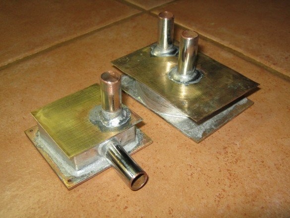
Water cooling, despite its relative complexity and less mobility, has several advantages compared to air blowing. For use in e technology, this is mainly greater thermal efficiency, the absence or radically less noise (fans), the compact size of the heat exchangers for heat removal, the ability to conveniently take out the "returning" heat exchanger outside the device (room, building).
Water cooling can be applied in some cases in stationary devices having parts that intensively generate heat and require cooling. In electronic technology, it can be output stages of transmitters, powerful amplifiers (SP) working in class A, power electronics. A common task is the use of water cooling for the system unit of a personal computer. The latter allows to greatly reduce the noise from the instrument fans, the penetration of dust into the instrument housing, and increase the cooling efficiency.
On sale there are both ready-made sets of designers that allow replacing regular fans of the system unit with cans, hoses, pumps, and the components of these systems separately. Here, the technology of simple and convenient manufacturing of perhaps the most expensive and complex element - a heat exchanger - for heat removal is given. Technology allows for home conditions, without access to machine tools, make an efficient miniature flat heat exchanger. The preparation for soldering and the soldering itself are very simple. Fine fitting of small parts is not required. The configuration of the heat exchanger can be easily adapted to the current task. The requirements for materials are also facilitated - no massive copper alloy ingots are required, just a plate several millimeters thick is enough.
What was required to work.
Instruments.
A set of bench tools, metal scissors, a hacksaw. A jewelry jigsaw with accessories came in handy, but you can do it. Marking tool, small vise. A small gas burner was used for soldering.
Materials
Billets of iron - sheet copper, brass. Tubes of appropriate diameter. Sandpaper, solder, flux for brazing.
Here is shown the manufacture of a set of heat exchangers for the system unit of a personal computer (processor, video card). The dimensions of the heat exchangers were dictated by the fasteners of standard radiators with blowing - trophy mounts were used to the maximum in the new design. The configuration of the nozzles was determined by the convenience of connecting with hoses. Based on the diameter of the connecting pipes at the circulation pump, the diameter of the hoses is 10 mm.
As the basis of the heat exchanger - the soles adjacent to the chip, a 2.5mm thick brass plate was used. After marking, two rectangular billets were cut out of it, using a hacksaw. The ends of the workpieces are aligned with a file, the sharp edges are dull. By several numbers of small skins, the workpiece planes are processed. The side with a minimum of scratches is assigned externally - to the CHIP; it is better to mark it with an alcohol felt-tip pen.
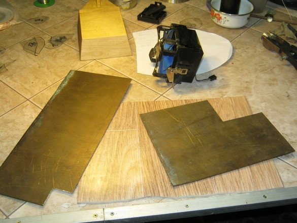
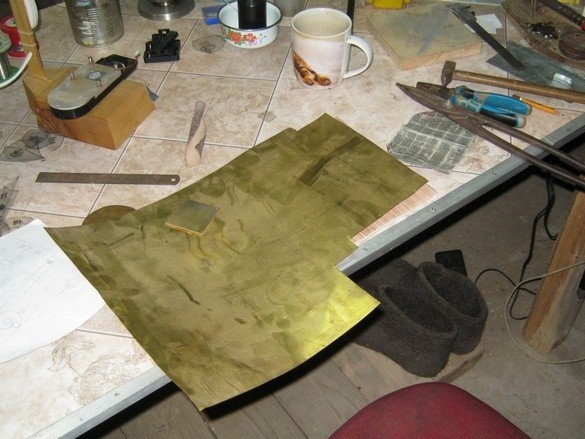
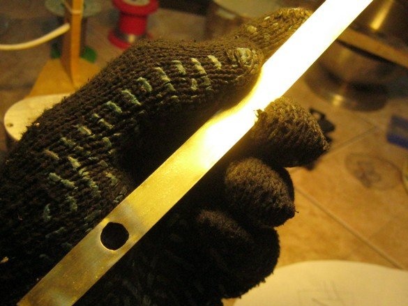
All other parts of the heat exchangers are quite acceptable to perform from a metal much thinner - almost foil. With rigid volumetric mounting by soldering, the design is very strong and reliable. Here, 0.2 mm thick brass sheet is applied. Based on the diameter of the connecting hoses and pipes, the height of the heat exchanger adopted 10 mm In the processor heat exchanger, the height of 11-12mm was due to the mounting used. In the video card CHIP heat exchanger, the inlet pipe was conveniently made in a flat end. The hole in the tape was marked with a compass-ballerina and sawn with a jigsaw file No. 6. The remaining holes for the nozzles in the flat caps are made the same way.
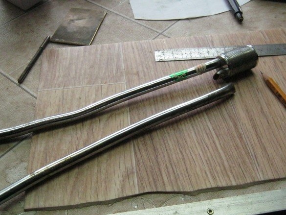
The pipes themselves are made of pieces of a copper chrome tube from old plumbing.
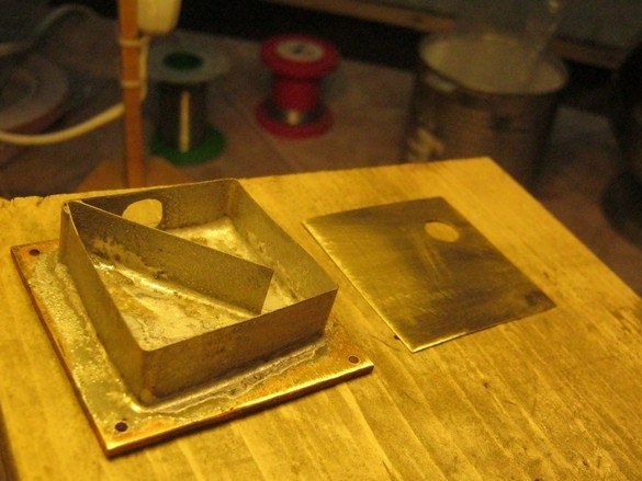
After a thorough stripping (for soldering), the brass strip for the low side walls is folded with a sort of snail on the tube-blank of the pipe. Then a snail of the heat exchanger is formed from it, so that at the beginning and end of it there is enough space for the pipes and the walls do not close too tight and do not protrude beyond the edges of the sole. By the number of revolutions, it is possible to some extent to regulate the amount of heat transferred to the coolant (water). In general, we operate in an intuitive way - the larger the area requiring cooling and the more it is heated, the more turns are required.
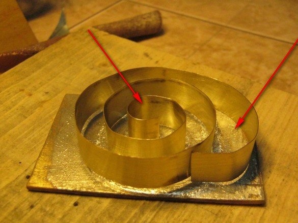
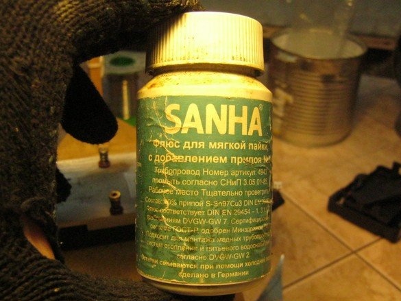
When soldering, a “plumbing” flux was used to solder a copper pipe with a burner. It is designed for lead-free tin-copper solder, but it works perfectly with ordinary tin-lead solder, which is very handy - the latter is half cheaper. You can probably use liquid inorganic fluxes, the same “soldering acid” (zinc chloride). Rosin and fluxes based on it should not be used for soldering with an open flame - they are easily ignited, even if heated from the back, after burning they leave soot making soldering difficult.
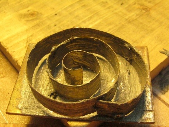
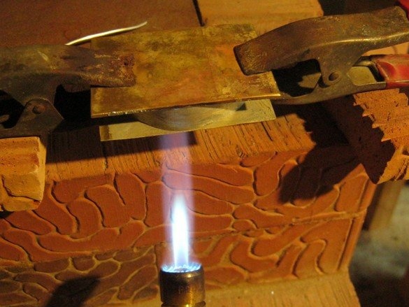
After applying the flux, the rolled tape should be pressed firmly to the base. To do this, you need a technological plate and a pair of metal clothespins or a weight. Inside the contour, evenly place small pieces of solder. Here we used POS-60 in the form of a 2.5 mm thick wire. He cut it with cutters into particles of 5 ... 7mm.
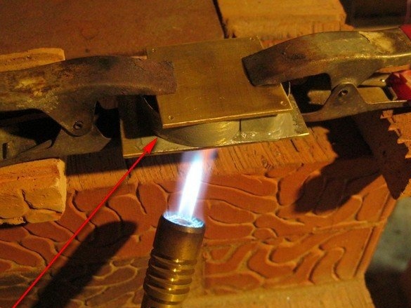
We heat until the solder melts and completely tightens the contour of our snail fence. Between the sole and the wall. It should be remembered that solder flows into a place with a higher temperature. If the solder is not pulled into a certain area, you can help it by touching or stroking it with a twig of the “external” solder. You should not heat the workpiece for a very long time - the flux is burned and stops working.In this case, it is necessary to cool the workpiece, disassemble, clean and repeat everything again. But with careful cleaning of surfaces and plenty of flux, everything works very well.
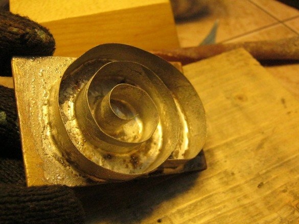
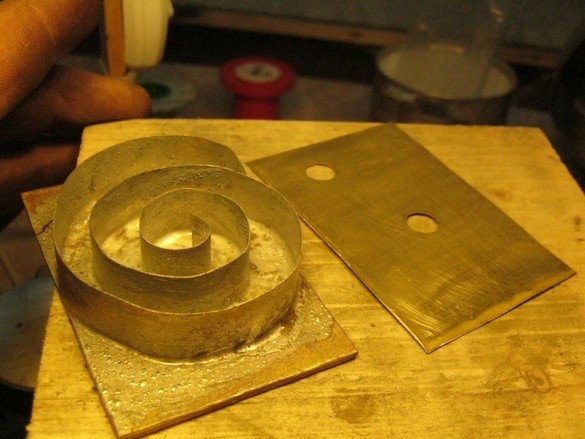
I cut a lid from the same thick brass foil, marked out and cut out two holes for the nozzles with a jewelry jigsaw. The shape of the lid is rectangular in the shape of the sole. It turns out more aesthetically and more conveniently cut. If the material is not particularly expensive (thick foil), I recommend this form. By the way, my 0.2 mm foil is quite successfully cut with large rough tailor's scissors, although special ones for metal are certainly more convenient.
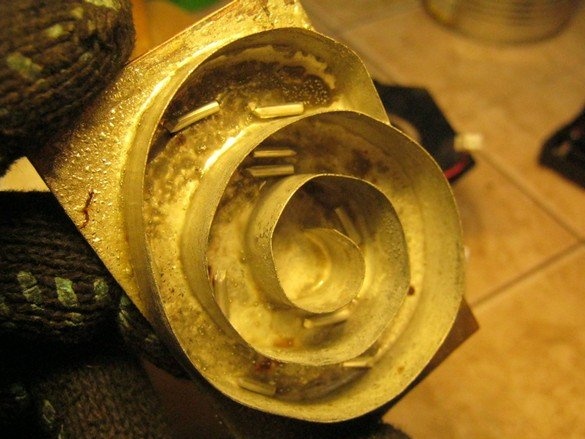
After manufacturing the blank of the top cover, carefully clean it and apply flux. On the lid and the upper edges of the cochlea. Inside we again lay the pieces of solder, put everything together and turn the lid down. Just in case, you can shake the blank of the heat exchanger assembly so that the pieces of solder, probably sticking to the walls or ceiling (flux - thick paste) fall to the bottom (cover). Again we heat the burner, if necessary, we wield a solder rod outside. Let cool.
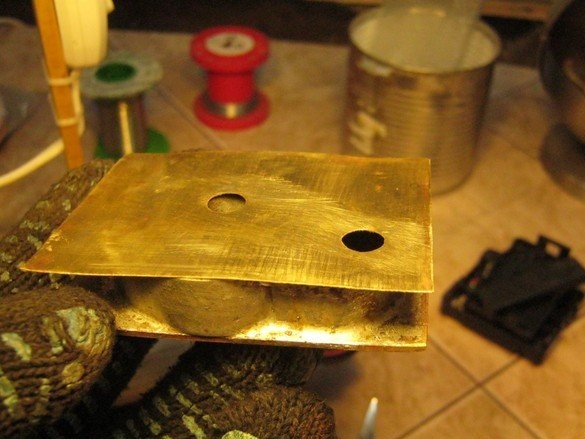
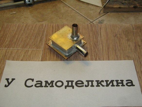
The heat exchanger cover was carefully cleaned with a fine sandpaper and prepared a pair of hose fittings. Since my workpieces are from chrome plumbing, it is better to strip the edges for soldering to copper. Solder to the coating no worse, but the strength of such a connection will be less - old coatings, in addition, tend to peel off.
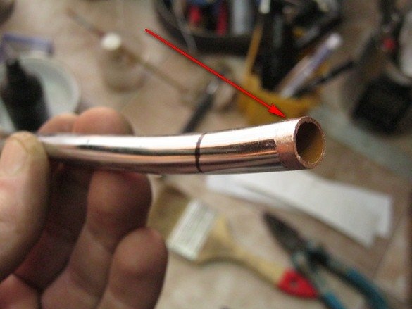
I sawed it off with a hacksaw for metal, cleaned it up, put a flux on it, and wrapped a solder ring on each fitting.
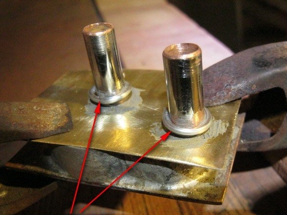
When carefully heated with a small flame of the burner, in order not to dissolve the rest, the solder melts, slides down into a neat roller. It is better to heat the fitting itself, and after melting the solder, a bit and a cover around it.
After the heat exchanger has completely cooled down, everything that is available should be thoroughly washed from the flux with warm water and a hard brush. The flux inside will have to be washed out - after assembling the closed cooling system, you should change the water 3-4 times, well, say, every 2 days of operation. This is exactly what the manufacturer of flux advises in the case of installing copper water supply.
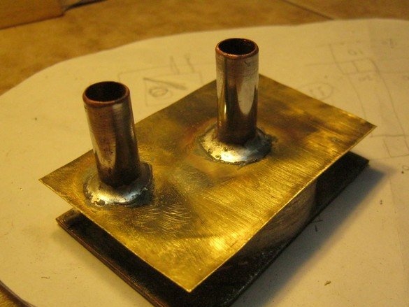
The heat exchanger for the chip of the video card is smaller, simplified configuration of the internal cochlea and the location of the fittings. Another method of fastening is with four standard spring-loaded screws. In general, the technology is completely similar.
conclusions
Practice has shown reliability, availability and sufficient design efficiency. Together with the simplicity of manufacture, the technology seems to be quite reasonable and is recommended for repetition.
A few words should be said about the selection of materials. Since good thermal conductivity (soles) is required, it is better to use copper or copper alloys, among other things, this will simplify the choice of fluxes for soldering. It should also, of course, be excluded from the design of metals forming a galvanic pair with copper.
Babay Mazay, January, 2019

