
Sometimes in amateur radio practice there is a period when you want to collect something to calm the nerves, something spiritual, warm and lamp. Nostalgia is an uncontrollable thing, so the author of today's homemade AKA KASYAN (YouTube channel “AKA KASYAN”) spent 2 days building this design.
In his videos, the author never hid the fact that he greatly appreciated Soviet electrical appliances, even the most unsuccessful ones. In early childhood, the author had a couple of hours to work with the IPS-1 power source (the most common adjustable voltage regulator).
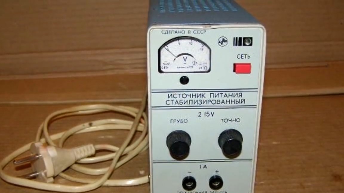
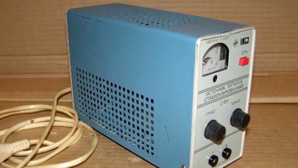
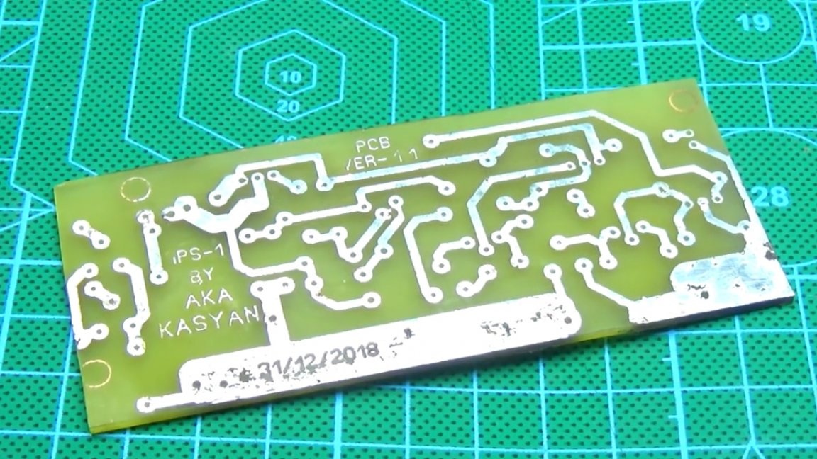
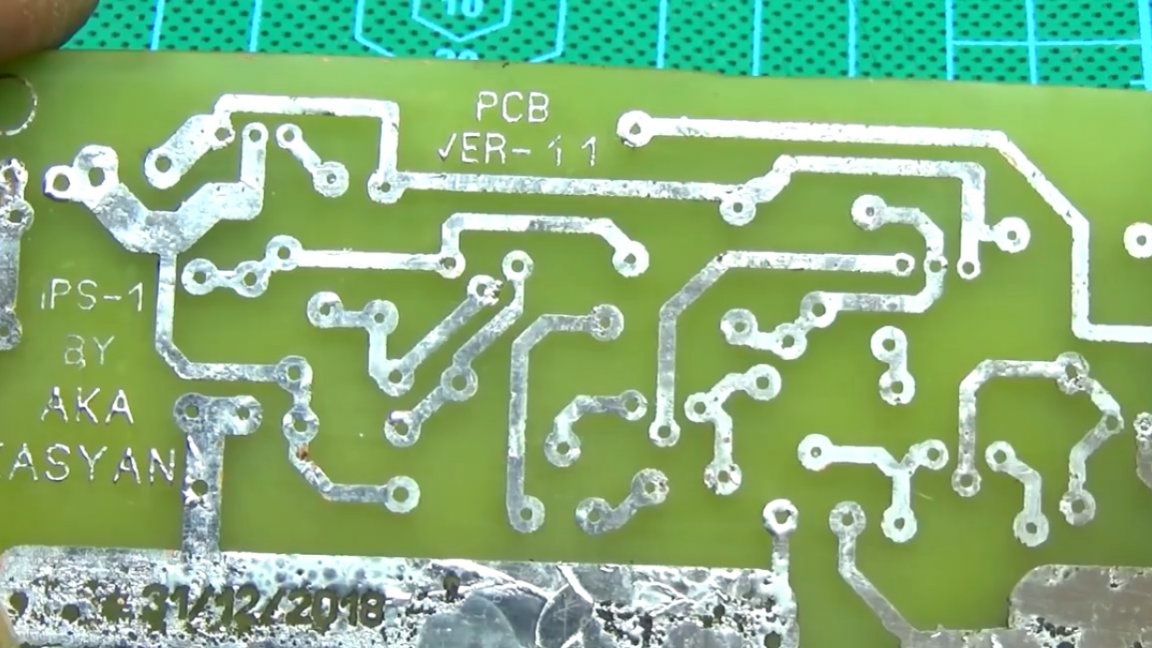
It would seem that nothing special, but this block he remembered for a long time, unusual, compact and even by today's standards is quite stylish. And now, after almost 20 years, AKA KASYAN decided to assemble the circuit of this power source, moreover, to assemble completely on authentic Soviet radio components, the search of which had to be spent the whole day, despite the fact that there are not so many details in the circuit.
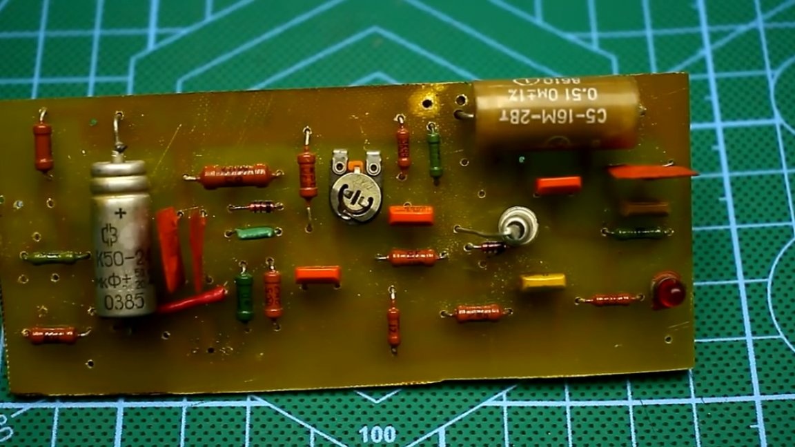
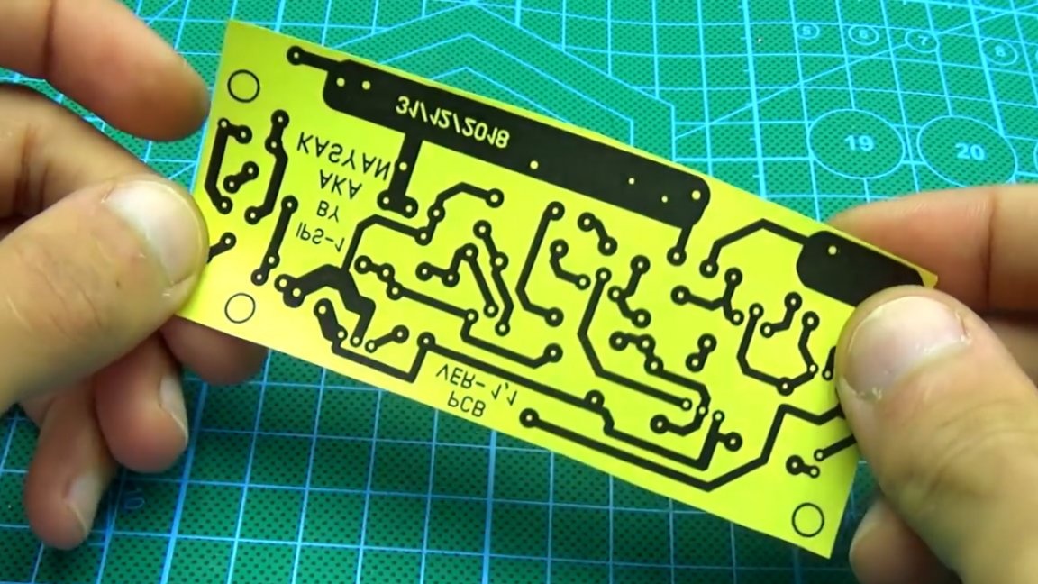
The author developed this scarf on the last day of 2018.
The print quality did not work out very well, since the printer cartridge is already breathing through one place, even the use of thermal paper did not save.
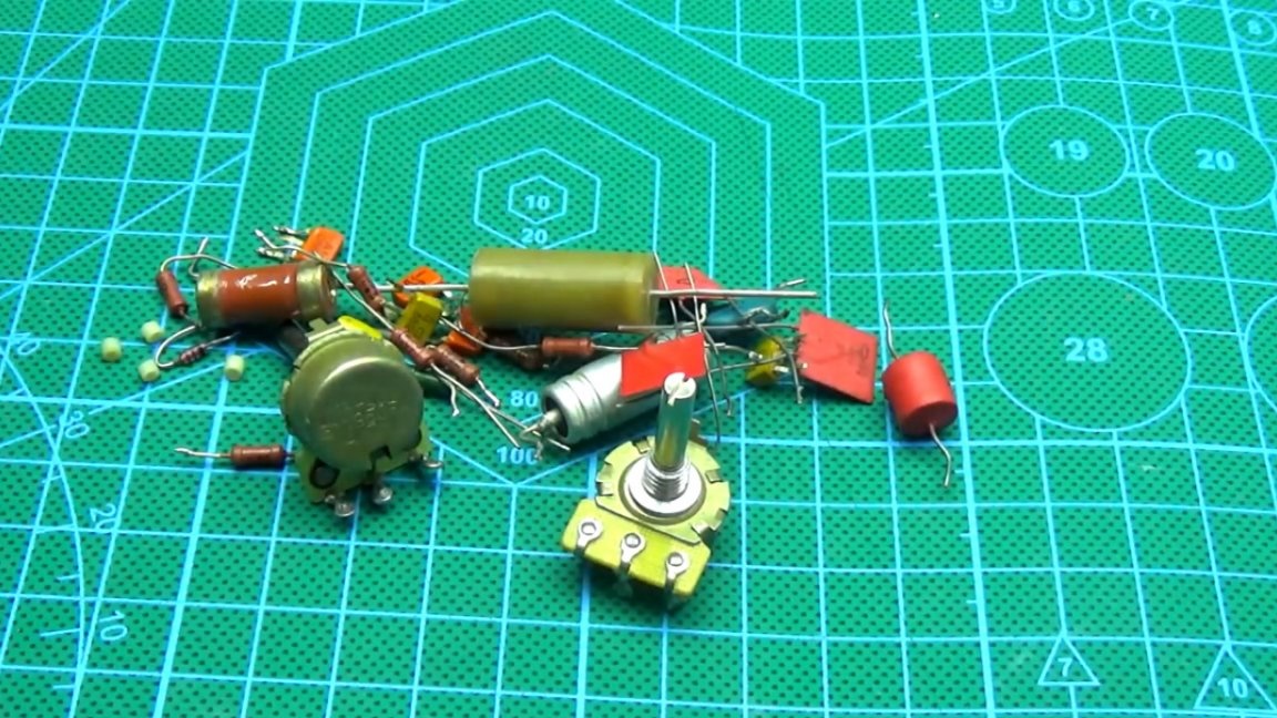
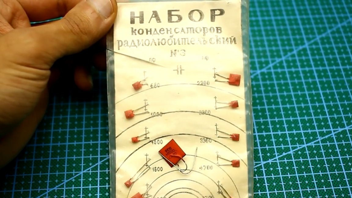
Then began the tedious process of finding the right parts in the attic. Saying an attic, an entire room is meant to be packed full of various rubbish.
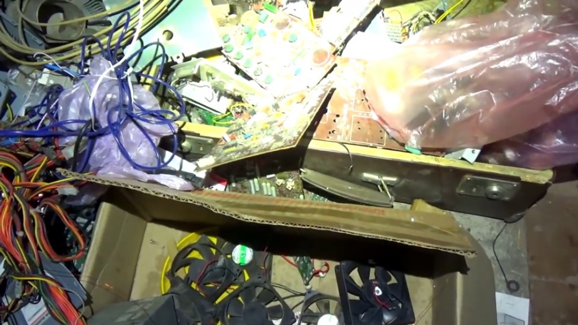
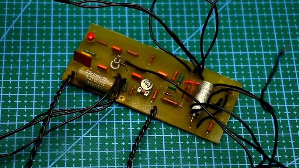
The assembly of the power supply took about half an hour from the force.
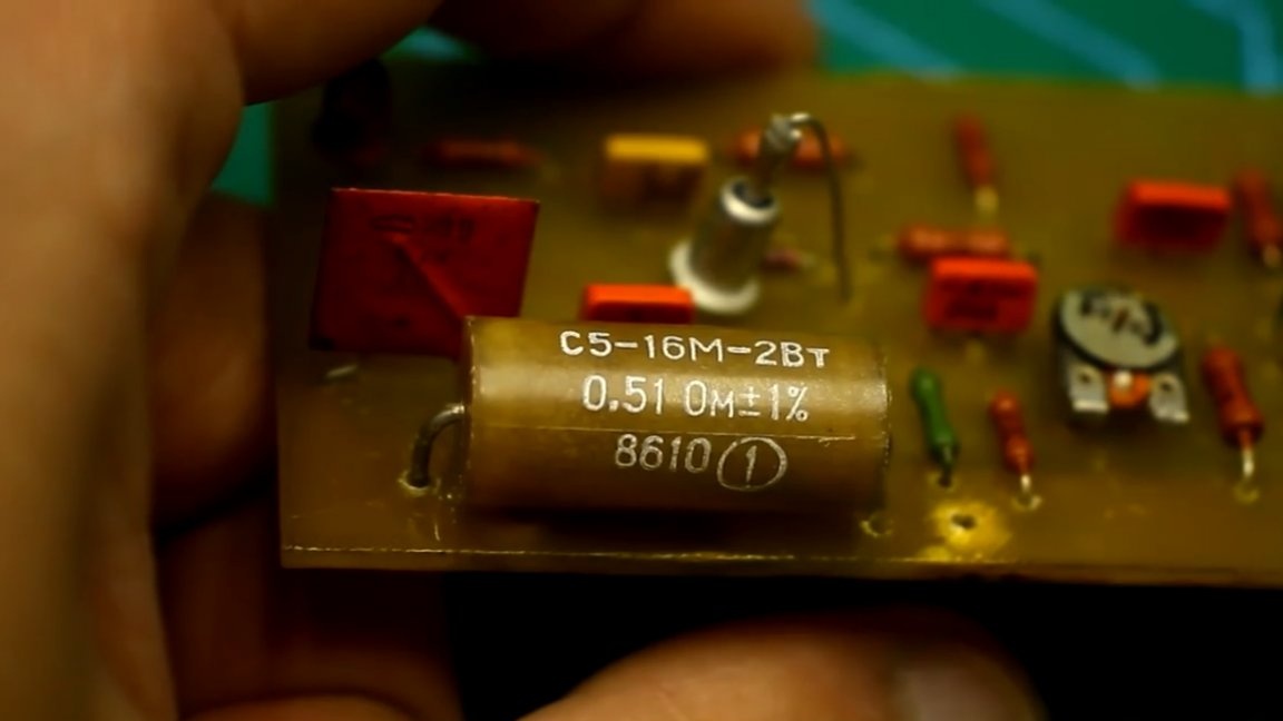
Almost all components are Soviet, with the exception of one of the Tesla interlinear components, yes, and this is not the Tesla you thought of. It's about the good old company Tesla in Czechoslovakia, which produced almost everything.

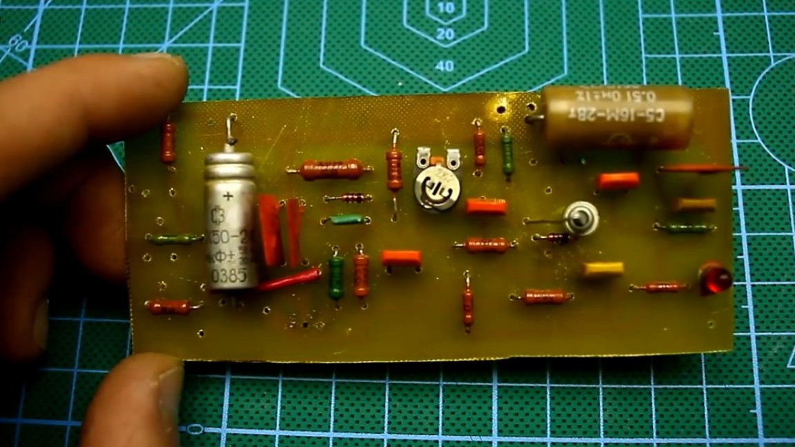
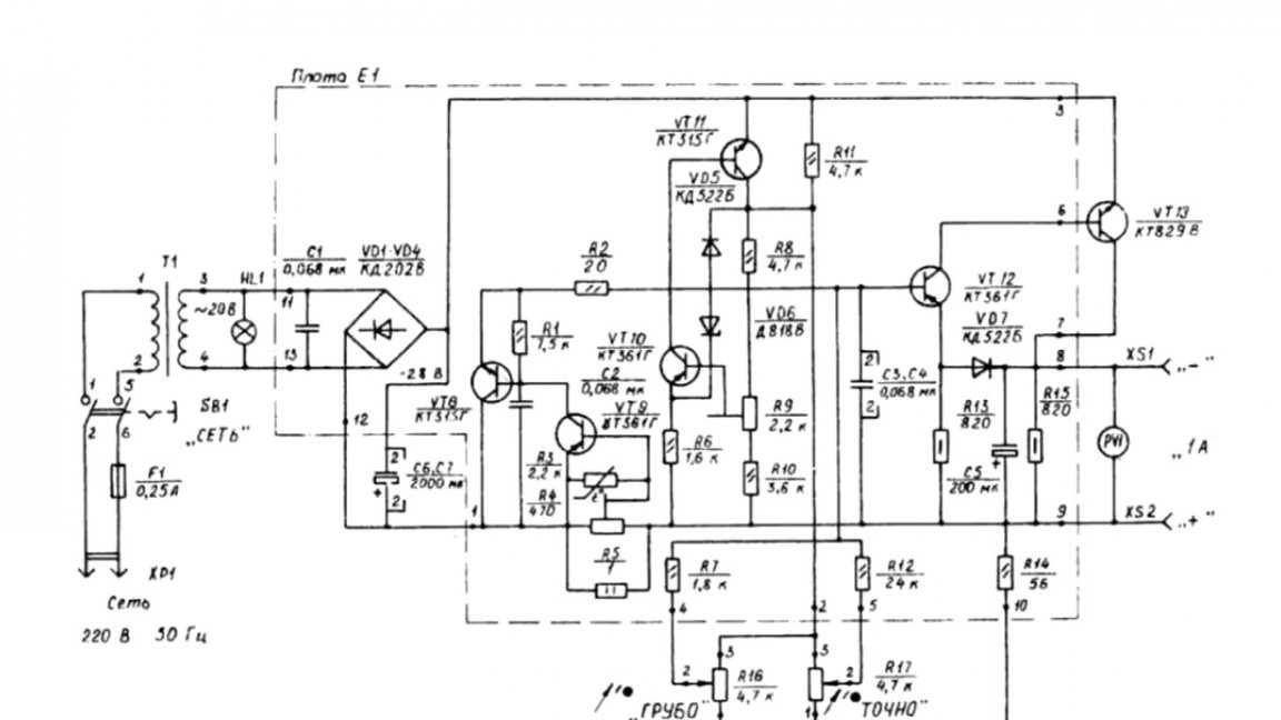
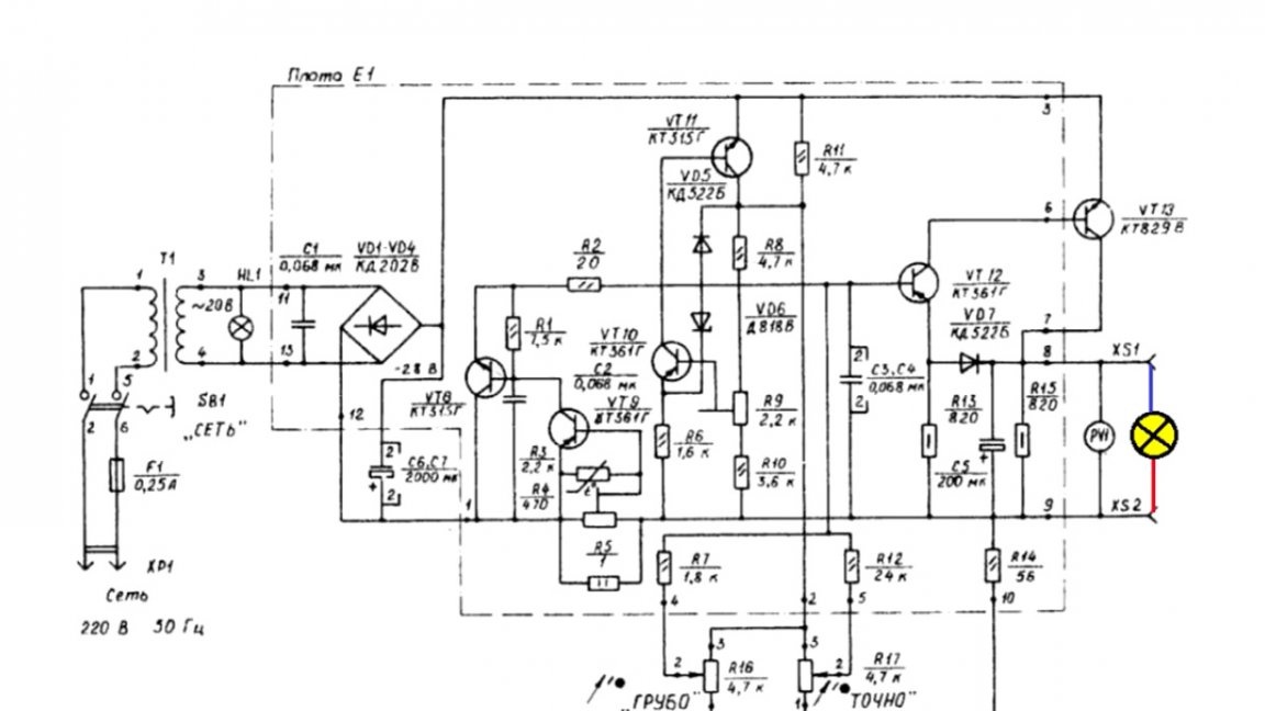
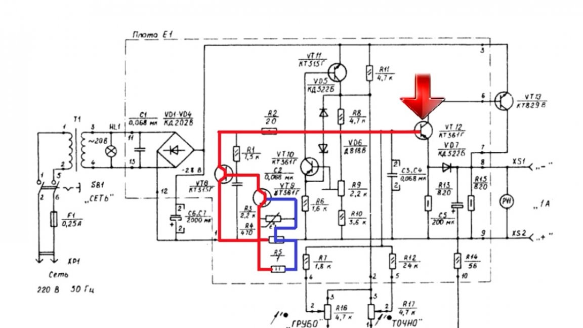
Let's get back to our power source. Before you now circuit:
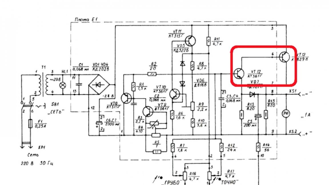
It is built on 6 transistors, 5 of which are low-power.
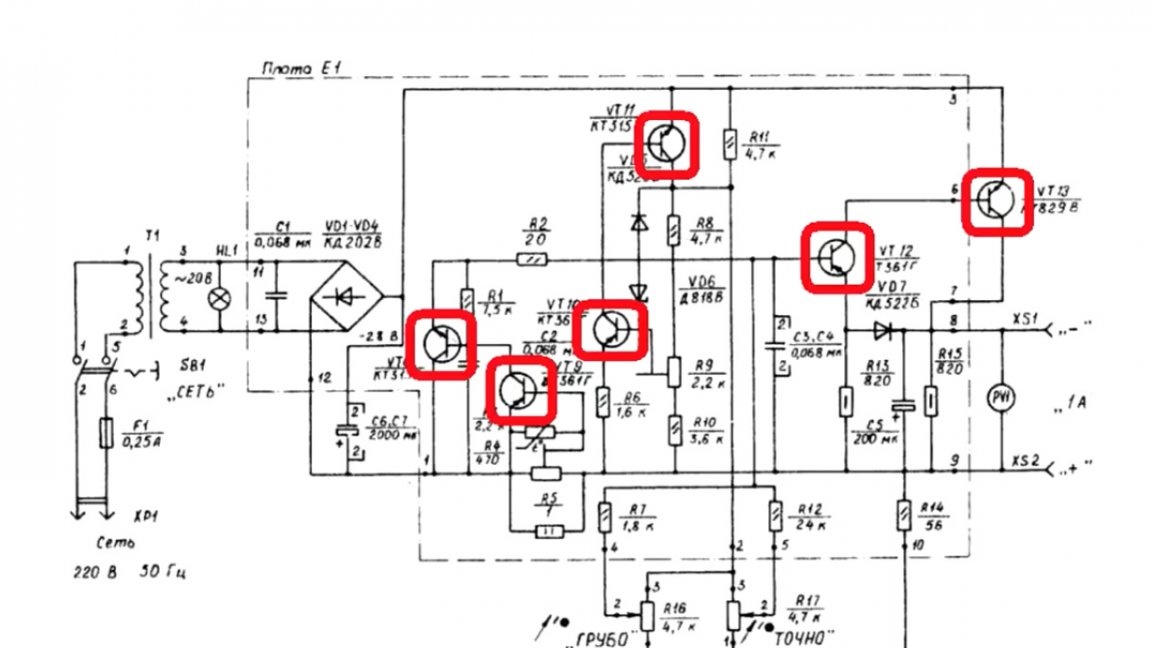
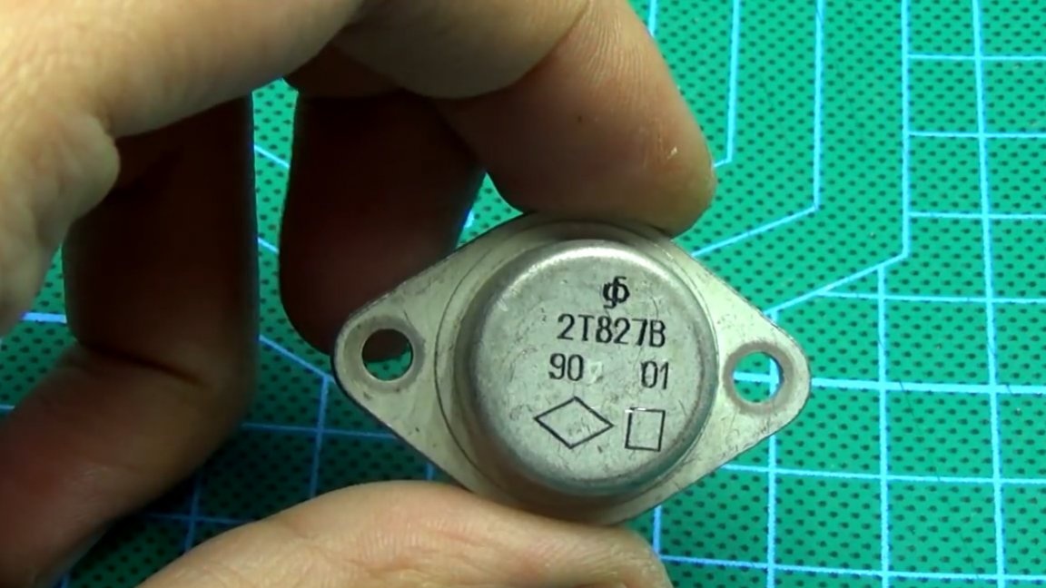
Power transistor composite.
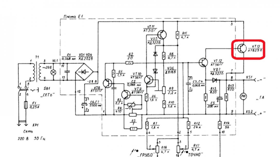
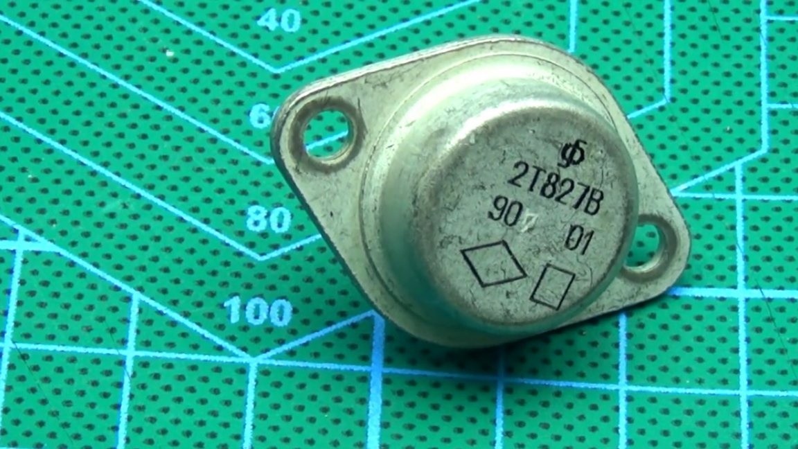
According to the scheme, KT829 was installed, but the author put a much more powerful one - the legendary KT827, also composite reverse conductivity.
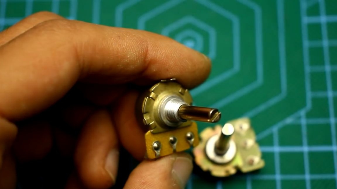
According to the scheme, there are minor deviations that do not affect the operation: 4 variable resistors, 2 of them are trimmers, the rest are designed for rough and smooth adjustment of the output voltage.
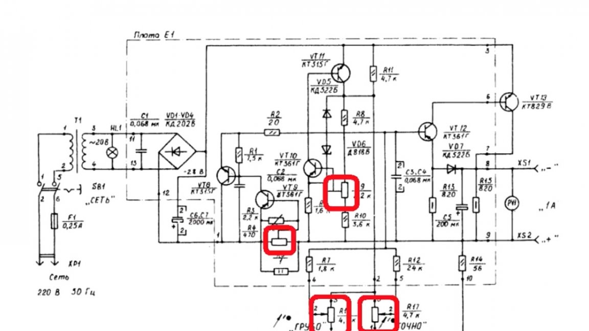
The first resistor is responsible for limiting the current, a kind of current protection. If desired, this resistor can be brought out, in which case the unit will be able to limit the current.
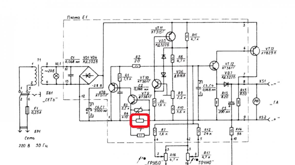
The initial circuit is designed for an output voltage from 0V to 15V and a current of 1 to 1.2A, and believe me, this is enough for most tasks, but the power of the circuit can be increased by replacing the power transistor and reducing the resistance of the current sensor.
The second tuning resistor will allow you to set the upper limit of the output voltage. It must be borne in mind that the output voltage of the circuit is always less than the input, in this case somewhere by 2-3 volts.
The reference voltage source is assembled on a pair of KT315 - KT361 and a zener diode.
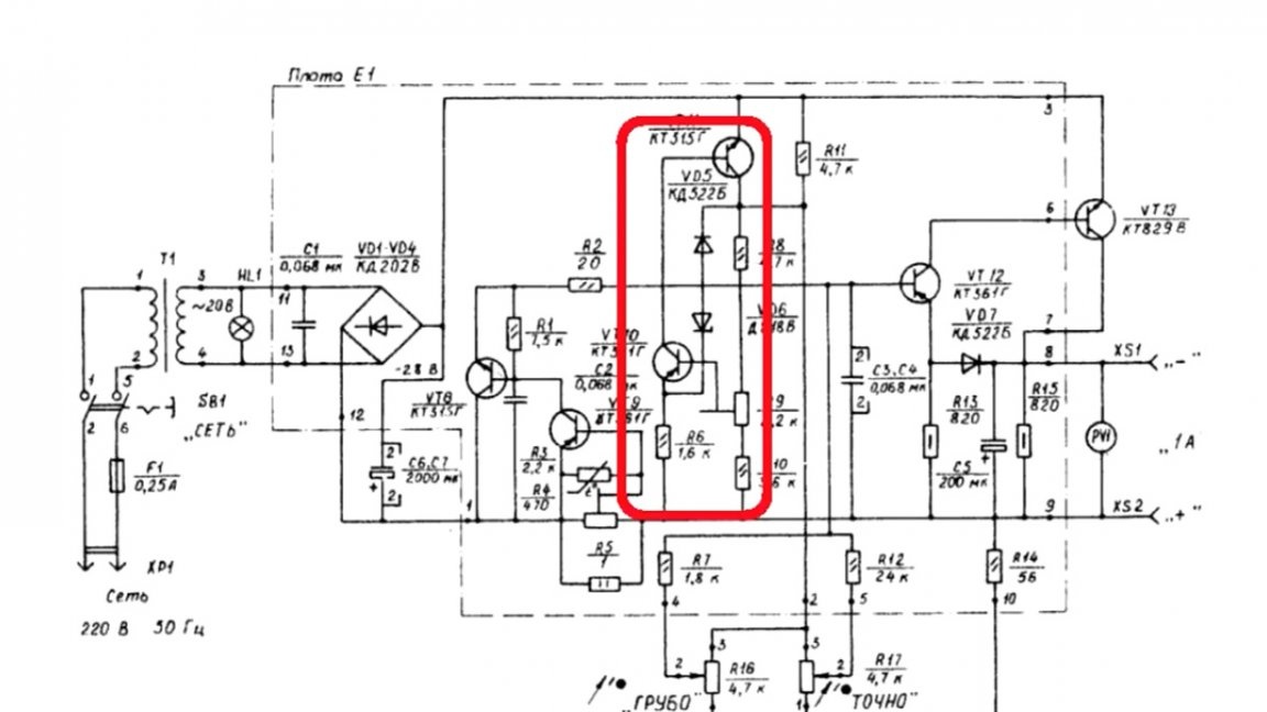
Further, the output voltage from the reference source through the divider is supplied to the amplifier stage.
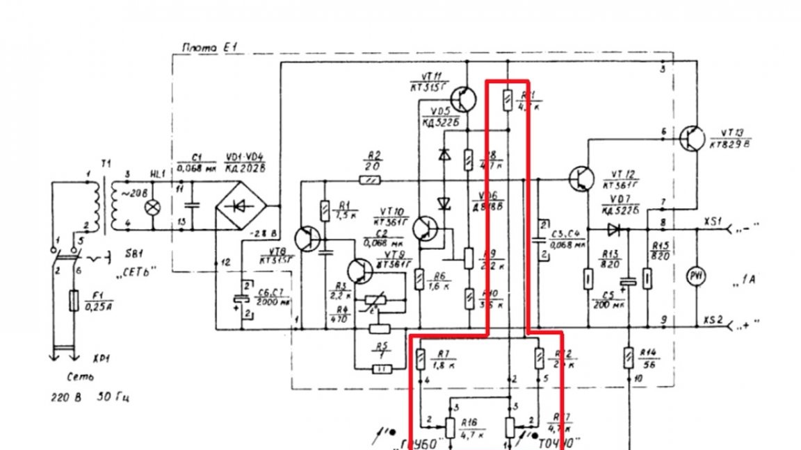
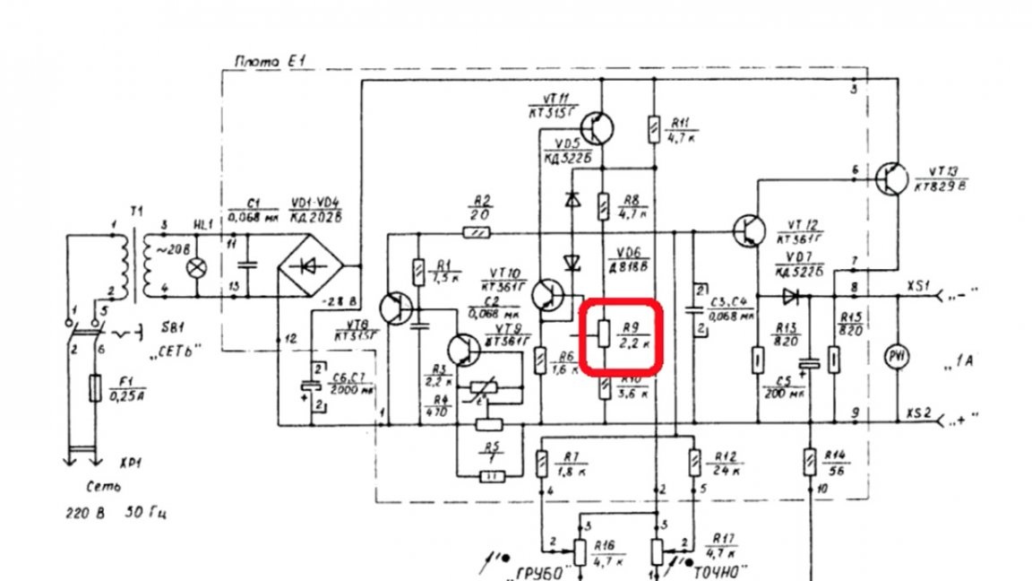
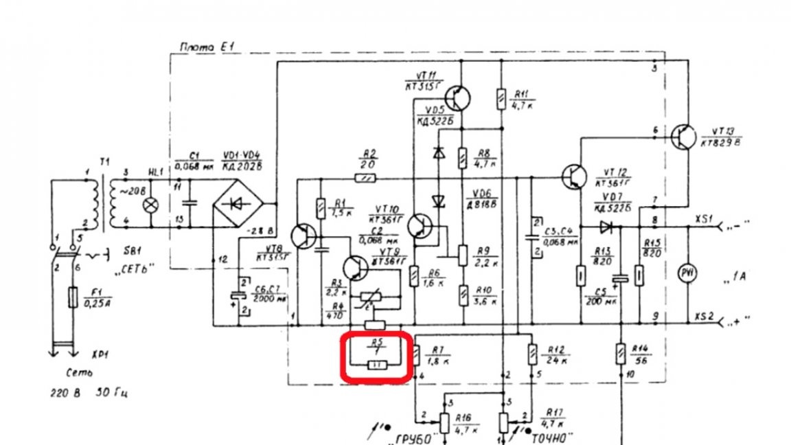
The current limiting circuit is as old as this world - the current sensor, represented by a low-resistance resistor.
If the output load consumes current above a predetermined limit, the lower transistor will trip, since the voltage drop across the current sensor is enough to unlock it.
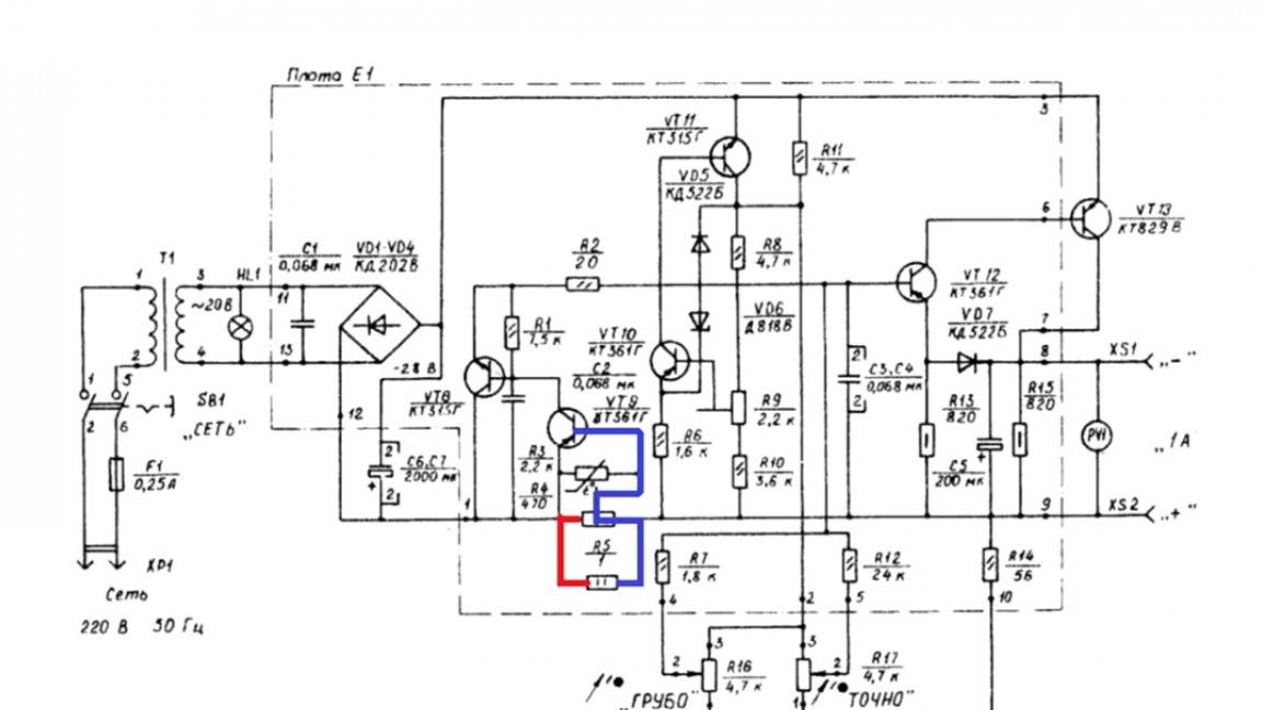
Following it, a second transistor will open, which will mute the signal based on the control transistor. This one will start to close, and therefore the output transistor will close.
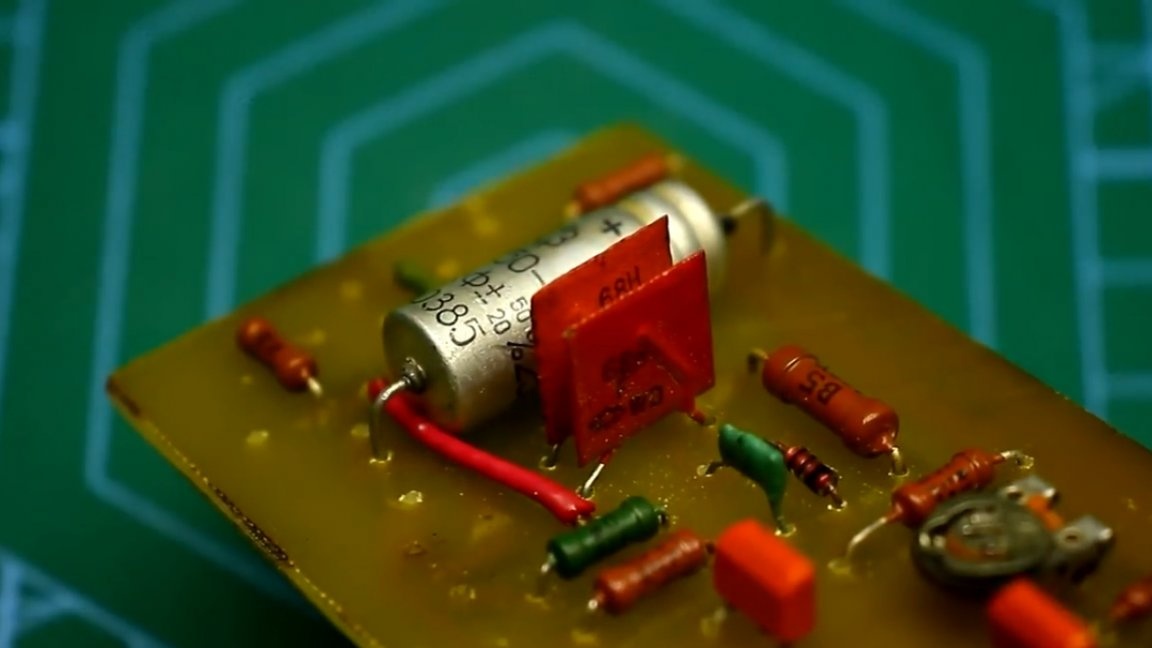
By design as a whole. In general, those who worked with Soviet components know both the advantages and disadvantages, but, frankly, they had more shortcomings, take at least the same KT315. They are of course cool, but fragile, the conclusions can easily come off if a used transistor.
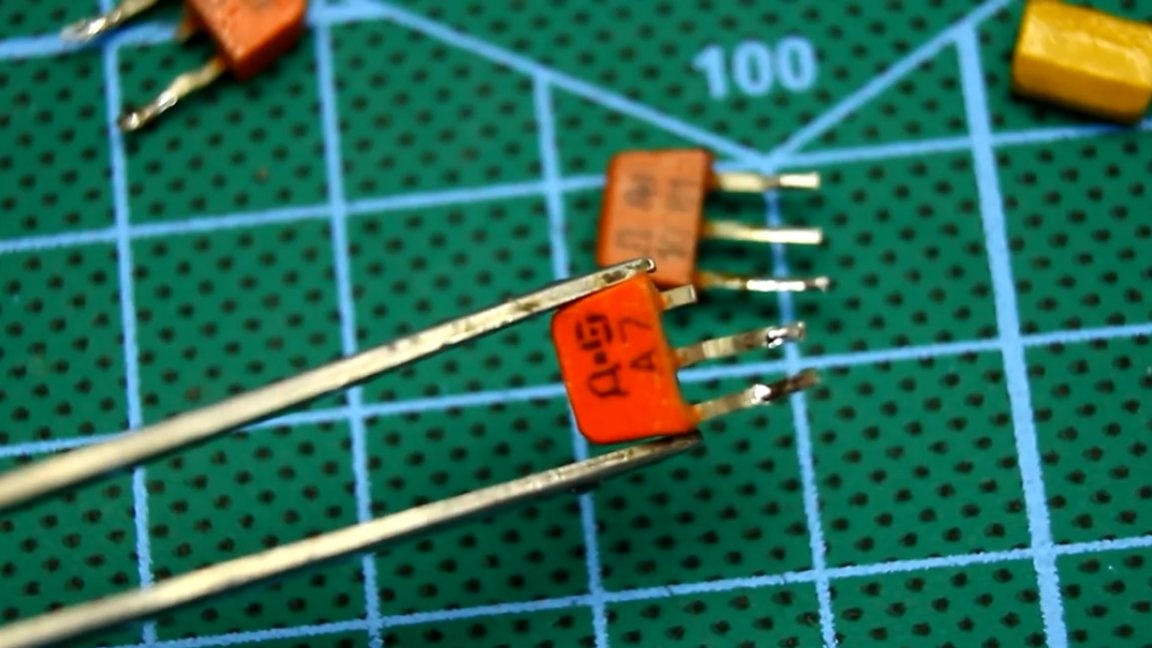
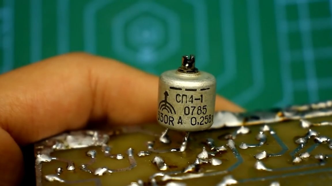
But these beauties (in the common people flags), have a lot of disadvantages.
The main ones are a big leak and the fact that they break even with very gentle handling.
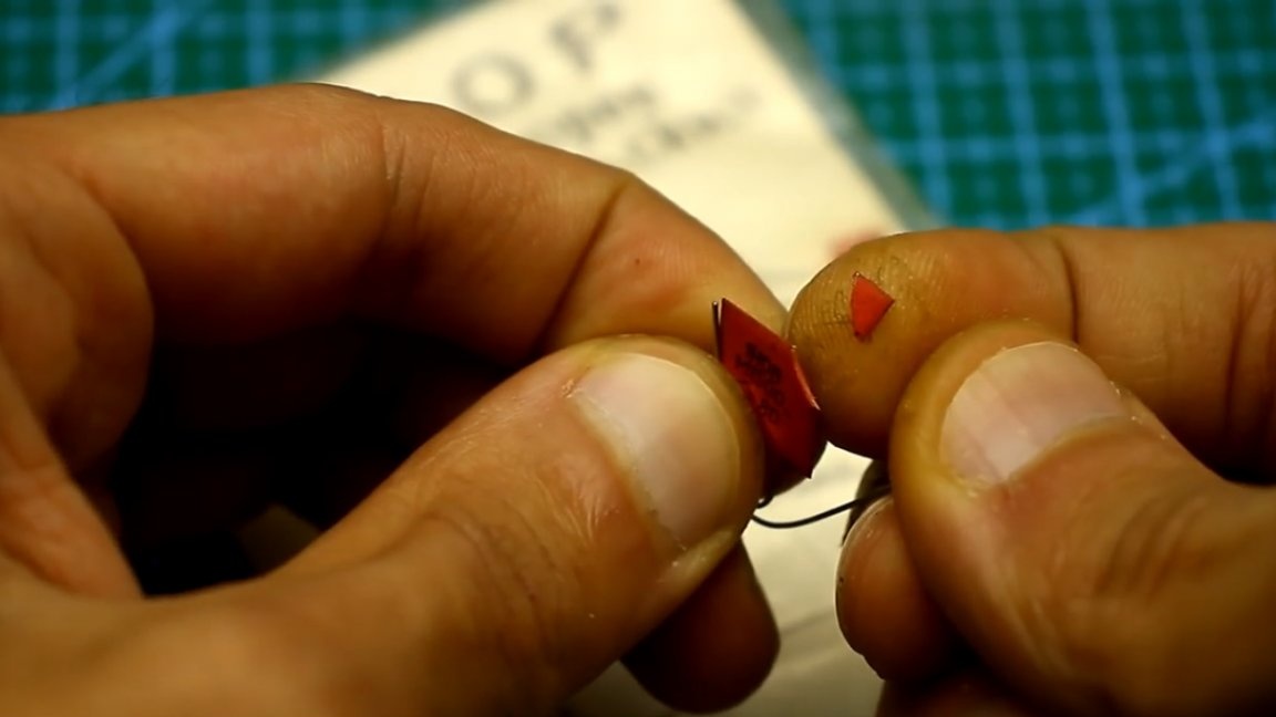
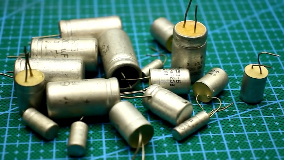
Shovel variable resistors are generally a separate issue, but we will not even talk about them. Well, and electrolytic capacitors, it is better to keep silent about them too. Well, they were good, but there were a lot of bad ones too.
But KT827 is a transistor, which is very popular today. It will easily compete with modern counterparts. The transistor is just a fire, sorry it costs like a lamborghini.
Well, let's finally try out this newly made power supply unit on ancient radio components. It is worth saying in advance that the current shunt that the author installed has less resistance than in the circuit, so the maximum current that a particular unit can give is somewhere around 5-7A. In this case, the transistor needs very serious cooling.
Let's start with the output voltage adjustment range. About 19V of constant current is supplied to the input.
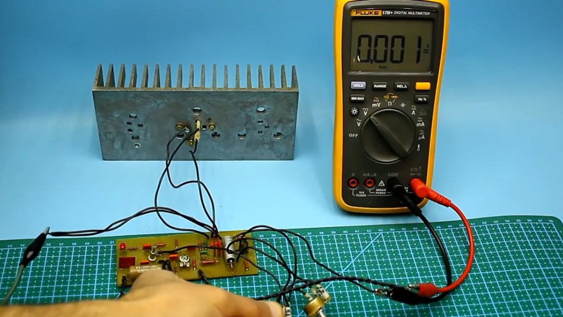
The adjustment, as we see, is very good and starts from zero. The changeover, responsible for the smooth adjustment, is very useful here. A full revolution of the slider of this resistor allows precise adjustment in the range of 1.5-2V.
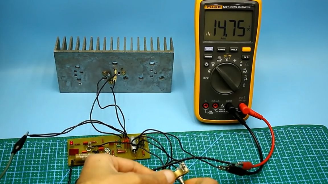
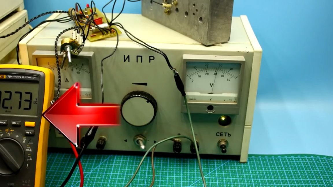
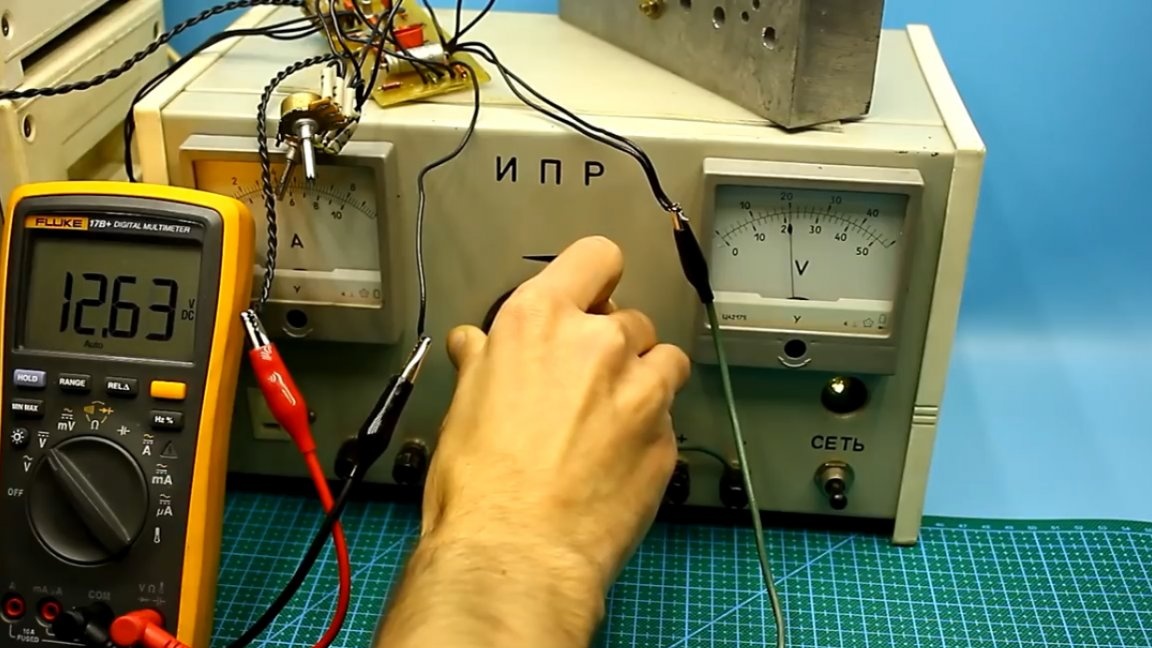
Now let's check the stability of the output voltage. At the moment, a constant voltage of about 30V is supplied to the stabilizer input from a harsh Soviet regulated power source.
The multimeter shows the set output voltage of a homemade stabilizer.
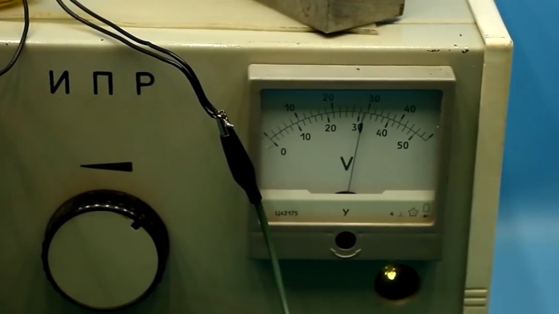
The voltmeter shows a constant voltage that is applied to the input of the stabilizer.
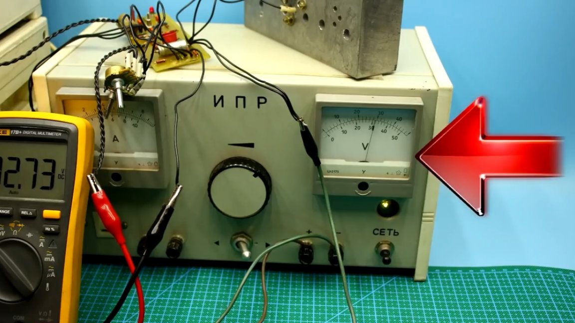
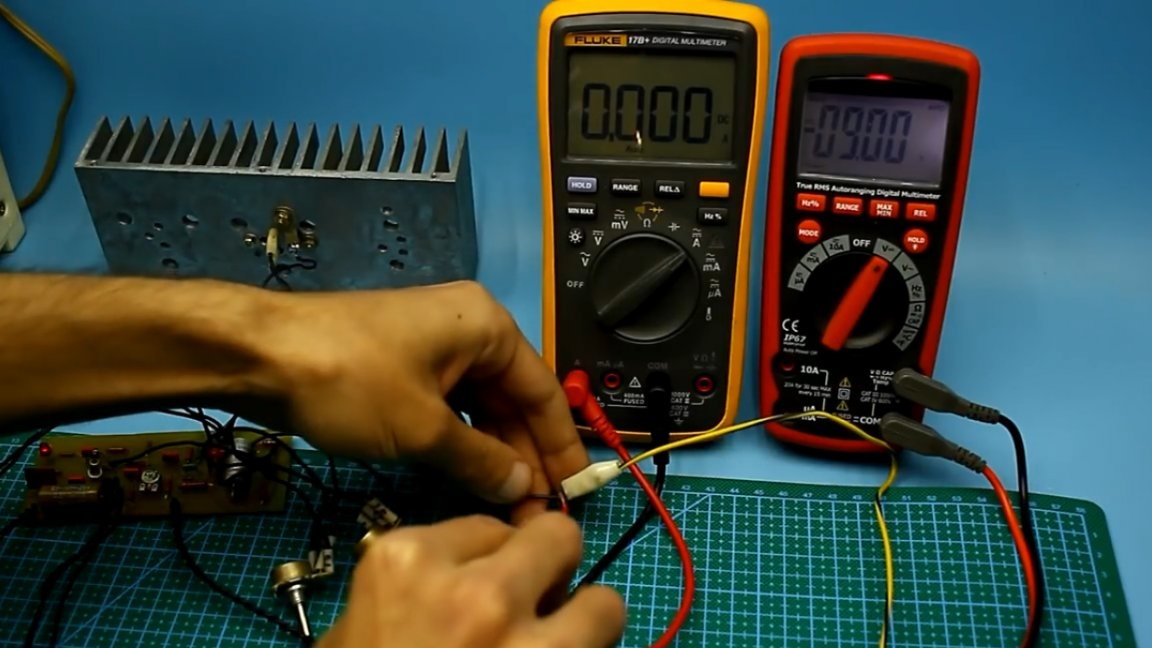
We lower the input voltage from 30 to 20V, simulating a hard voltage drop in the network.
As you can see, the output voltage from our stabilizer dipped somewhere around 100 mV. This is a good indicator, given the simplicity of the circuit and the fact that the reference source is built on the basis of a zener diode. And so, with drops of 5-6V, the output voltage is kept very stable.
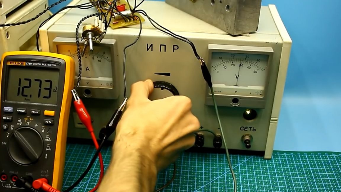
Now let's check the output voltage drop at different currents. Let's start with a value of 2A. In this experiment, a red multimeter shows the voltage at the output of the stabilizer, and yellow - current.
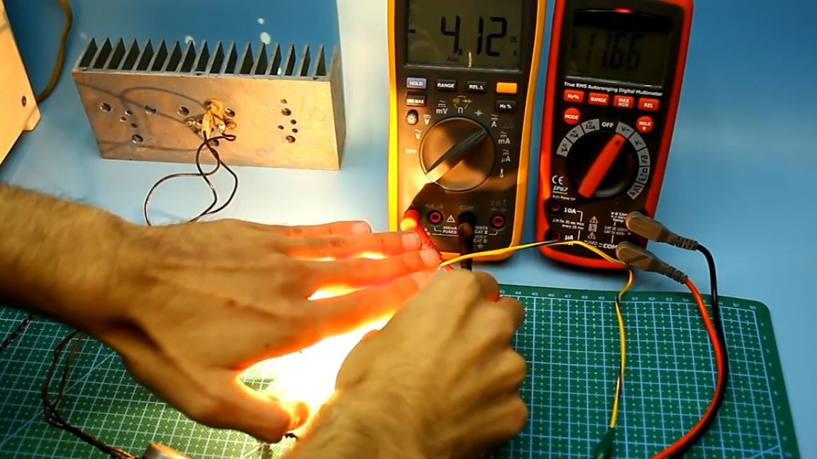
As you can see, the drawdown was only 200 mV. Now the same with a current of 4A.
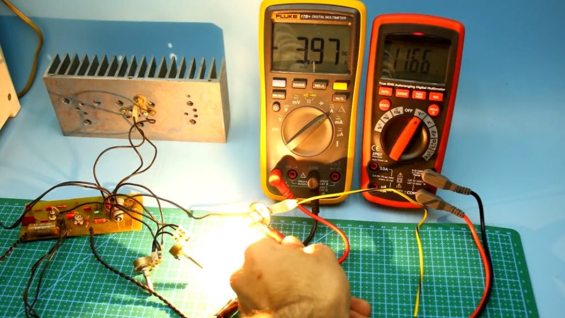
The drawdown in this case is already 350 mV. Is it a lot or a little? Given the fact that there are losses in the wires and the fact that the power supply is simple, at a current of 4A, such a drawdown is quite normal. We can say that this is a very high indicator for power supplies of this class.
Another important point: the rotation of the current limitation controller does not affect the output voltage of the unit in any way if there is no load. The maximum limiting current in this case is up to 7A, but it is extremely undesirable to drive on such currents, the outrageous power is dissipated on the shunt. And so, about 5A can be removed without problems, only take a shunt at 10W with a resistance of 0.5 Ohms.
More details about the operation of this power supply in this video:
Thank you for attention. See you soon!