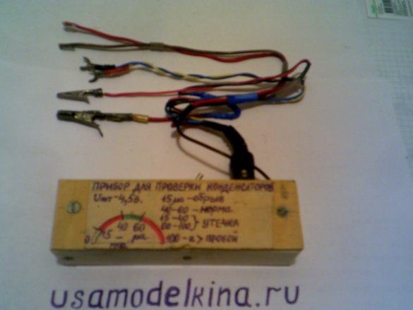
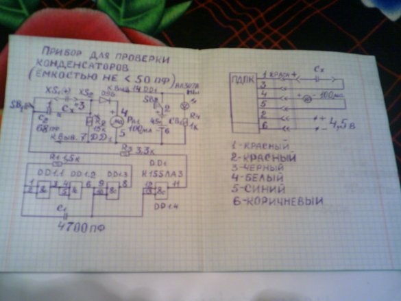
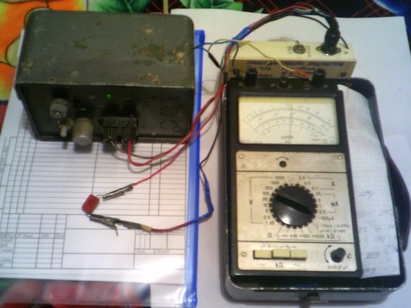
When assembling almost any amateur radio circuit, where there are capacitors, they must be checked for serviceability before assembling the circuit. To do this, I assembled a device for checking capacitors. The scheme was taken from the collection by B. S. Ivanov “To help the radio circle”, Radio and communications. 1990, 3rd edition. Here is a diagram of the device.
For assembly, we need the following parts and tools:
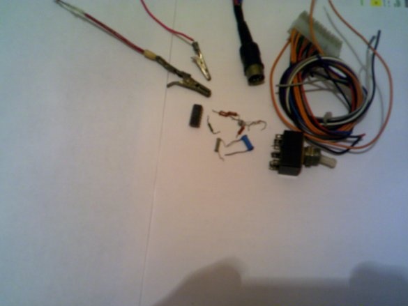
1 - microcircuit K 155 LA3, Resistance 0.25W, 1.5kom, 15kom, 3.3kom, 1kom, Capacitors 4700pF, 68pF, D9B diode, AL 307A LED, two buttons, or a six-pin double toggle switch , mounting wires, solder, two 5-pin tape connectors “male” and “female”. 2- soldering iron, tweezers, nippers, pliers, drill, drills, screws and nuts М3 М4, two small corners, Small-sized housing, Foiled, fiberglass for PCB. We assemble as follows. Step 1 - we make a printed circuit board. Every schoolchild knows how to make it.
After that, we solder the parts on the board, according to the scheme.
Step 2
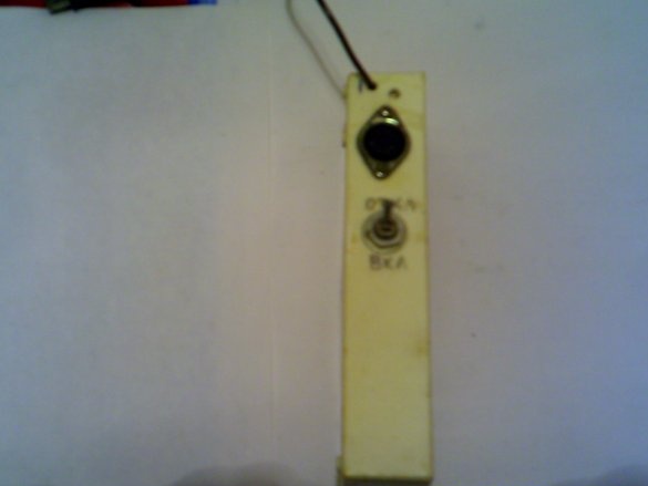
in my ready-made plastic case, I drilled two holes, and installed a connector and a toggle switch in them.
Step 3
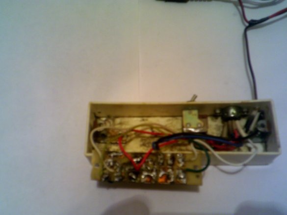
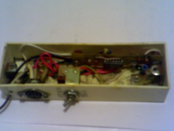
installed a printed circuit board in the case, using screws and nuts M3.
Step 4
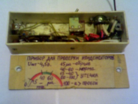
made the same side wall of the housing from the same plastic.
Inside the case I fixed two corners, and already on them I fixed the side cover with the help of two M4 screws. After this, I solder the circuit to the end.
Step-5 setting up the device
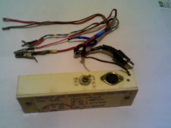
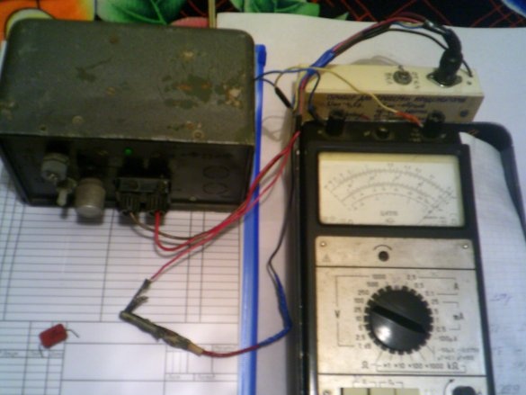
To do this, we need a pointer device Ts4315 or similar with a limit of measurement of direct current of 100 μa. I connect the device according to the photo to a 4.5v DC power supply, in my case to the power supply, and to the Ts4315 device according to the scheme.
The findings of the connector are indicated on the diagram by the numbers 1-6. When the SB2 button is connected to the 4.5V power supply, a current of about 15 μA flows through the indicator. If an operable tested capacitor is connected in parallel with the SB2 capacitor using the SB1 button, the current will increase and will be in the range of 40-60 μA, regardless of its capacity. These limits are considered normal and are marked in green on the scale. When checking capacitors with a capacity of more than 5 microfarads, the arrow of the device first deviates sharply towards the final division of the scale of 100 microns, and then returns to the limits of the segment. When checking oxide capacitors, their positive output must be connected to the socket XS1 (+). If there is an internal break, the arrow remains on the division of 15 μa.
If the capacitor is broken, the arrow will deviate beyond the final division. If there is a leak, the arrow will deviate beyond the segment if the leak resistance is less than 60 com. We are establishing this.Press SB2, make sure that the arrow deviates by 15 µa, if it does not match (15 - 20%), select R3. A 250 pF capacitor is connected to the sockets XS1 and XS2 and, by pressing two buttons at once, they notice the indicator readings. By selection of R2, the arrow is adjusted to a division of 50 μa (middle of the segment).
Having closed after this, the nests are convinced of the deviation of the arrow for the final division. I reduced C2 -20 pF, R1-1 com, C1 - 3300 pF now the device checks capacitors from 1 pF. How to connect the device to Ts4315 shown in the photo. This device has been working with me for 5 years, it is easy and fast for them to check capacitors.


