
Greetings the inhabitants of our site!
Surely you have a bunch of USB power sources at your place: power banks, charging for smartphones, and so on. As we know, very often Chinese manufacturers overestimate their real output characteristics. In order to evaluate and understand what a particular power supply unit or powerbank is capable of, as well as to approximately find out the capacity of the same power bank, without disassembling it, it is enough to have a usb tester on hand, with the ability to measure capacitance and a simple load (resistor, bulb and etc).
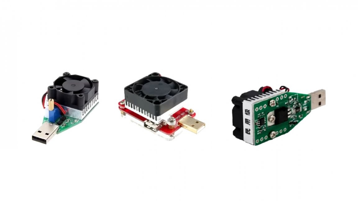
Of course there are specialized USB electronic loads for these purposes, and they seem to be not expensive, but buying what can be done at home is not our style.

More recently, the author (AKA KASYAN) received a batch of powerbanks of different sizes and characteristics.
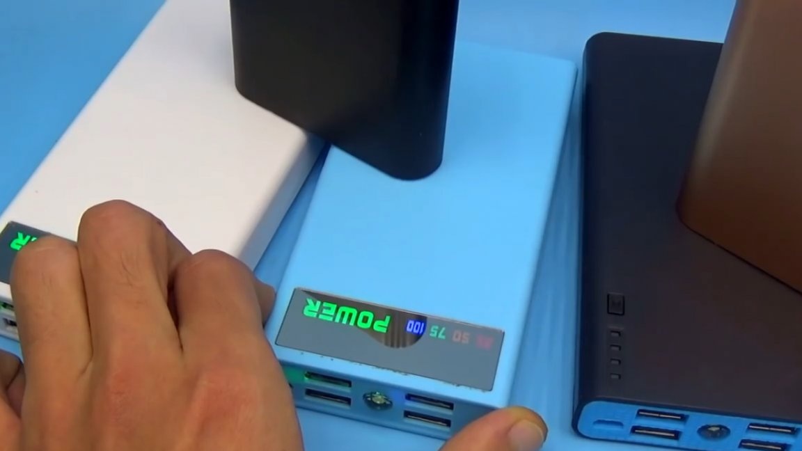
Assessing their actual output parameters of current and voltage is a matter of a few seconds.
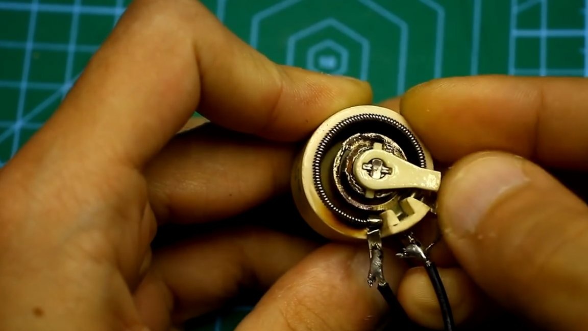
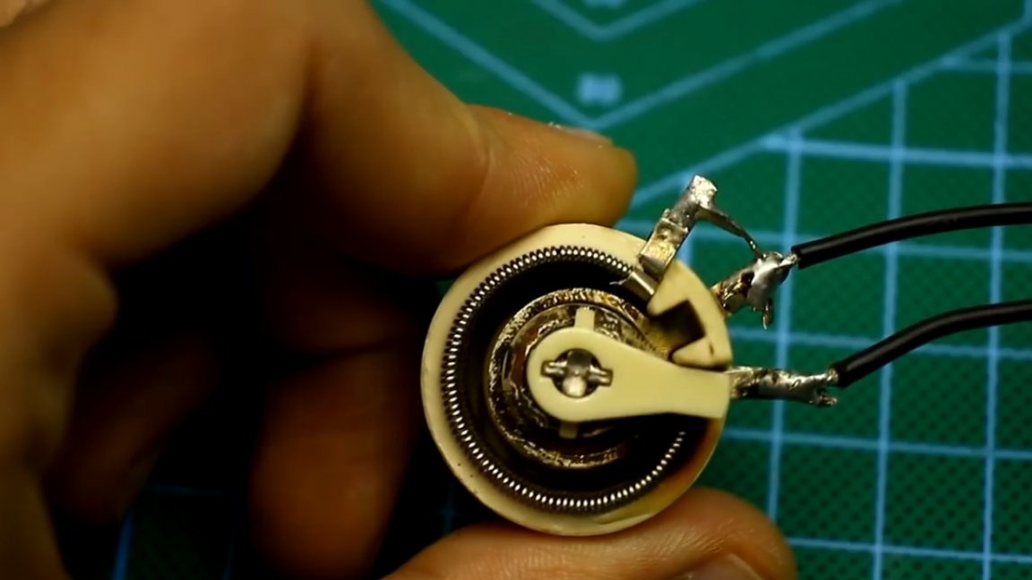
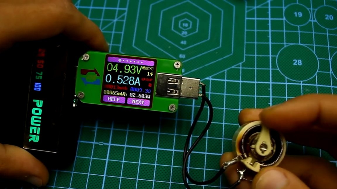
As a load, the author always used the good old wire variable resistor. It is enough to briefly load the powerbank with current up to 2A and, it would seem, it suits almost everyone, but on one harsh winter evening, he had nothing to do, sitting near the New Year's table, the author had the idea to make a USB electronic load.
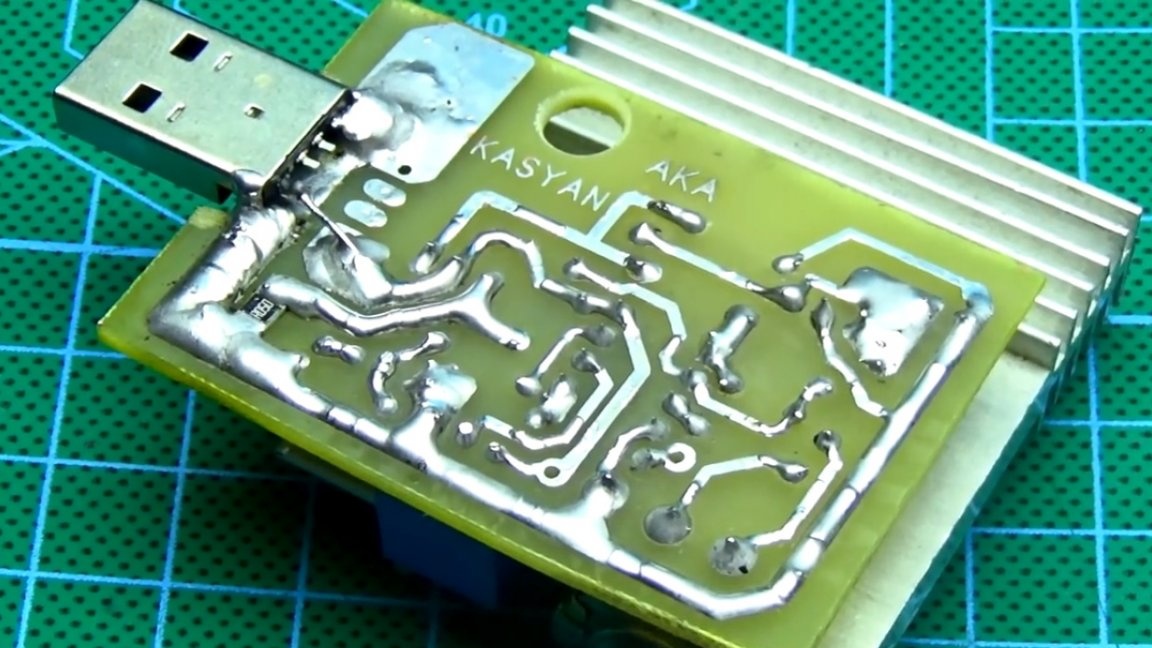
The scarf was designed in just half an hour.
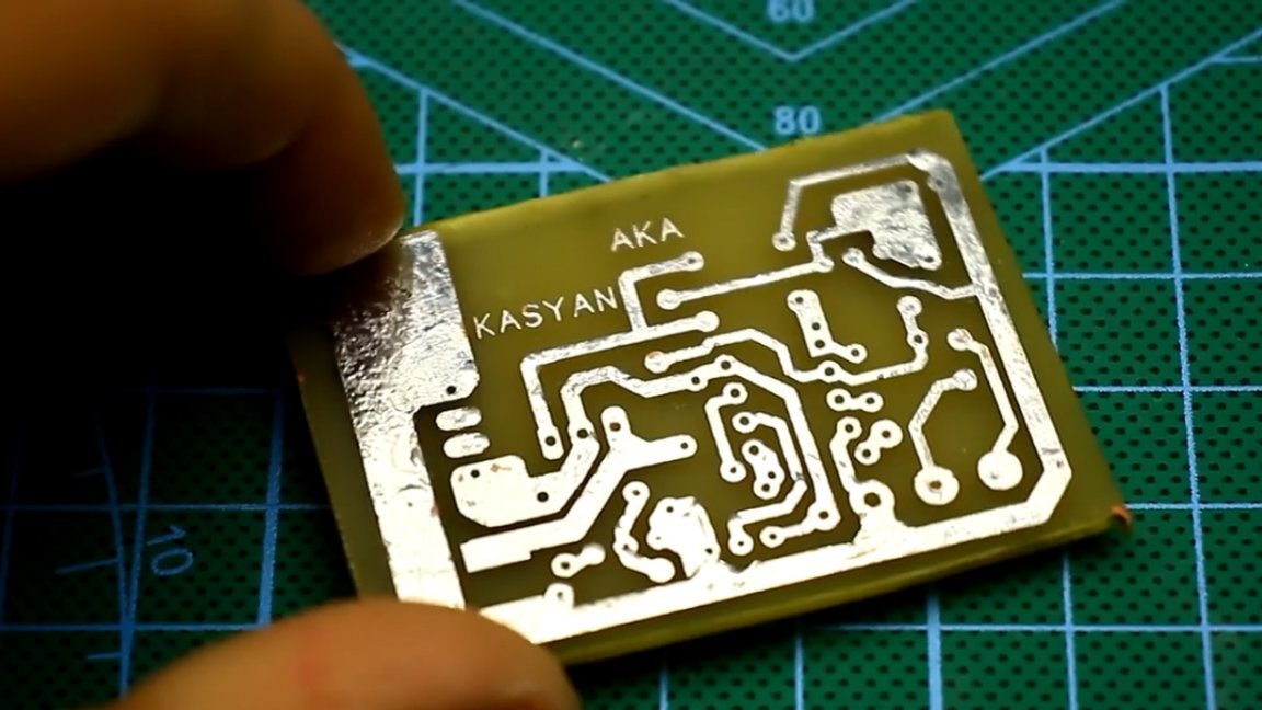
Another half an hour was spent on printing, transfer, etching, tinning and drilling. This is a rather time-consuming process.
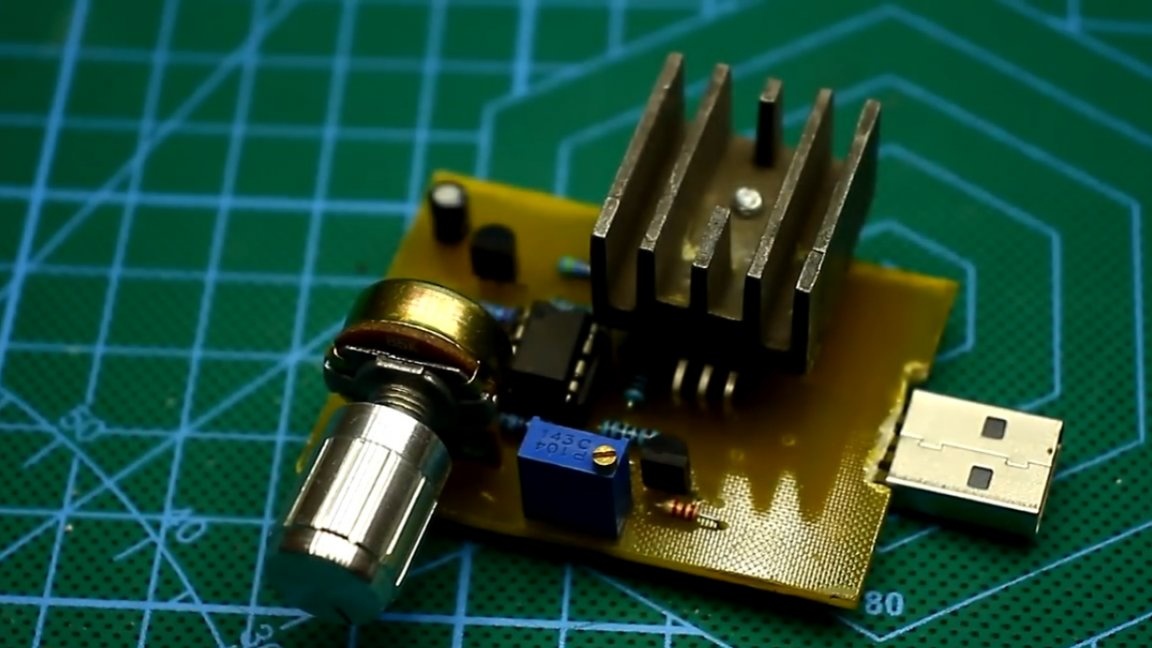
As a result, another, very good design was born that can be safely recommended for repetition.
To begin, let's look at the main characteristics of our current electronic load.
Operating voltage range from 4 to 15-20V;
The current adjustment range is from 0 to 5A, depending on the resistance and power of the current shunt;
Maximum rated power 20W, peak short-term up to 40W.
The load does not require an external power source, it is powered directly from the USB port that needs to be loaded.
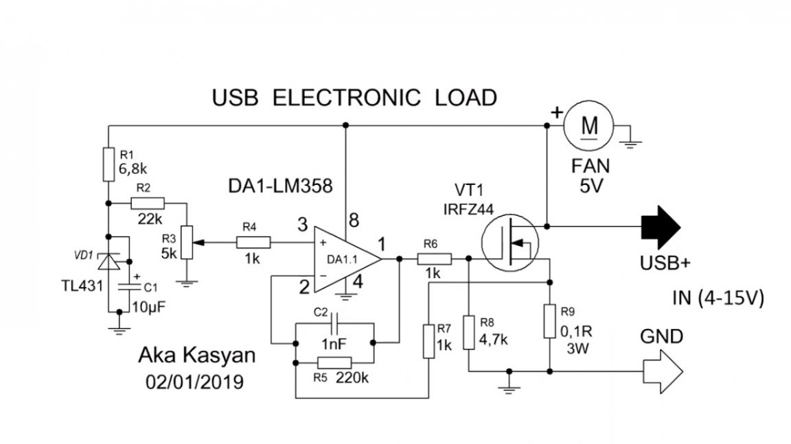
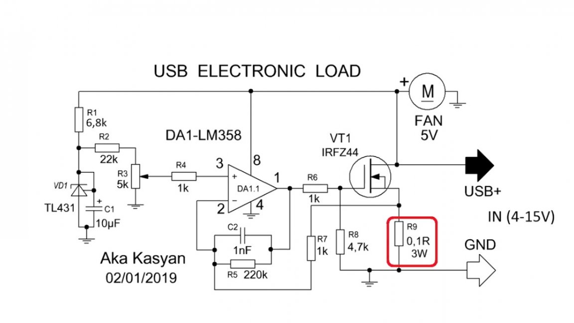
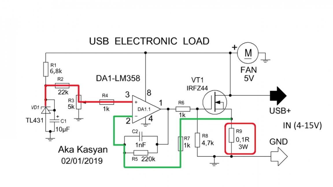
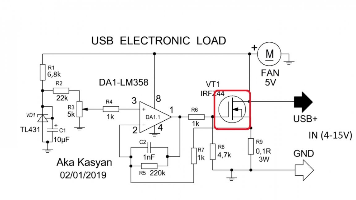
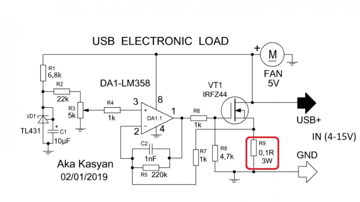
Let's look at the principle of a similar load, only at a much greater power. In a nutshell, we have an operational amplifier that compares the voltage generated by the reference source with the voltage that is taken from the current sensor in the face of a low-resistance resistor.
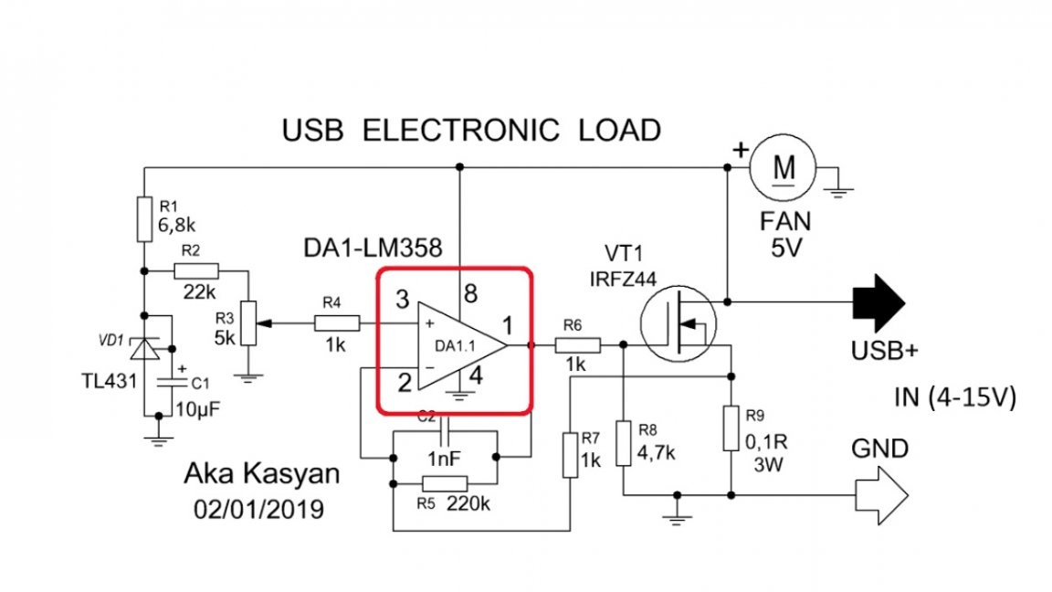
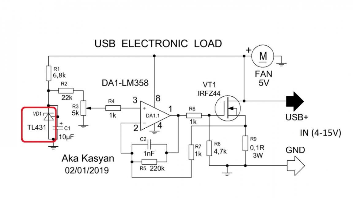
We have the ability to force change the voltage from a reference source by rotating a variable resistor.
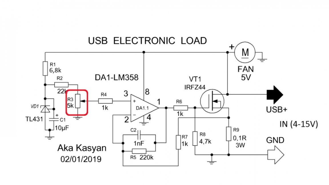
This violates the balance between the inputs of the operational amplifier, and he, in turn, by changing his output voltage, will try to balance the voltage between the inputs.
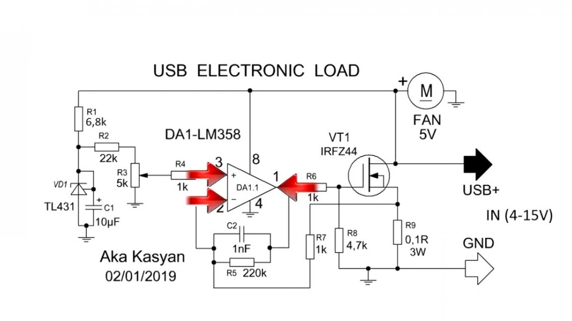
Changing the output voltage from the operational amplifier leads to a change in the resistance of the open channel of the transistor, and, consequently, to a change in the current in the circuit.
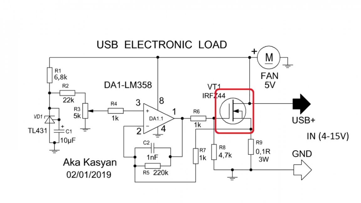
It is important to emphasize that this is a current stabilizer, and the set value will not change depending on the voltage, this is very important. All these advantages make it possible to use our load to discharge the batteries with a stable current in order to identify capacity. The range of supply voltages is quite wide. The voltage can be applied to the circuit up to 30V, but the author does not advise doing this, since violations in the operation of individual nodes are possible. The maximum permissible power dissipated by the load is 40W, but only if there is active cooling and a rather massive radiator for the transistor, and up to 20W for such a load is completely safe.
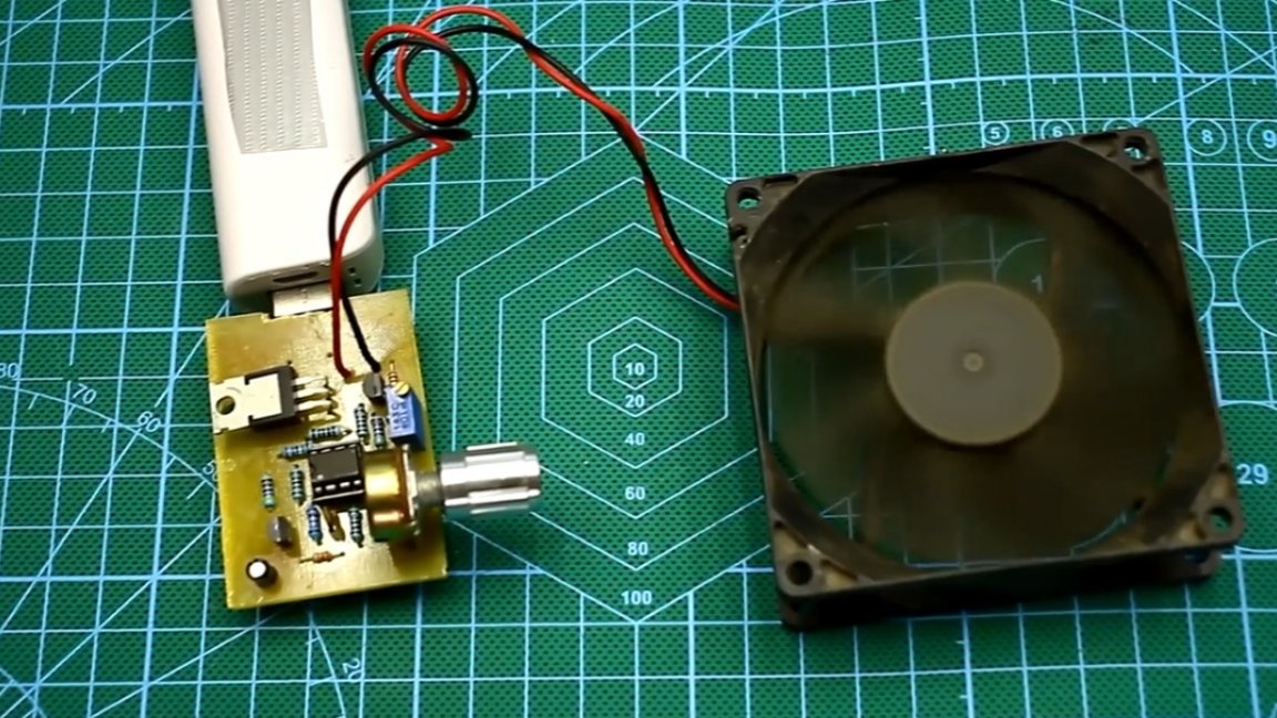
In order for the load to dissipate these 20W of power in the form of heat for a long time, again a small fan is needed.
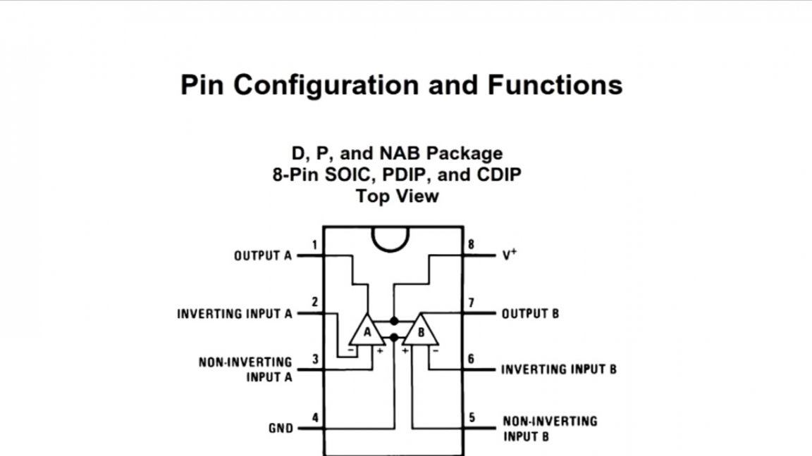
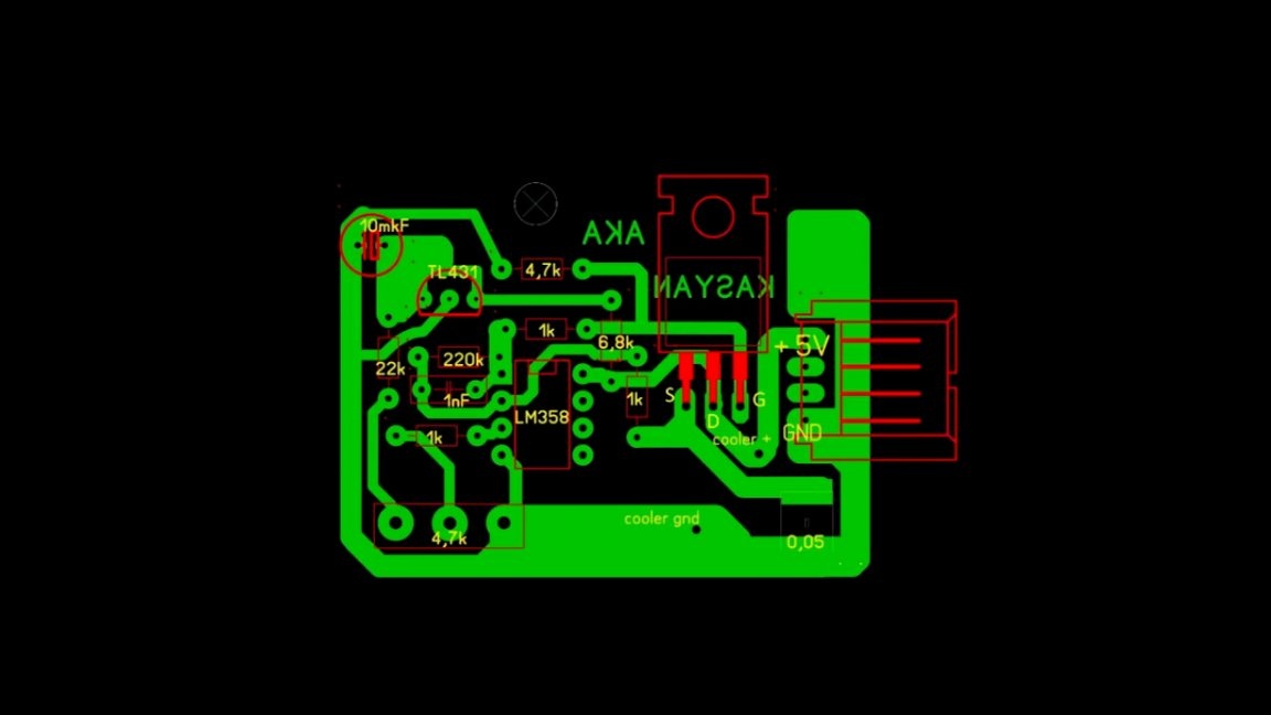
About cooling. Since the author used the lm358 dual operational amplifier chip, and the load circuit itself was built on only one element, the second channel remained free.
Without thinking twice, on the second element, the author decided to assemble a simple temperature regulator of the fan speed, which actually will cool our transistor.
If the transistor heatsink heats up above the set temperature, the fan will operate. Later, the author decided to completely abandon this site. It is better to solder the fan directly to the 5V line, it will constantly rotate. In the project archive, which can be downloaded from this one, you will find a board without a thermal adjustment unit.
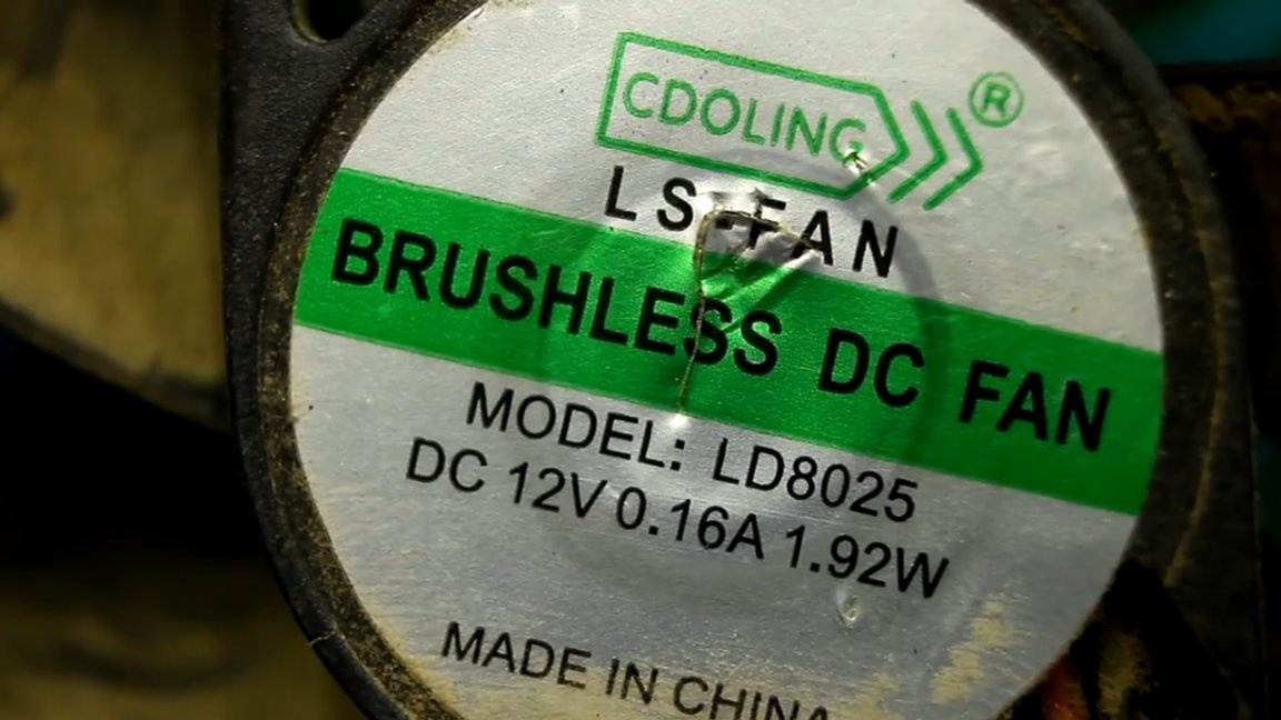
It is advisable to use a 5-volt fan, but conventional 12-volt also work well from 5V, so their use is allowed.
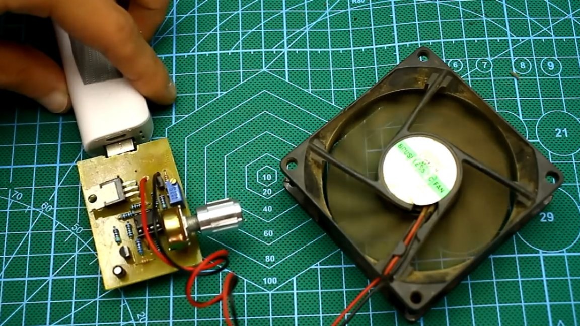
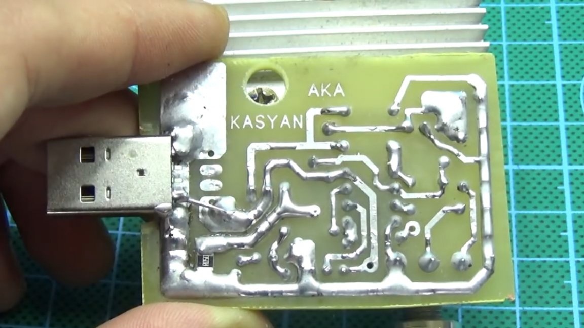
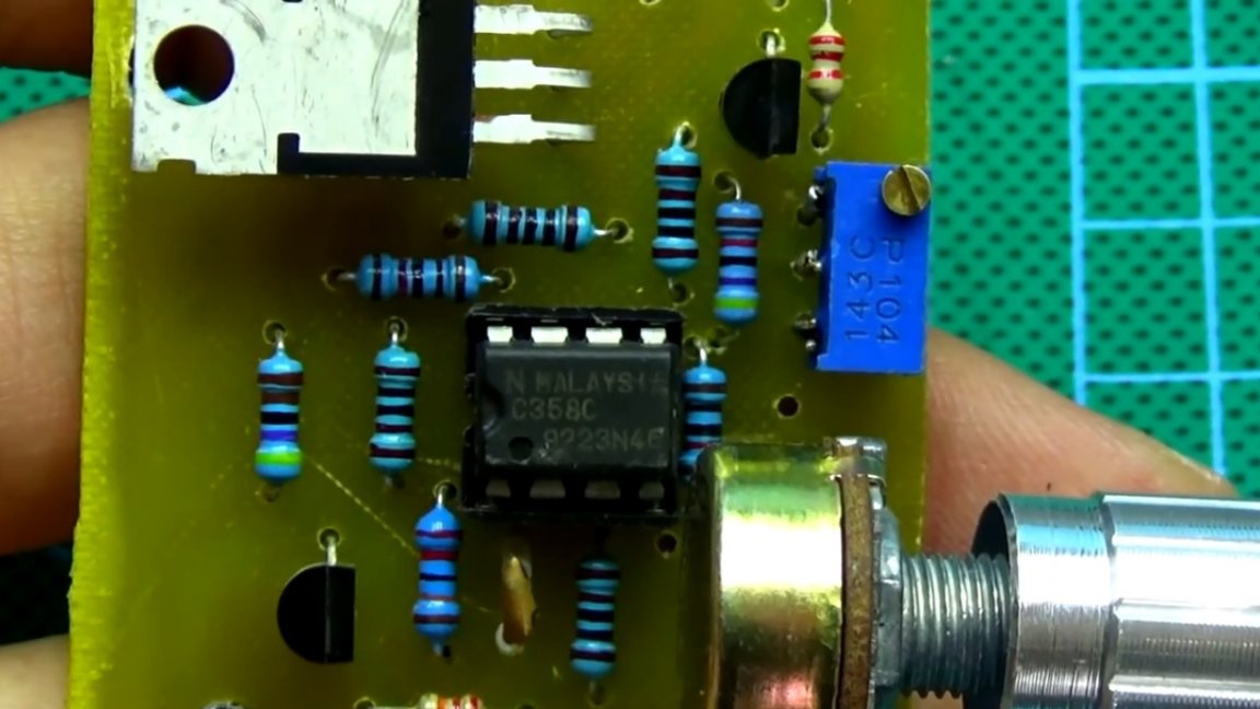
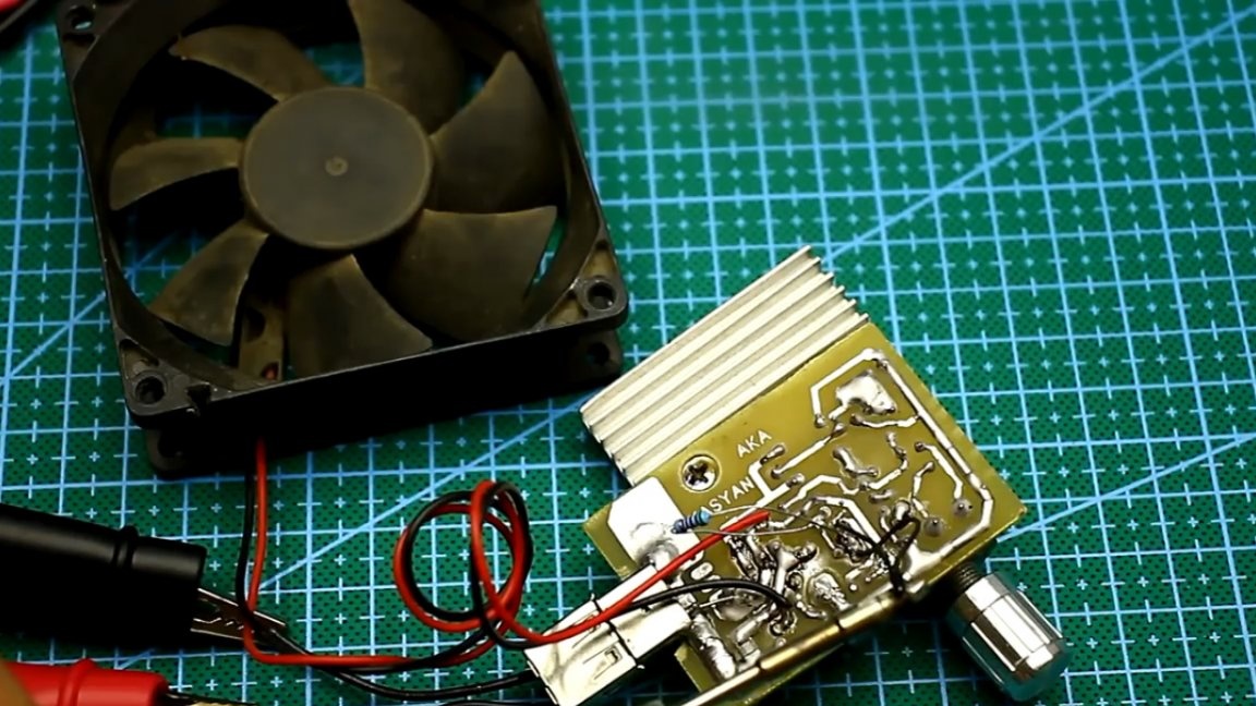
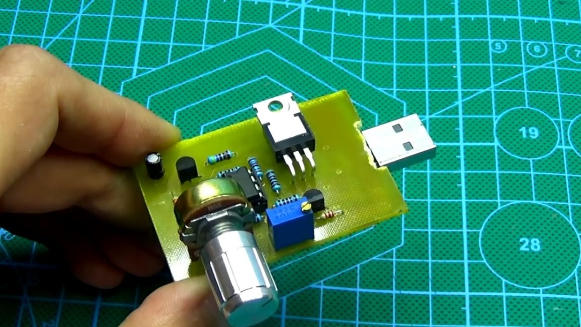
Of course, the fan needs a small-sized, and not the same as that of the author. Power paths of the printed circuit board author abundantly tinned solder.
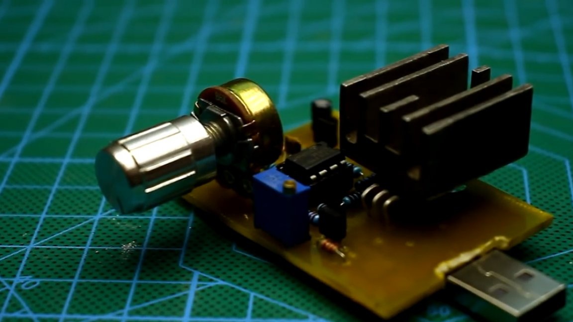
The transistor is screwed onto a small heat sink (this is a pilot option, in the future a larger radiator will be installed and all this will be cooled by a fan).
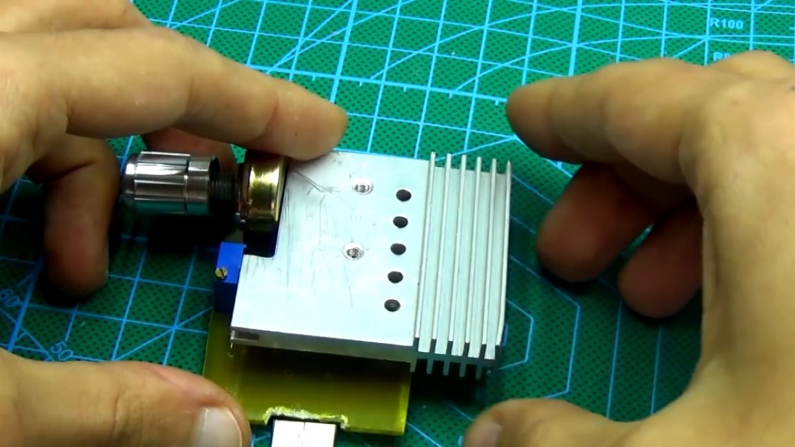
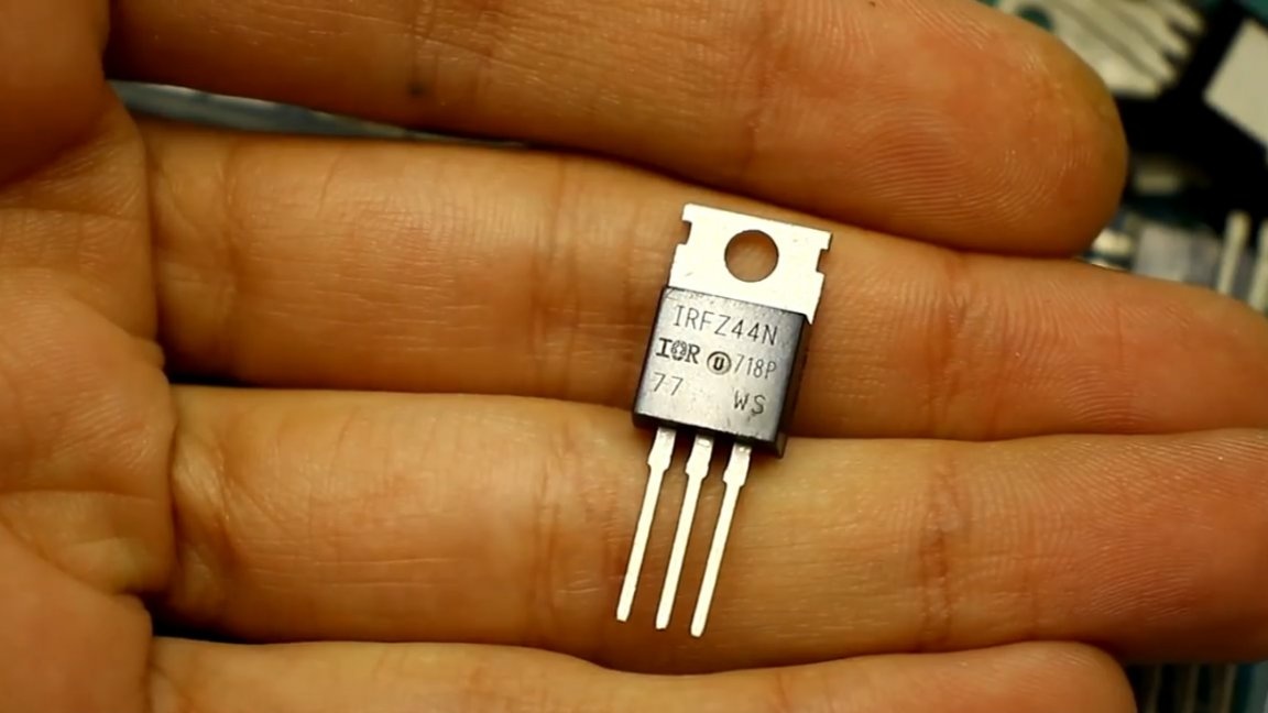
A power transistor, on which all power is dissipated in the form of heat - field. The load operates in linear mode and the transistor has a very hard time.
Current shunt.
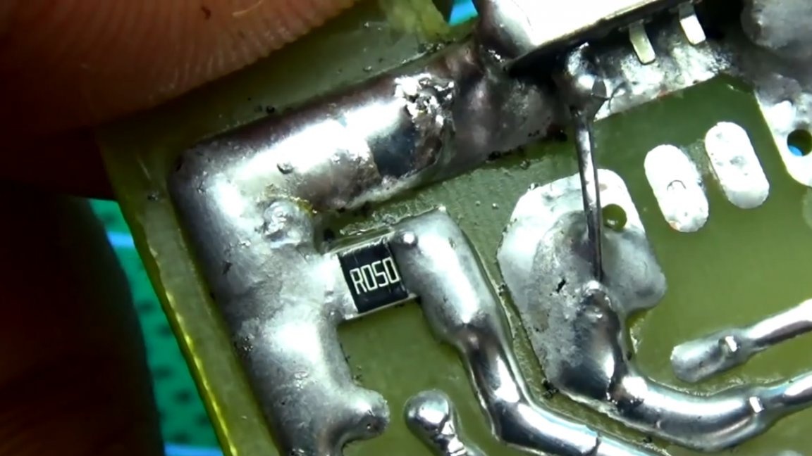
The maximum load current depends on its resistance and power. The author advises using 2-5W smd resistors with a resistance of 0.05 to 0.1 Ohm. If there are no powerful resistors at hand, then you can connect several pieces of lower power in parallel, or use ordinary low-resistance output type resistors.
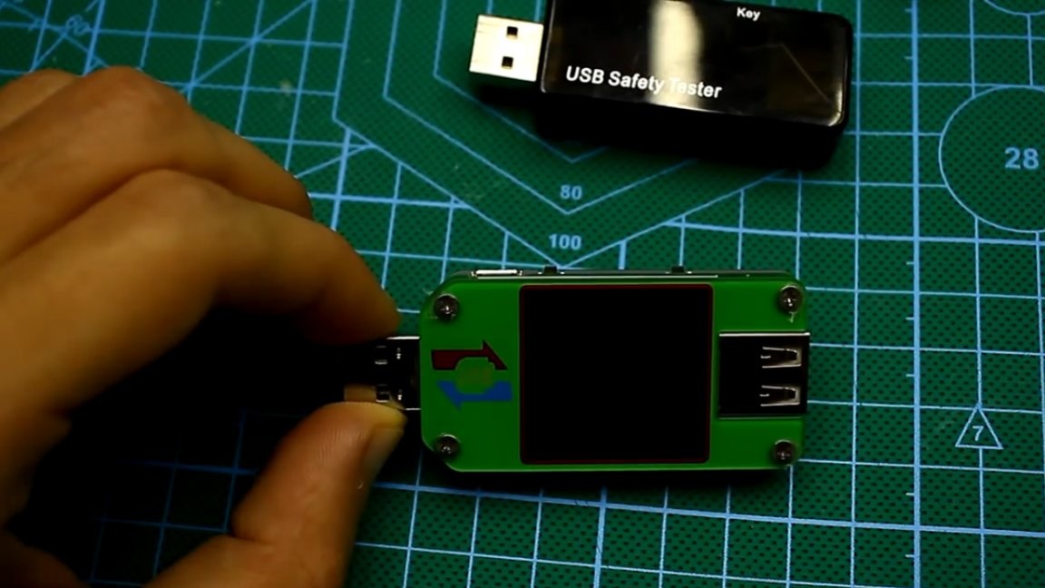
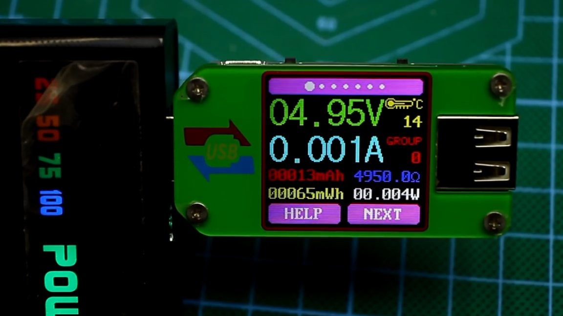
And now we’ll load a few power banks. The first sample has a capacity of only 2000mAh, power 1 lithium-ion battery standard 18650. We connect our load via a USB meter and smoothly increase the current by rotating a variable resistor on the electronic load board.
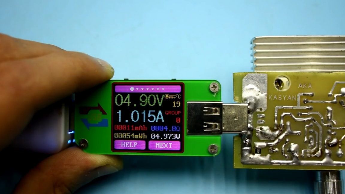
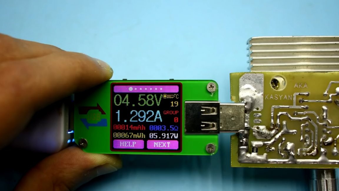
Powerbank output current is about 1A. When trying to get more current, the output voltage drastically drops.
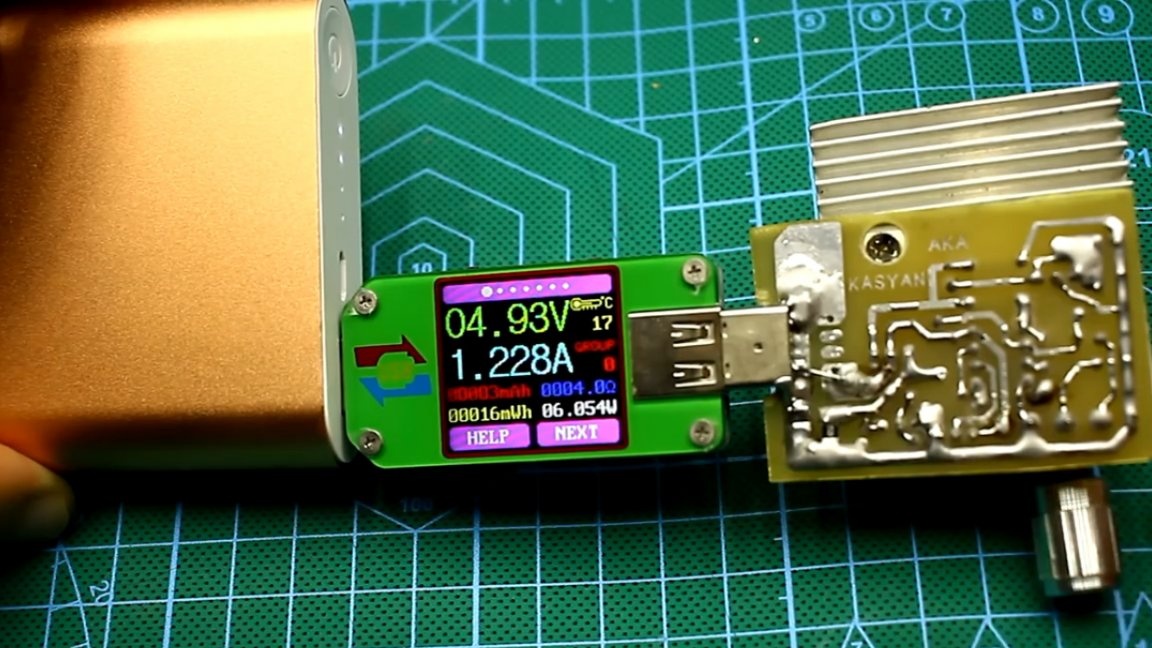
The second sample is more expensive, with a capacity of 10000mAh, power - 4 lithium batteries of 18650 format. We load the output in the same way. The output current is about 1.2A.
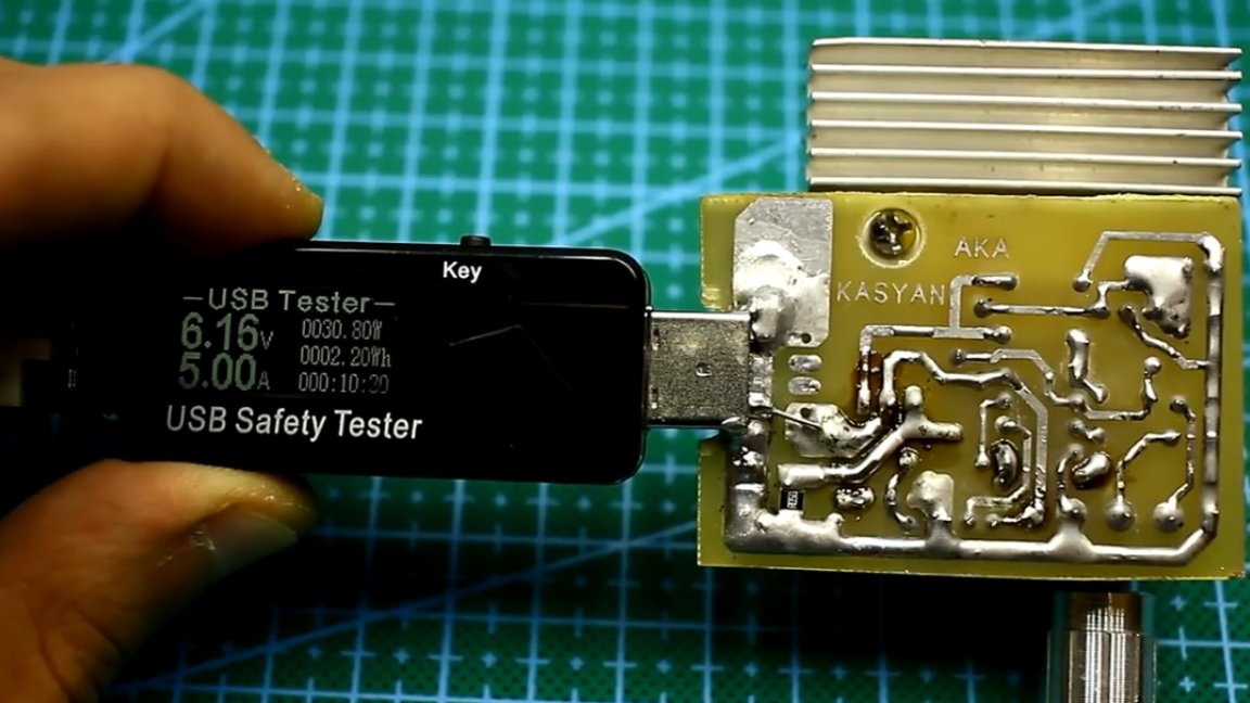
The third sample is powered by 6 batteries of standard 18650, the total capacity of about 15000mAh. The maximum output current is 2.6A. If you load even more, then the output voltage will drop.
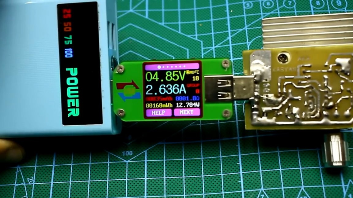
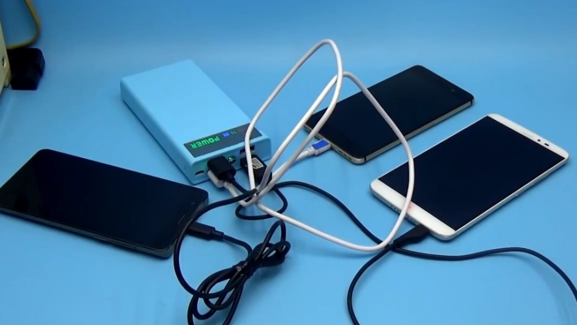
This powerbank is so far the best, whole 2, 6A. This is enough to simultaneously charge 2-3 smartphones or tablet.
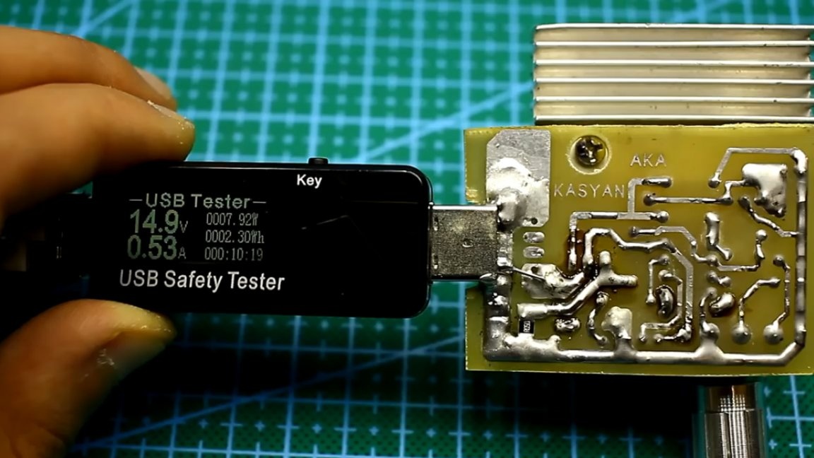
As already mentioned, with this load, you can check the output characteristics of the power supplies. Here is the quick charger 3.0 charger:
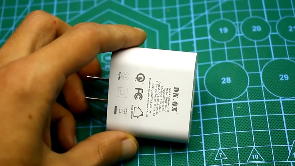
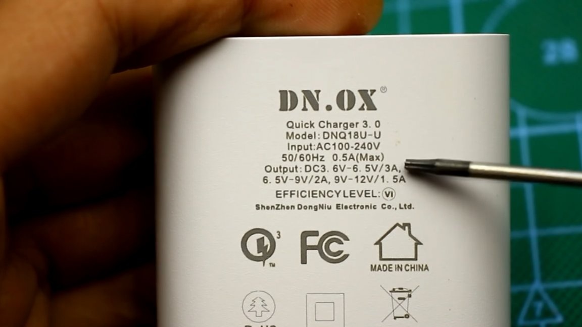
It can produce current up to 3A. Check if this is true?
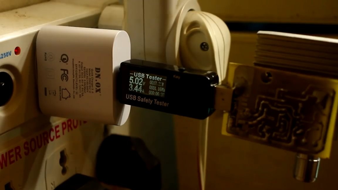
As you can see, the Chinese manufacturer again deceived, but in our favor. The adapter produces 3.5A instead of the declared 3A, and this is good news.
Well, that’s all. Thank you for attention. See you soon!
Video: