

This electronic An adjustable threshold fuse was invented by Instructables under the nickname GreatScottLab.
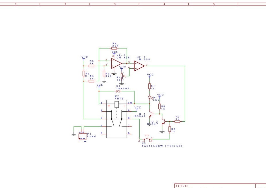
In series with the load, a shunt is included - a powerful resistor with a resistance of 0.1 ohms. The voltage to the shunt (almost independent of the load current) is applied to the non-inverting input of the first operational amplifier, and then (depending on this current is noticeably stronger) to the inverting one. The amplifier subtracts these signals, the result of which is supplied to the non-inverting input of the second operational amplifier, and voltage is applied to its inverting input from the movable contact of the tuning resistor. This amplifier works in comparator mode: instead of subtracting it, it compares the signals, switching abruptly. The tuning resistor allows you to set the threshold for the electronic fuse. Both amplifiers are located in the housing of one LM358 chip.
The circuit is constructed in such a way that the absence of overload corresponds to a logical zero at the output of the comparator. A transistor inverter turns it into a unit, and the key on the same transistor turns on the relay. Voltage is supplied to the load through its normally open contacts. When overloaded, the zero at the output of the comparator is replaced by a unit, which the inverter turns to zero. The key disconnects the relay and the load. A diode connected in parallel with the relay winding in reverse polarity receives the self-induction pulse that arises from this. After disconnecting the load, the current through the shunt ceases to pass, a logical zero appears again at the output of the comparator, but the relays with their normally closed contacts through the button also with normally closed contacts (in the diagram are erroneously shown as normally open) and the resistor supplies a logical unit to the inverter input, which makes the key does not return the relay to the on state.
Having eliminated the overload, the user presses a button whose contacts open, and the logical unit from the inverter input disappears.The relay turns on the load, and the device is ready again to eliminate the overload at any time if it appears. The device requires a restart with the button even after turning off and then turning on the power.
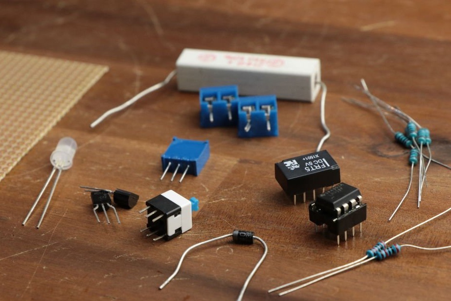
So, the wizard takes all the components necessary for assembly homemade:
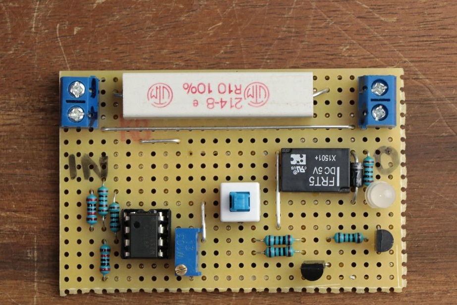
Installs them on a piece of a perfboard type breadboard:
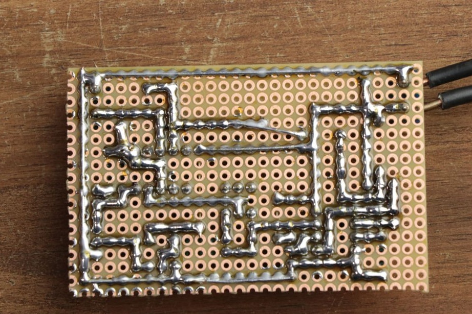
The terminal blocks are very convenient for connecting the power supply and the load, but when working with constant voltage, you should remember the polarity. Therefore, it is good to put the appropriate markings on or near the terminal blocks. And the input and output on the board, as we see, are already marked. The master connects the components together by soldering:
To verify the design, it is necessary to turn on the load through it and set the trim threshold so that it only slightly exceeds the current consumed by the load. Then connect another less powerful one in parallel to the load. The relay should trip.