It is proposed to make a charger for the battery, with current stabilization, adjustable for current and voltage at the load. The range of application is extensive. One of the options for its use is considered in a particular example.
In the manufacture and installation of the car radio unit in home setting "Using the car radio in the home version"One small problem was discovered. It lies in the fact that in the manufacture of the radio, non-volatile memory was not yet widespread. And auto-search for stations has already been used. Therefore, to save the settings in the receiver's memory, additional power was required for the memory cells when the receiver was turned off. IN car, This was solved by constantly connecting the memory unit to the battery of the on-board network. When installing a car radio in the apartment, I had to look for a way out.
It is not possible to use three-volt batteries to power the memory cells, similar to saving memory in a computer. To power the memory unit in the car radio (according to the instructions), 3.1 ... 3.5 volts are required.
When installing the battery, there is a problem. We have to monitor the state of the battery charge and periodically removing it to recharge, which is inconvenient and not practical. Therefore, in my opinion, it is easier to permanently install a battery in the manufactured unit of the car radio, make a charger for it and install it in the same place.
As a result, the task was as follows. It is required to make a charger for the battery, with regulation and stabilization of the current, with a limitation on the maximum voltage on the battery of 3.6 volts. The battery should be charged automatically and only when the receiver is turned on, and keep its memory constantly. To exclude a complete discharge or overcharge, the charging modes must be adapted to the degree of discharge of the battery, i.e. The charger should be adaptive (to the extent possible).
Charger circuit.
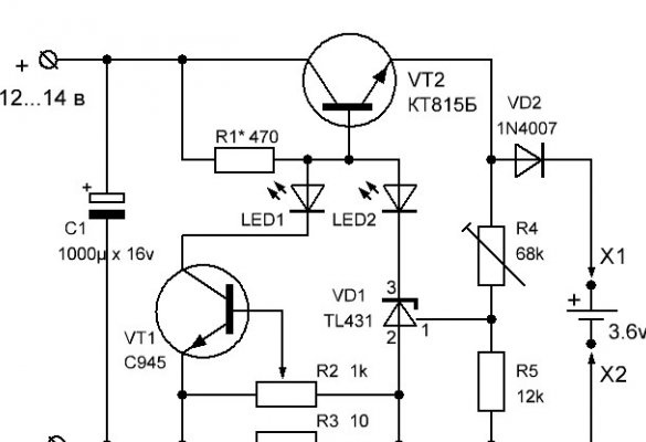
The charger circuit is characterized by maximum simplicity and accessibility of components, it basically contains two transistors and an adjustable zener diode. The low-power control transistor VT1 performs the function of regulating and stabilizing the current. The transistor VT2 is power, the main battery charge current flows through it. Also, the charger contains an output voltage regulator on the zener diode VD1.
Output voltage regulator
The basis of the voltage regulator determines the controlled Zener diode VD1 - TL431. Voltage regulation on TL431 is carried out using a voltage divider R4, R5. By selecting the values of these resistors, we achieve the necessary adjustment range. Then, by changing the resistance of the tuning resistor R4, before installing the battery in the charger, we set the maximum charge voltage (3.6V) at the output contacts X1 and X2.
When the discharged battery is connected to the charger, the voltage at the output contacts drops and the battery starts to consume, the current set with resistor R2 and limited by resistor R3. When the battery voltage approaches the output voltage set by the regulator, the charge current will decrease and when the voltage on the battery reaches 3.6V, the charging current will be practically zero.
This happens for the following reason. The controlled zener diode TL431 is closed until its control electrode has a voltage below 2.5V and does not affect the operation of the charger. When charging the battery and approaching the voltage on it, to the output voltage previously set by the regulator, the potential at the control electrode reaches 2.5V and the zener diode TL431 starts to open. In this regard, the power transistor VT2 begins to close, and the charging current flowing through it will gradually decrease to almost zero.
Thus, we limit the maximum voltage on the battery to a predetermined one and exclude its recharge, transferring charging to the drip mode (0.005C), which only supports memory and compensates for battery self-discharge.
Current stabilizer
The current stabilizer maintains a stable output current to charge the battery while eliminating the influence of the voltage regulator.
The operation of the current stabilizer is controlled by the transistor VT1. The current limit limits the resistor R3. It is a low-resistance resistor from 0.1 to 20 ohms (depending on the required power of the charger) and at the same time is a current sensor. When the load is connected, a certain voltage drop is formed on this resistor, proportional to the passing current. Such a voltage drop is enough for the operation of the control transistor VT1.
With an increase in current, for some reason and a corresponding increase in the voltage drop across R3, the transistor VT1 opens more. In this regard, the power transistor VT2 begins to close, and the current passing through it to the battery decreases.
When current decreases through the load, the opposite is true.
Thus, the transistor VT1 automatically controls the power transistor, adjusting the current flowing through it and the load, so the current stabilization process is carried out.
At the first stage, the charge is carried out by a stable current (manually selected). When the set voltage on the battery is reached (manually selected), the charge continues while maintaining a stable voltage and decreasing value of the charge current.
By changing the resistance of the resistor R2, it is possible to manually set the required battery charging current.
The resistor R1 sets the bias voltage for the power transistor VT2, and also determines the operating current of the zener diode VD1. By selecting R1, the zener diode current is set within 5 ... 10 mA.
The LEDs in the device are used to visually signal the charge process. The glow of the LED1 indicates the operation of the current stabilizer, and LED2 the operation of the voltage regulator.
As the control (power) NPN transistors, it is possible to use both domestic and imported low-power (medium power) transistors, with the corresponding current and voltage characteristics. The VT2 power transistor will heat up under heavy loads and needs to be installed on a radiator. The VD2 diode protects the battery from discharge when the receiver and the charger are turned off. The battery leads are connected to the receiver memory unit.
Charger manufacture
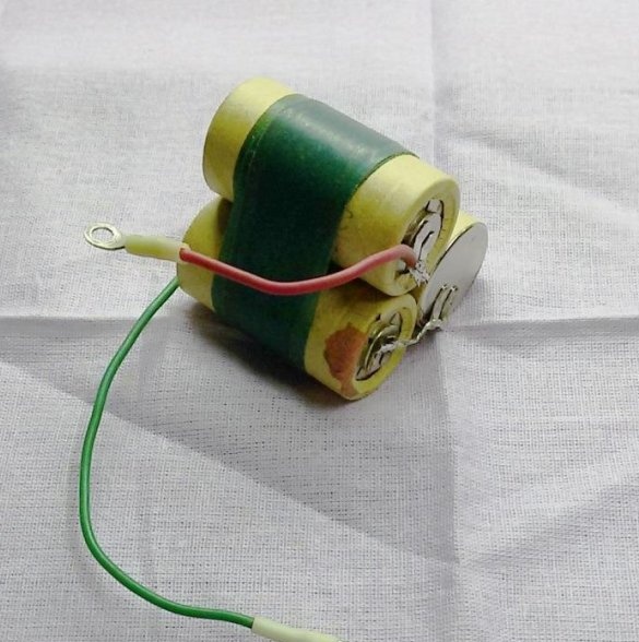
1. Battery selection
To power the memory unit in the car radio, we use three series-connected NiMH batteries with a total nominal voltage of 3.6 volts (1.2 x 3) and a capacity of more than 2.0 Ah. The discharge of each battery element is allowed up to 0.9 volts, and the entire battery up to (0.9 x 3) 2.7 volts. A full battery charge is possible up to (1.8 x 3) 5.4 volts. Thus, by setting the voltage regulator of the charger to 3.6 volts, we are guaranteed to exclude recharging the battery without even disconnecting it from the device.
There is also some protection regarding the full discharge of batteries. With a supply voltage of 3.0 volts, the auto search settings in the receiver are lost, which is noticeable the next time you turn it on. The minimum charge in the battery still remains. In this case, the operation of the device needs to be adjusted. To do this, you only need to slightly increase the charging current.
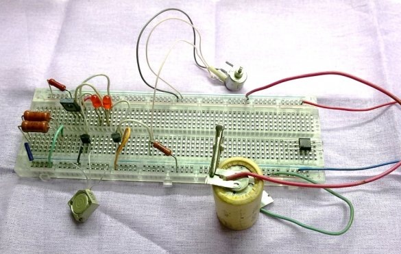
2. Assembly and verification of the operation of the circuit
We select the details according to the above diagram. Assembling the charger circuit on a universal circuit board. We check the operation of the circuit by setting the battery element as the load. Choosing the values of the resistors R4, R5, we achieve the ability to adjust the output voltage in the entire range. Having installed the entire battery of the batteries, we check the possibility and values when adjusting the charging current. With a rating of R3 according to the above diagram, the current is regulated from 0 to 350 mA with an output voltage of 3.2 to 9 -11 volts.
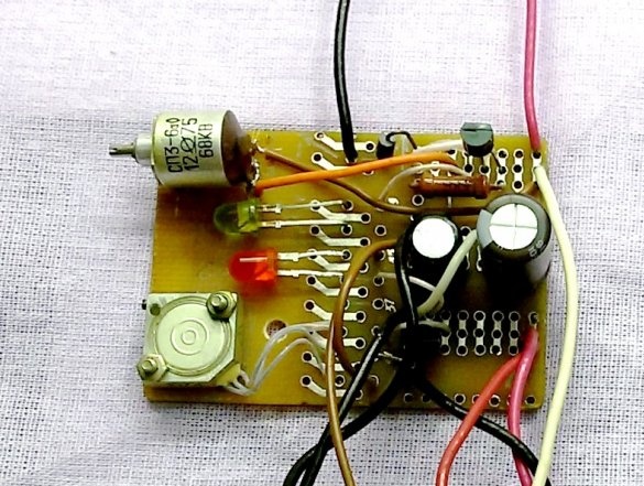
We cut out from the universal board and prepare a working board for assembly.
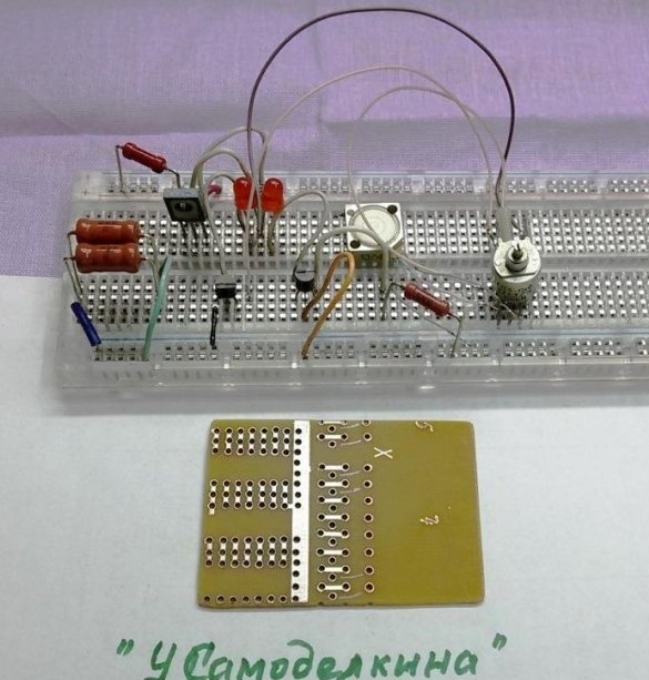
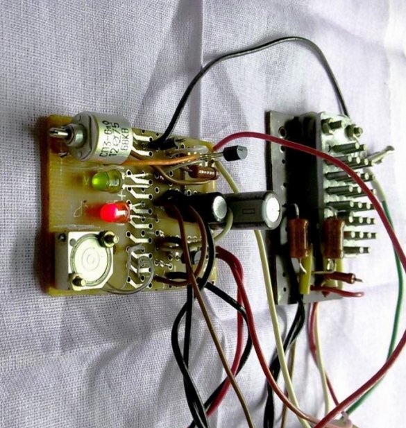
3. We carry out the installation of the circuit on the working board.
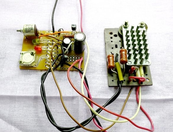
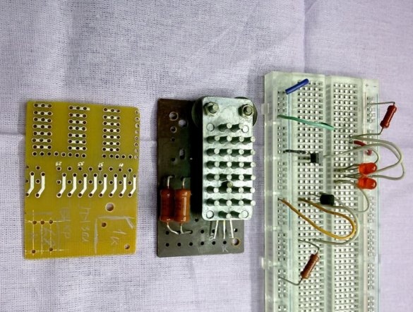
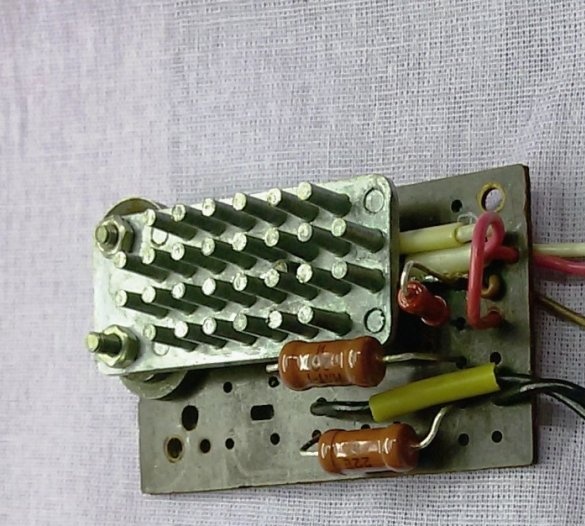
If there is free space and to improve the temperature regime of the parts, it is possible to distinguish from the circuit a block of parts having a large heat emission. In this case, it is a power transistor on the radiator and resistor R3 (made up of two lower power connected in parallel). These parts are assembled on a separate option board installed away from the master board. The remaining parts are assembled on the main board.
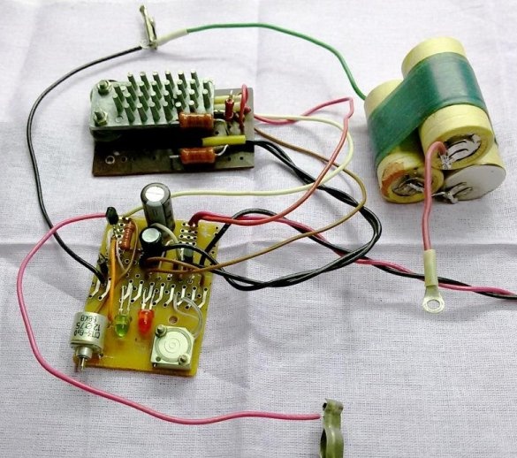
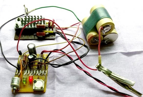
4. Final assembly.
We assemble the entire circuit in the working version and check the operation of the assembled charger.
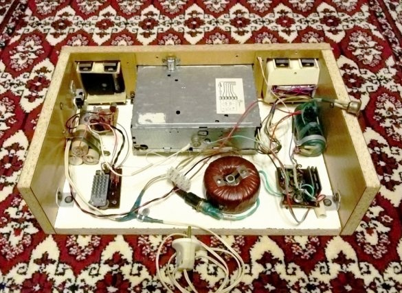
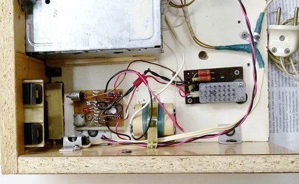
We install the working circuit in the previously manufactured radio unit in the home version. Since the unit of the car radio is stationary and its removal is a laborious task, the drive board of the device is located in the unit’s case, near the window under the kitchen clock. When removing the clock from the window, which takes 3 seconds, access to the operation indicators and the adjustment of current and voltage is free.