
Greetings the inhabitants of our site!
If you are a radio amateur, then you must have tried to assemble a powerbank do it yourself, at least for sports interest. But to a greater extent, people make power banks with their own hands for the reason that factory portable charging does not suit them with something. Take even the fact that the charging current of such powerbanks rarely exceeds a value of 1A (here it means the current charged by the powerbank itself, and not the output current with which it (powerbank) charges your gadgets).
So, 1A is not enough and, for example, if the capacity of a powerbank is impressive and amounts, for example, to 20,000 mAh, then it will charge about 20 hours or more with that current, to say nothing of power banks with a higher capacity.
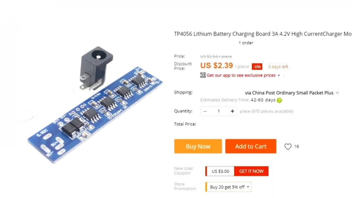
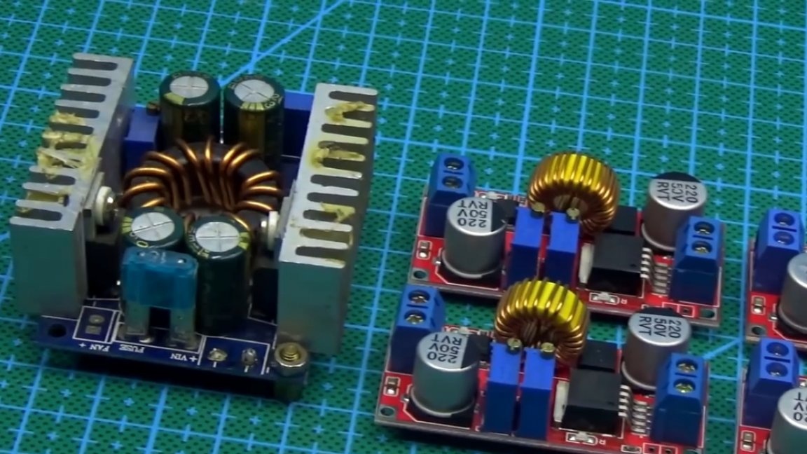
Charge cards for one can of a lithium-ion battery based on TP4056 chip are familiar to everyone.
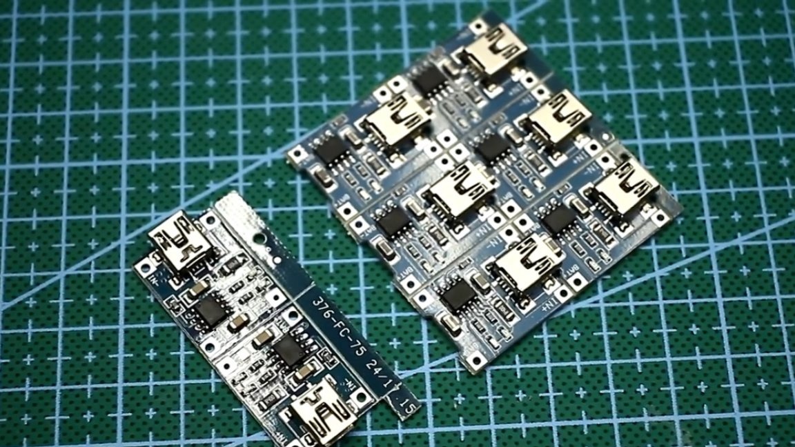
They can charge a lithium battery with current up to 1A. The Chinese are now selling 3 amp versions of such boards.
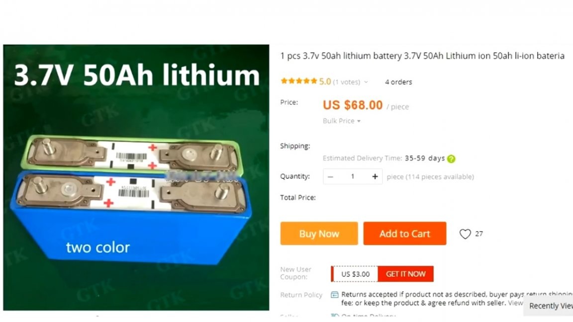
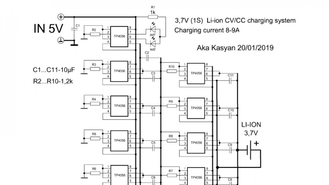
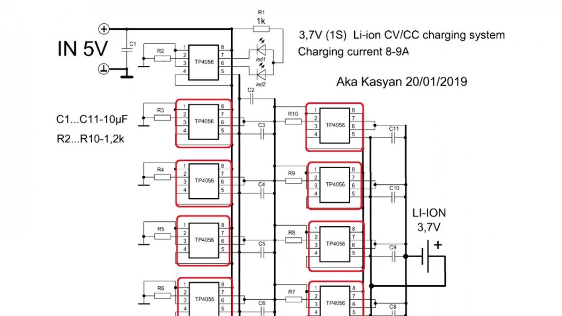
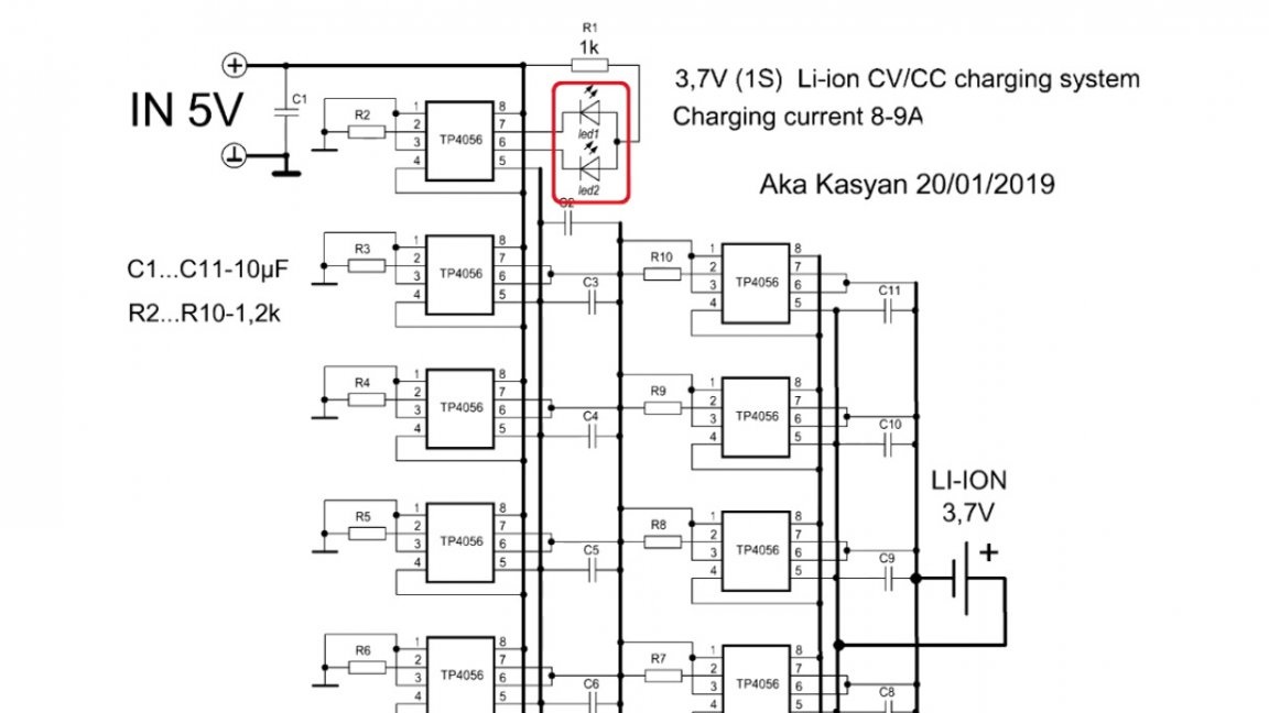
So, the author of today's homemade product (AKA KASYAN), decided to cross 9 TP4056 microcircuits. This will make it possible to charge lithium batteries with a current of up to 8-9A. Why is this needed? Well, firstly, such a board will be very useful if you decide to assemble your own large-capacity powerbank, and secondly, powerful lithium-ion banks with a capacity of 80,100 or more ampere hours are on sale now and they need powerful charging systems.
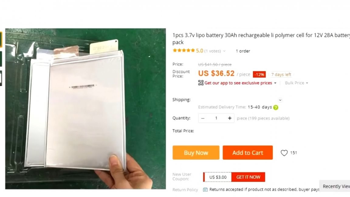
As we know, there are many options for charging powerful lithium cans, but the TP4056 chip remains the cheapest of them.
Each chip is 1A. Connect as many chips as you like, thereby getting a charger for any desired current.
The chip of the TP4056 chip is that it charges the battery with the correct method, that is, stable current and voltage.
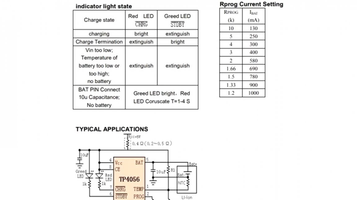
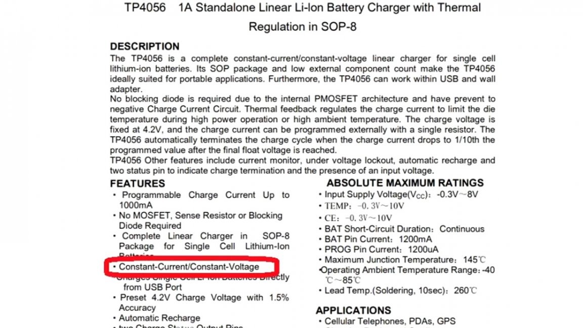
As soon as the battery voltage reaches 4.16-4.2V, the charge stops.
Let's get back to our scheme. The author needs such a charge precisely for a very capacious power bank, he was asked to make one friend who is engaged in tourism and leads people on long hikes, but this is another story.
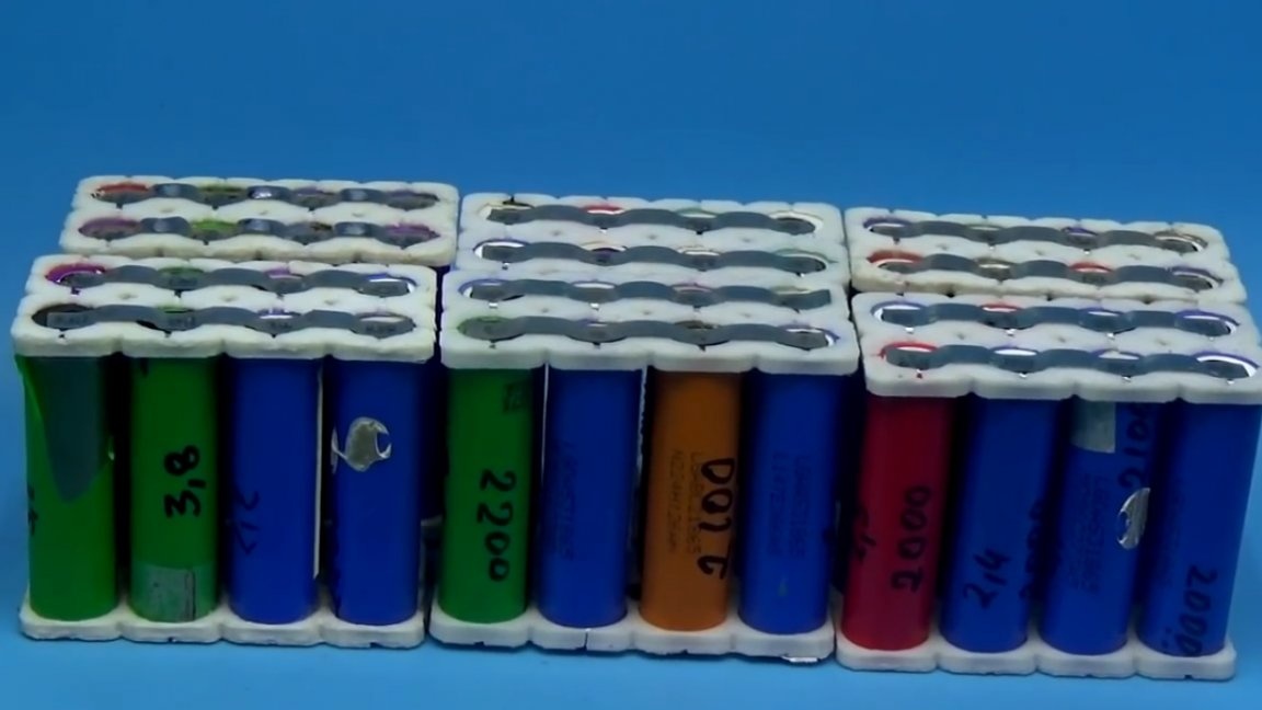
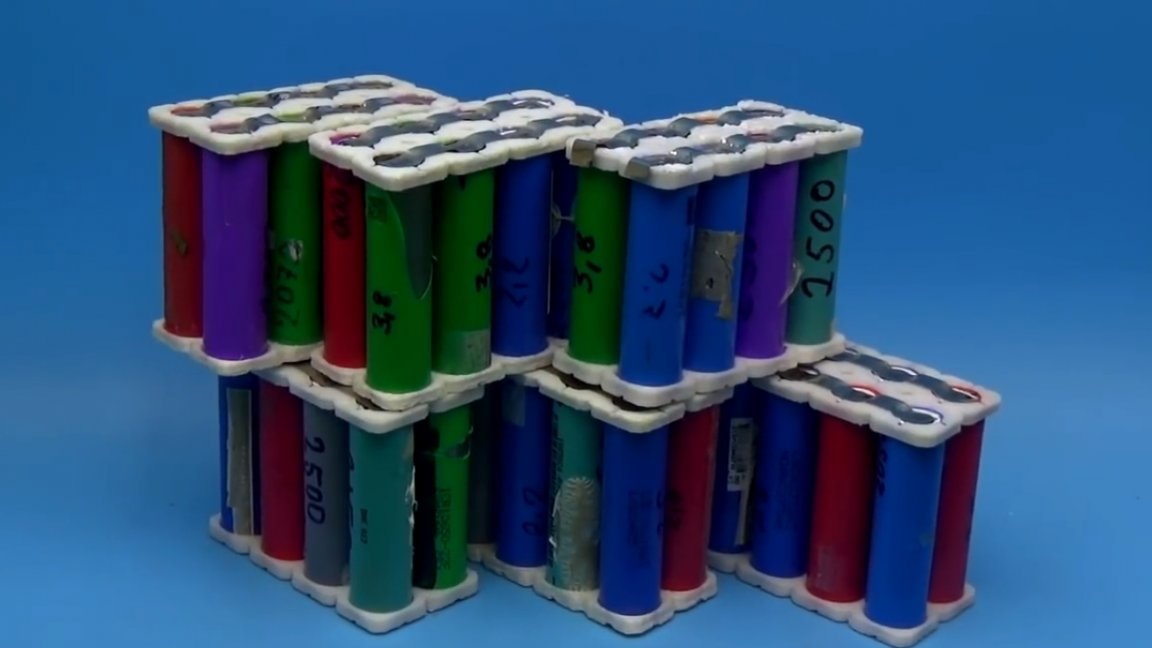
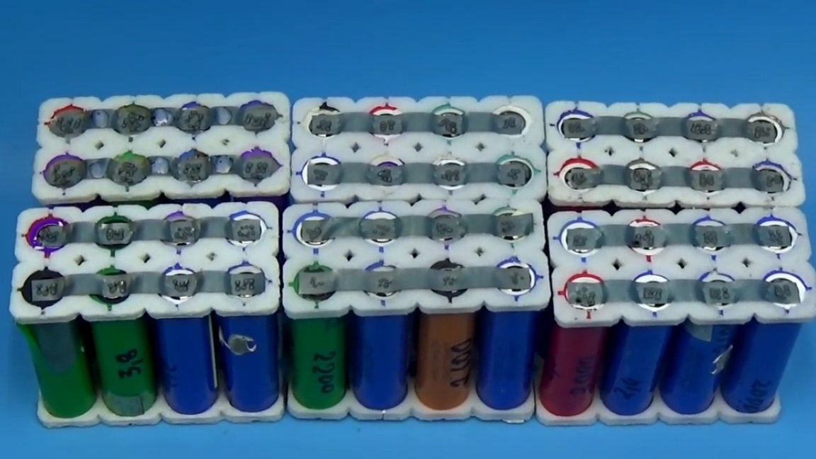
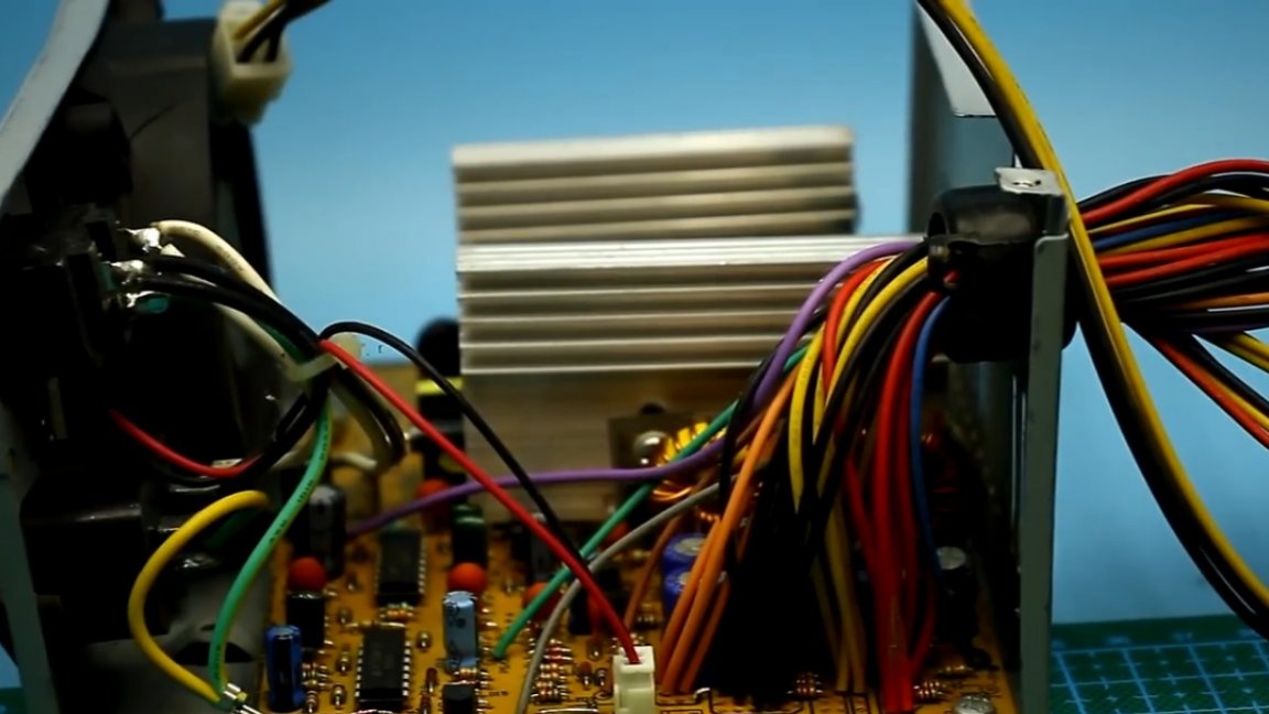
Powerbank is planned for 100,000 mAh and it’s impossible to charge such a thing, of course, from a regular USB port. More precisely, it will turn out if you wait about 5 days, therefore, the author intends to charge the assembly of 48 lithium cans of the 18650 standard from the 5-volt bus of the computer power supply, he will calmly give out currents of 10 or more amperes.
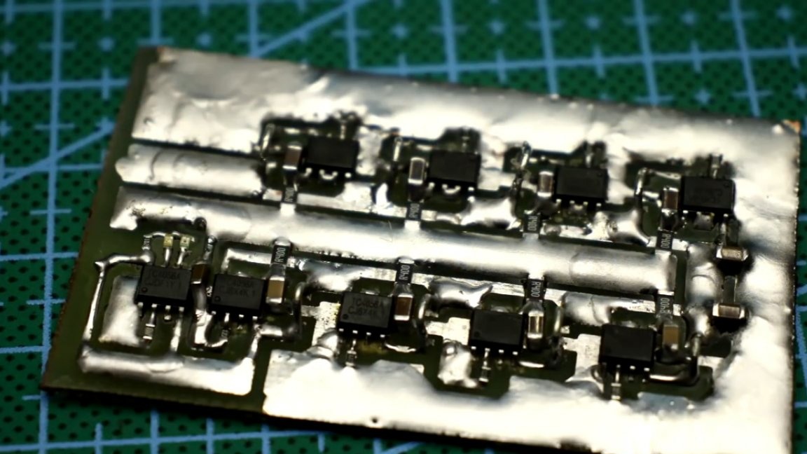
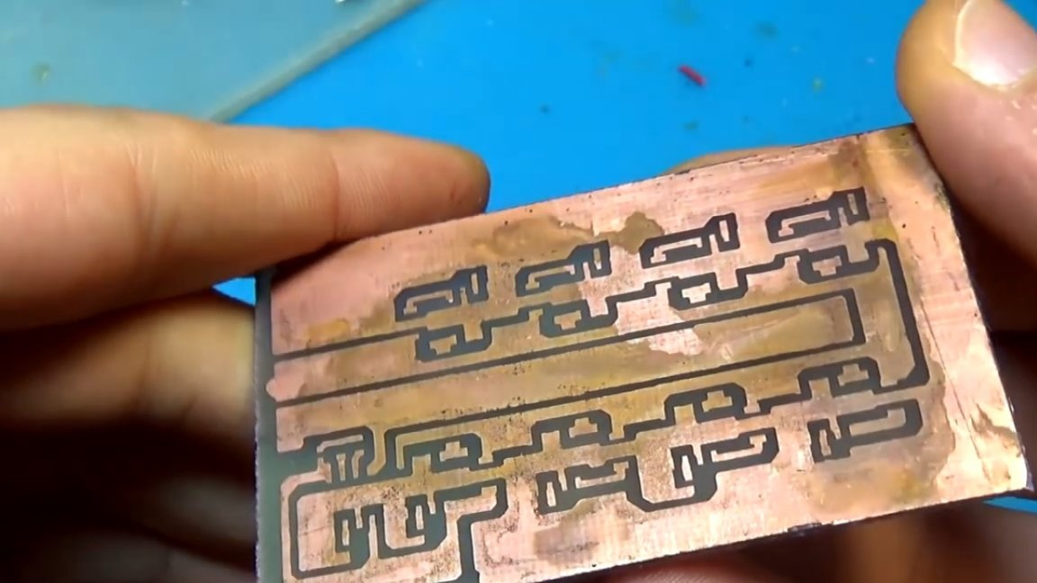
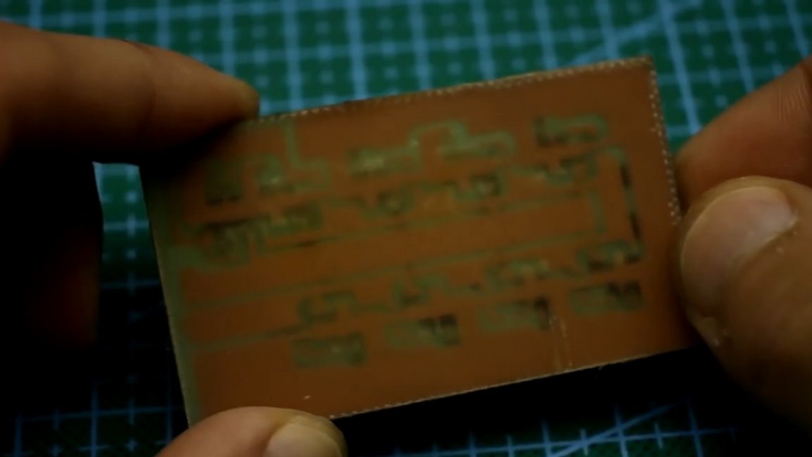
About the circuit board.It, as always, along with the general archive of the project can be downloaded from the link in the description of the author’s video (the SOURCE link at the end of the article) or. The author previously mirrored it; all that remains for you to do is print it.
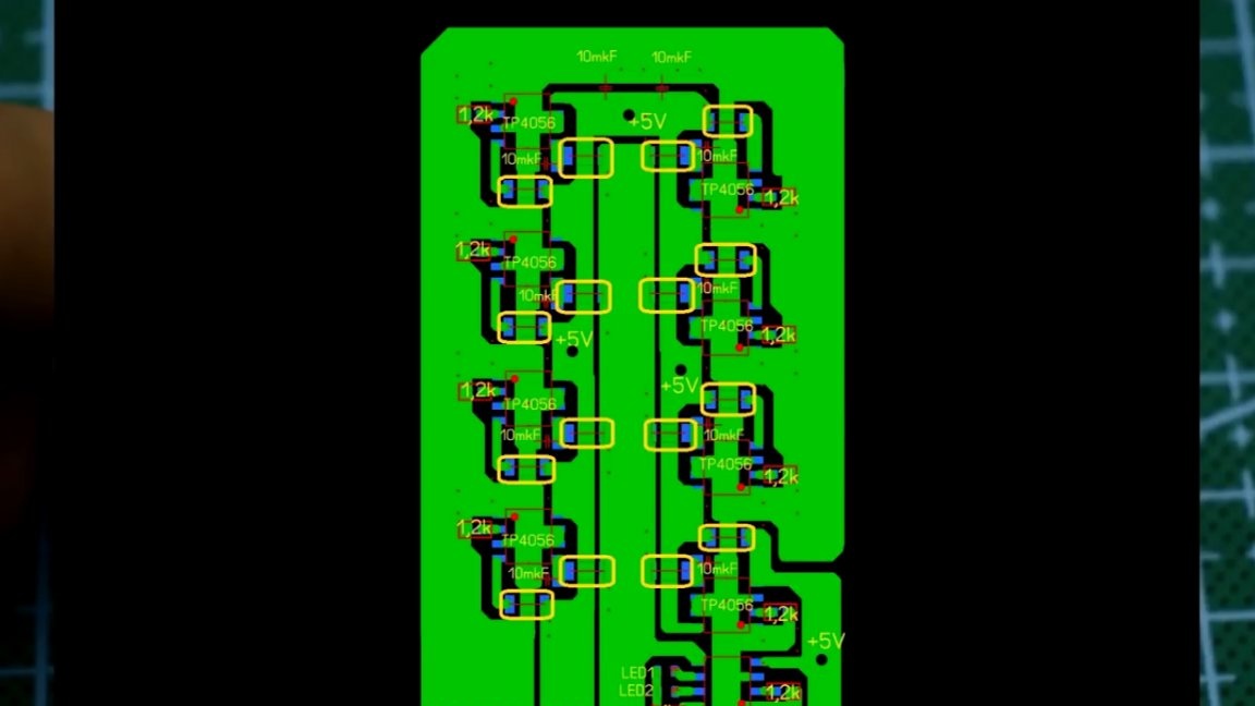
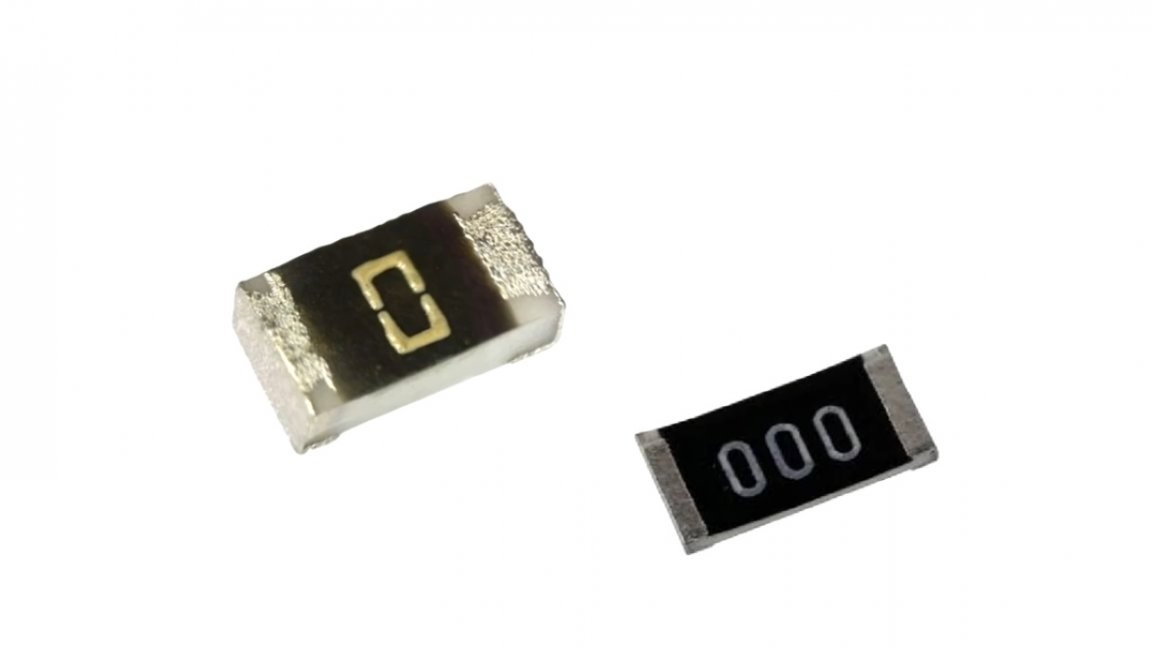
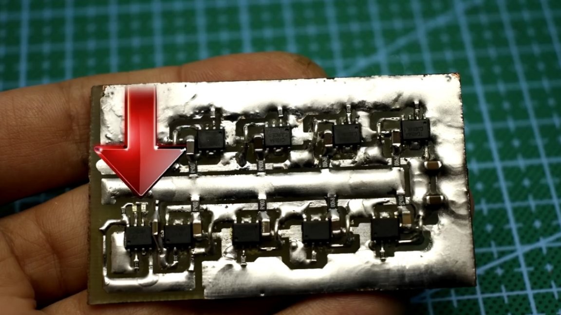
There are jumpers on the board, there are quite a lot of them. It is better to use smd jumpers (resistors with zero resistance), in this case several jumpers are replaced by resistors with a resistance of several hundred milliom, since the author did not have anything else at hand.
TP4056 microcircuits will heat up depending on the charge current and input voltage, they still work in linear mode, and on each microcircuit about 1W of power will go into heat if the input voltage is 5V. The total number of microcircuits is 9 and, accordingly, 9W of heat, this is a pretty strong heating.

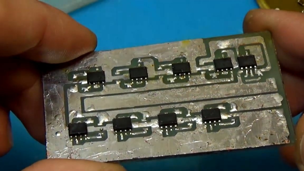
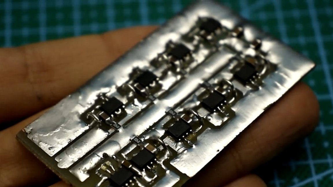
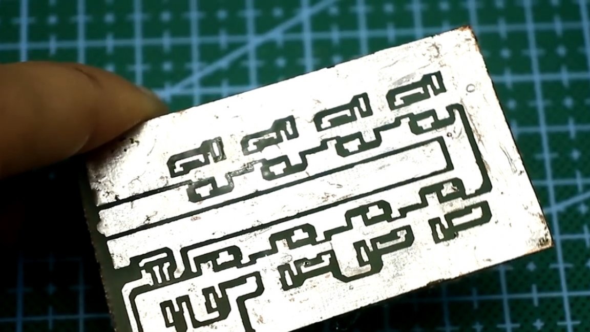
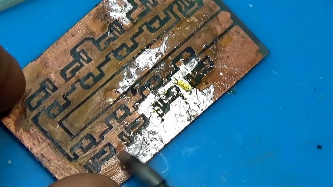
The chips themselves are cooled by massive tracks that are plentifully tinned. Although it would be much better to use a double-sided board where the copper coating on the second side would play the role of a radiator, but as they say - it will do so, later we will take thermal measurements and see how scary it is.
The author was very limited in time, otherwise (according to him) he would have ordered a two-sided board without jumpers and with good cooling at a factory in China.
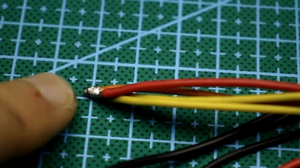
Due to the fact that the installation is one-way, there are several nuances. Currents of about 9-10A will flow along the power paths and in some places the paths are quite thin, so it is better to collect current in several places, then connect the wires in parallel.
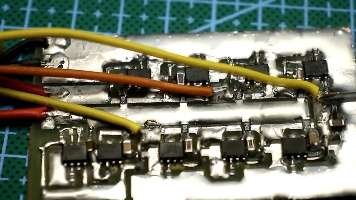
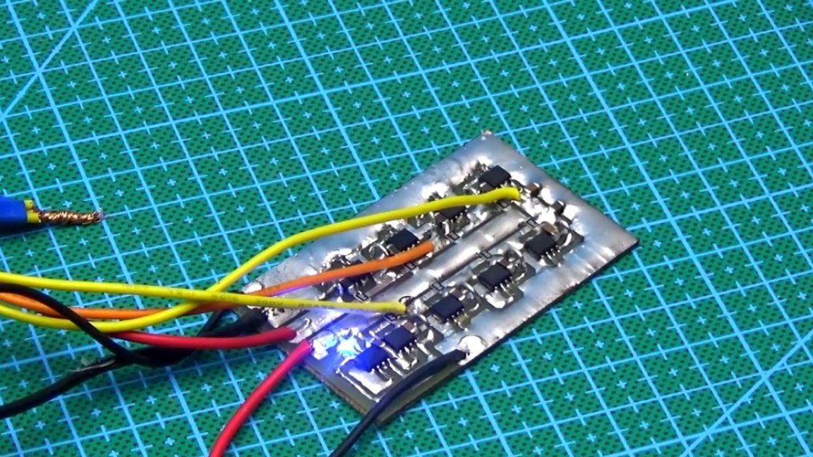
The first chip is the leading one, the rest are connected in parallel, purely to increase the total current.
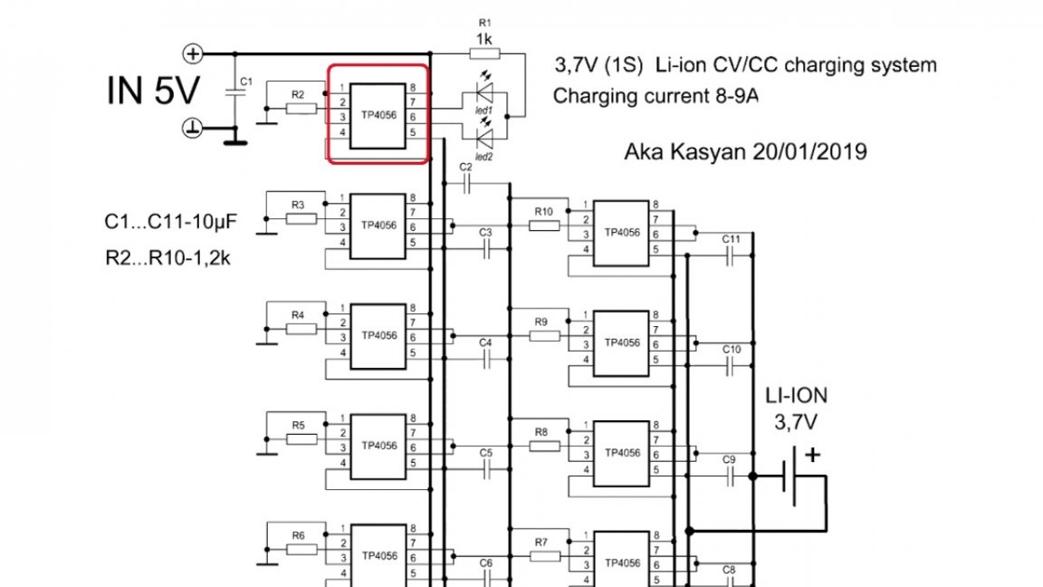
There are a couple of LEDs on the board. One glows during charging, the second - when the charge is over.
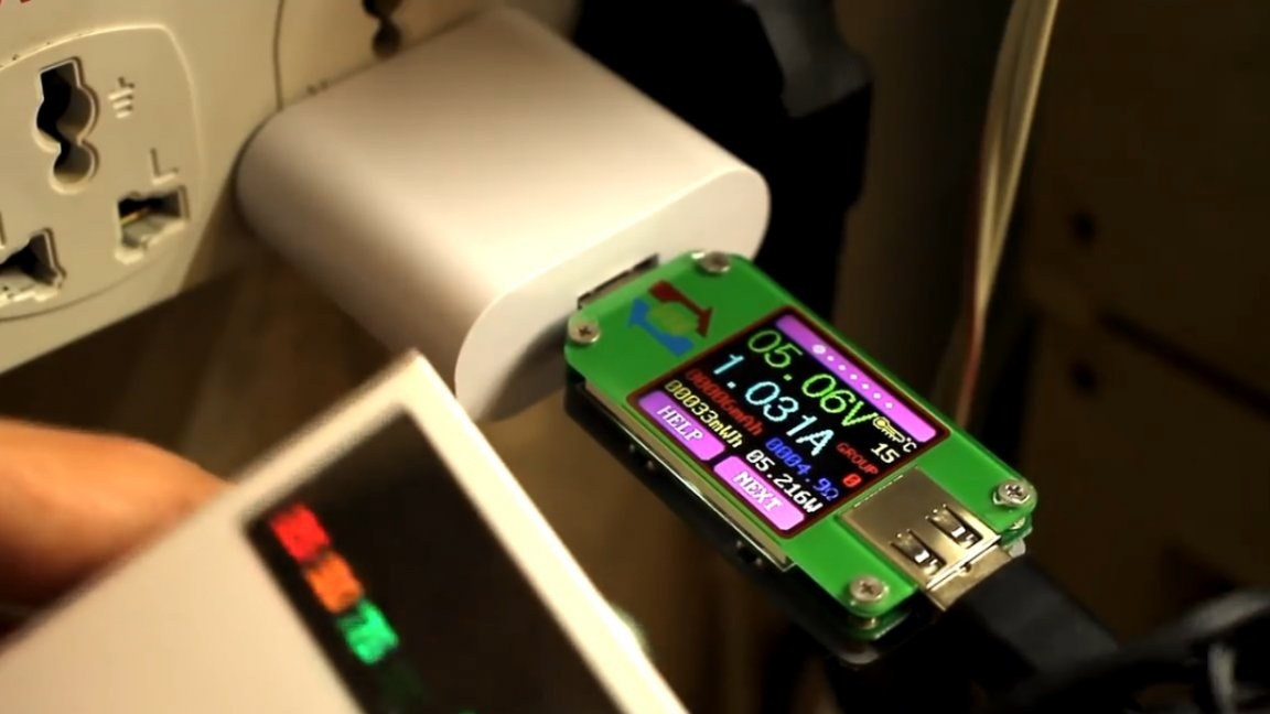
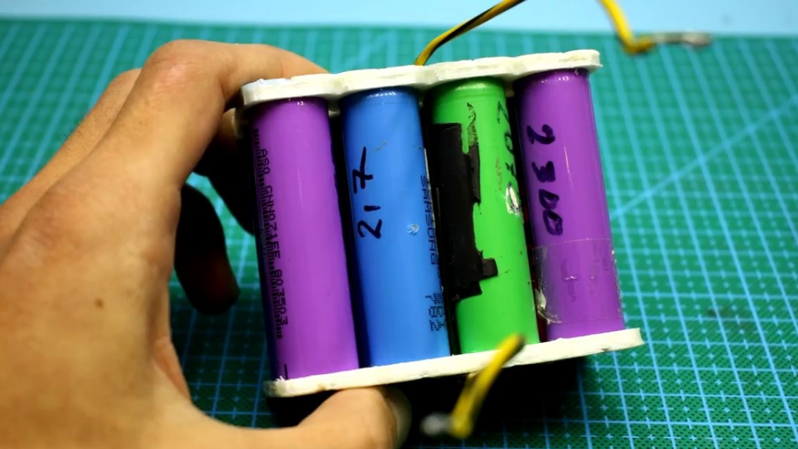
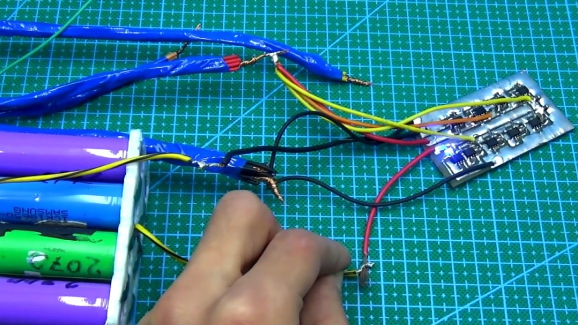
Well, now finally the test. As a test battery, we have an assembly of 18650 batteries with a total capacity of honest 18,000 mAh. The author previously discharged the battery.
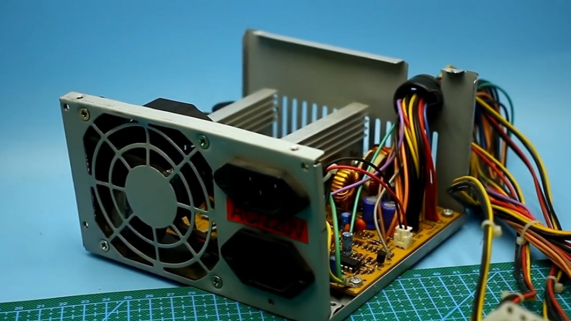
As a power source we will use a 5-volt line of a computer power supply.
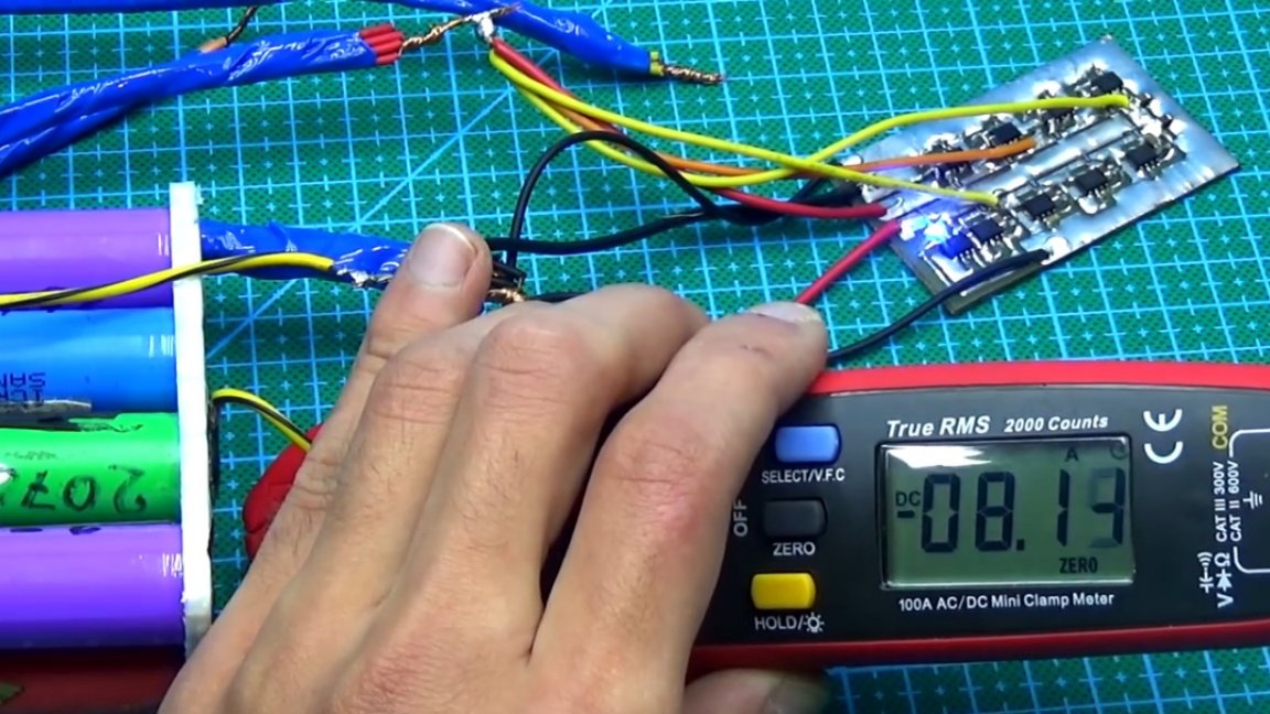
We connect. The process has started, the corresponding LED indicator lights up. The charge current in this case is about 8A and this, taking into account losses on the wires.
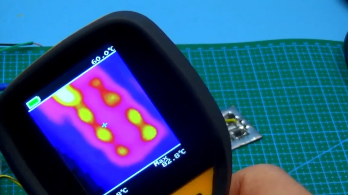
We are waiting for 20 minutes, then we take a thermal imager and we see that the board as a whole is quite hot, and the last 2 microcircuits that have not the best cooling are the most heated. The temperature on them reaches 83 degrees, but this is normal for TP4056 chips.
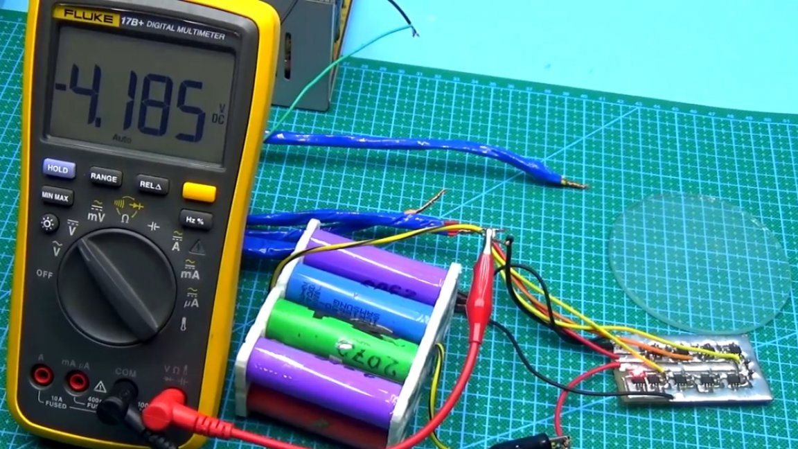
After about a couple of hours, the battery was fully charged, it is important to note that the current will fall as the charge, and, consequently, the heat generation on the charge board will decrease.
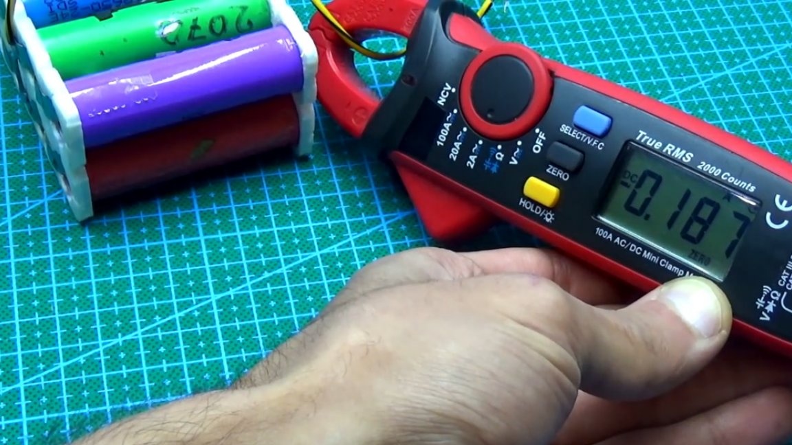
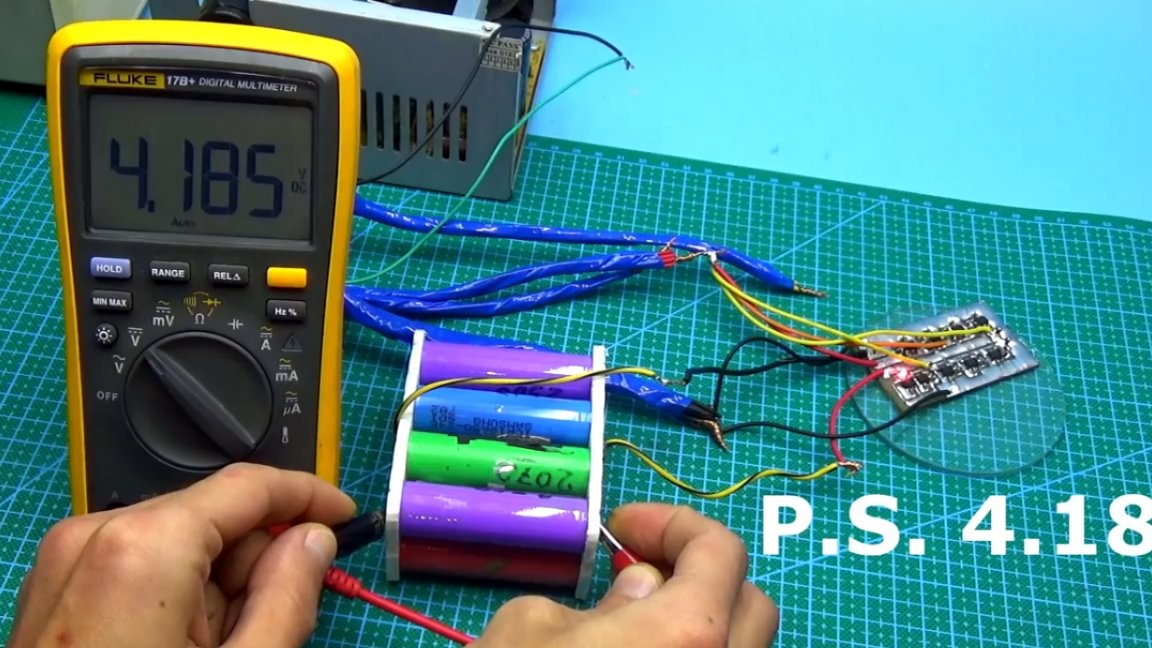
At the end of the process, the second indicator lights up, while the voltage on the batteries was 4.18V, which means that the assembled circuit is fully operational and copes with the tasks, so take the circuit into service, sometime it may come in handy.
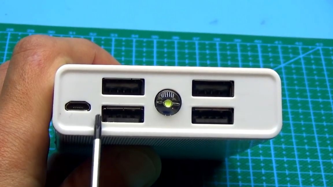
In the future, we will consider the protection scheme for such a powerful assembly, as well as assemble the entire powerbank and test it. It is also necessary to assemble the most important organ of the power bank - a powerful boost converter that will convert the voltage from lithium batteries to 5V, which are needed to charge portable electronics.
Well, this is the time to end. Thank you for attention. See you soon!
Video: