Almost all of the iron was purchased at metal acceptance.
A bed from a profile pipe 50x50 was purchased as a whole, it was not digested, it came up and so.
The crusher body is a piece of pipe with a diameter of 55 cm and a width of 50 cm.
The sides of the casing from a sheet of 6 mm and the upper parts of the sidewalls are removable so that you can clean the crusher and change the knives. The shaft for the crusher is machined from a 35mm hexagon and 35x steel.
A drum from an old winch was put on the shaft. On the drum there are studs with a diameter of 14 mm, the same very strong steel. Knives (or hammers) are cut out by a grinder from plowshares (steel 65g).
Further to the crusher body (to the pipe), an inlet hopper of 300x300 mm in size was welded and an exit window of the same size was placed below. Then they put the engine connecting it to the crusher shaft through a rubber coupling.
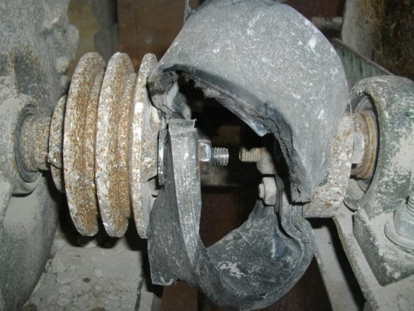
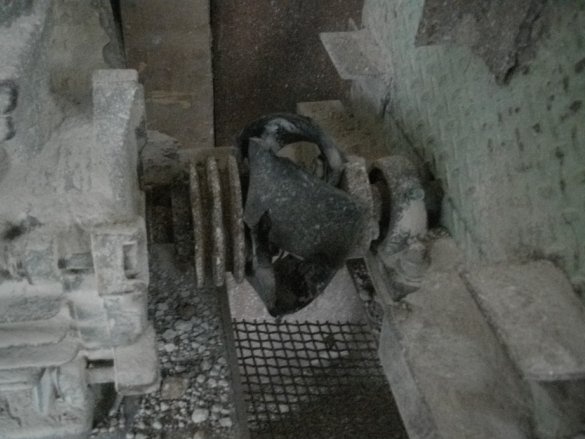
I’ll say separately about the engine: the first one was 3 kW at 1,500 rpm (it was fired a couple of times), the second was 4 kW and 960 rpm. Well, the second one suits me more since it gives out a larger fraction, that is less dust. The rubber coupling is made of two metal washers with 10-12 mm holes (I have three on the washer, someone makes four), one washer is put on the motor shaft and the other on the crusher shaft and connected to each other by pieces of conveyor belt, pressed to the washers with bolts. A rubber coupling is needed in order to: 1) there is no alignment of the engine and shaft) 2) vibration from the crusher shaft is not transmitted to the motor shaft, 3) it is easily repaired, 4) a wheelbarrow easily becomes under the crusher.


