


In this homemade The author proposes to create a miniature lathe using commonly available equipment and tools. It is proposed to use a DC motor from an old washing machine as the engine for the machine. You will also need a few acrylic sheets and a bunch of aluminum tubes.
Let's get started ...
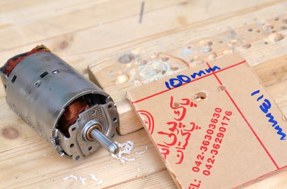
Step 1: Removing the engine
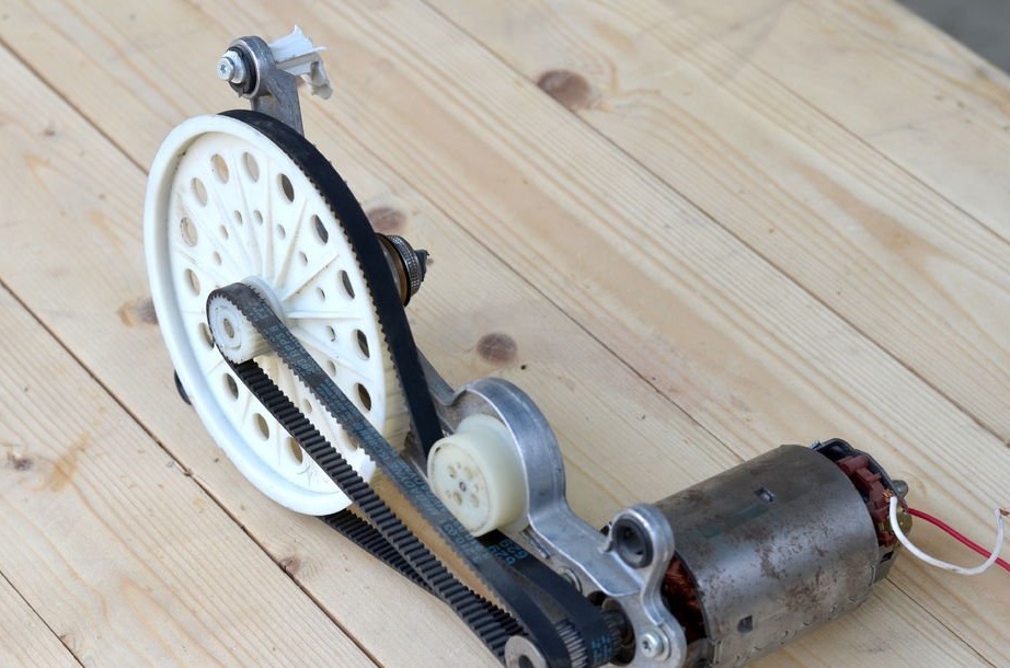
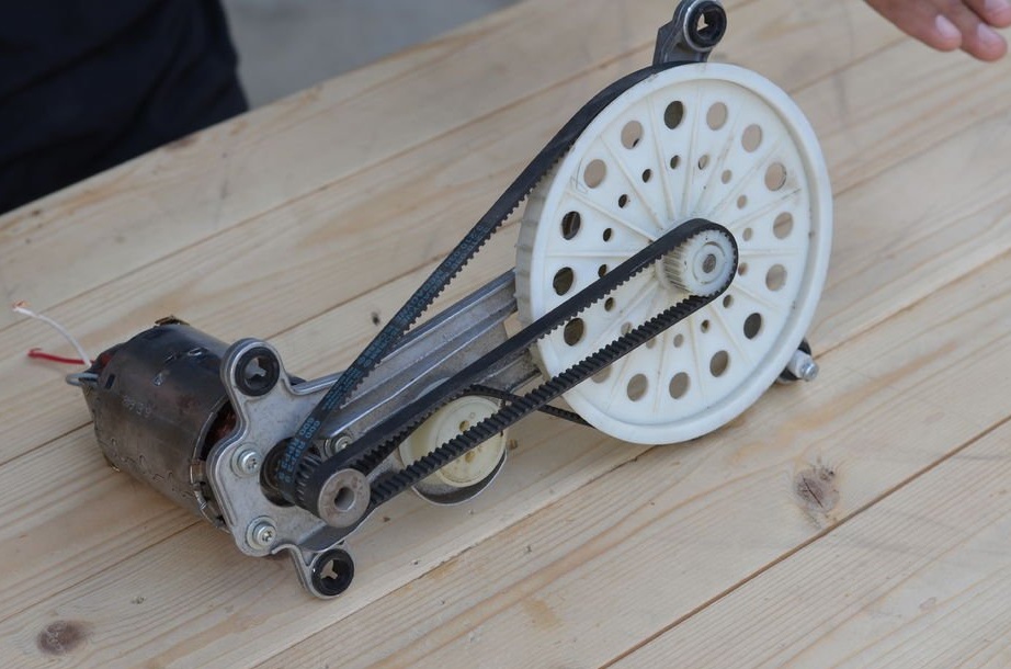
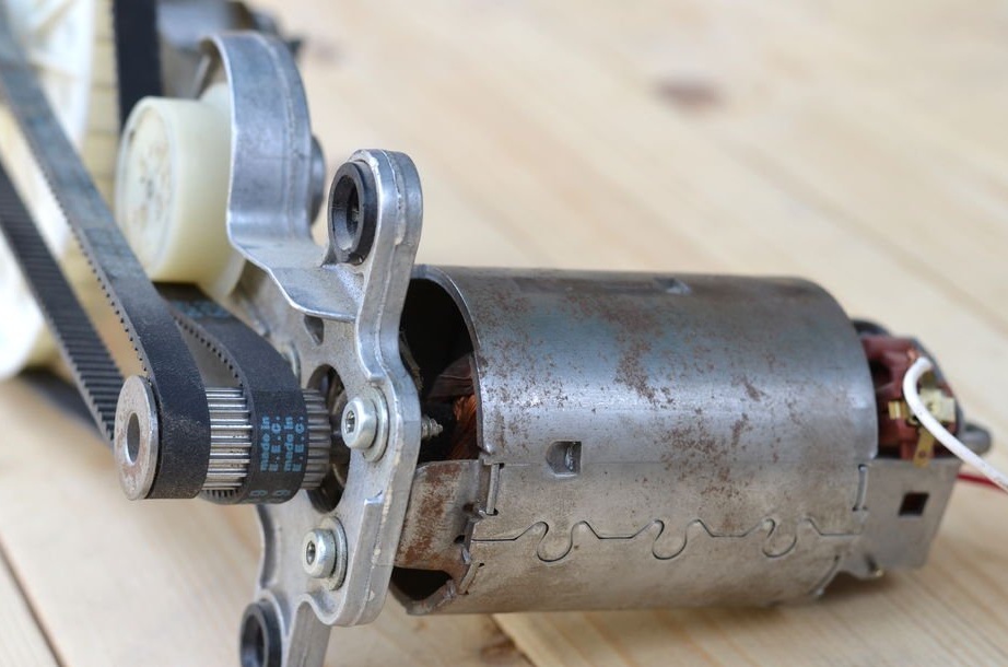
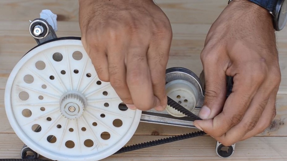
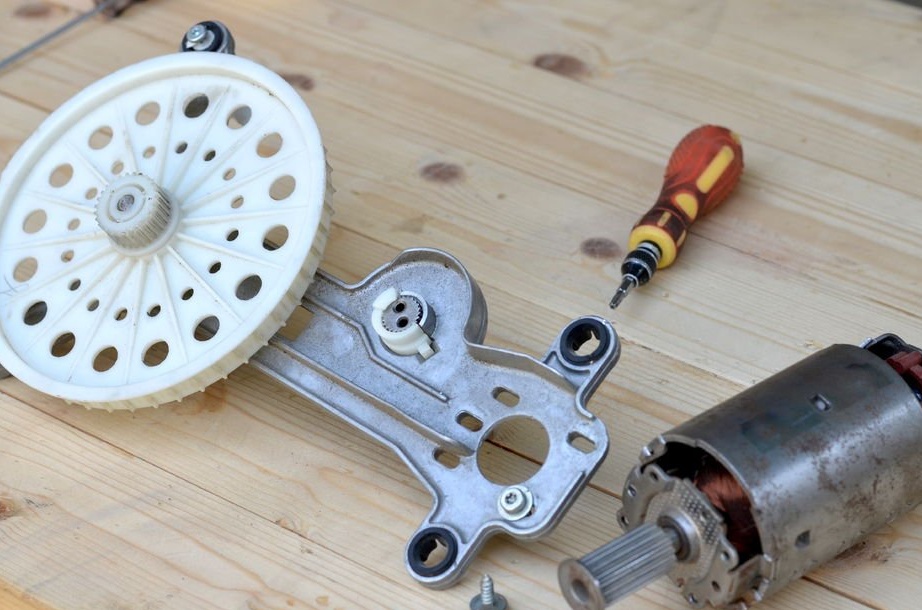
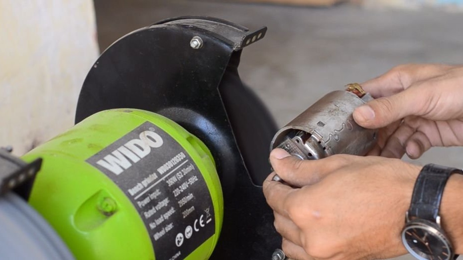
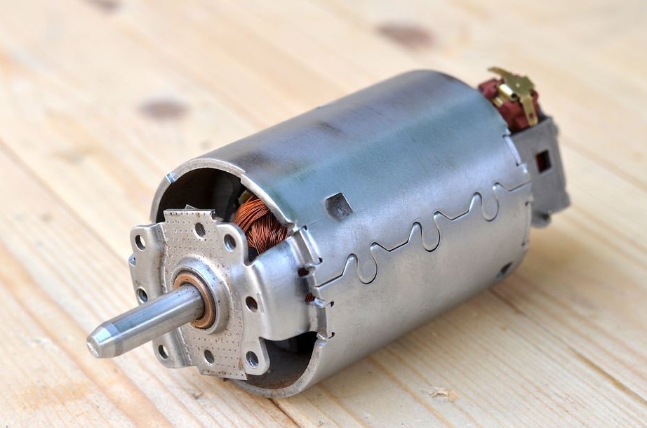
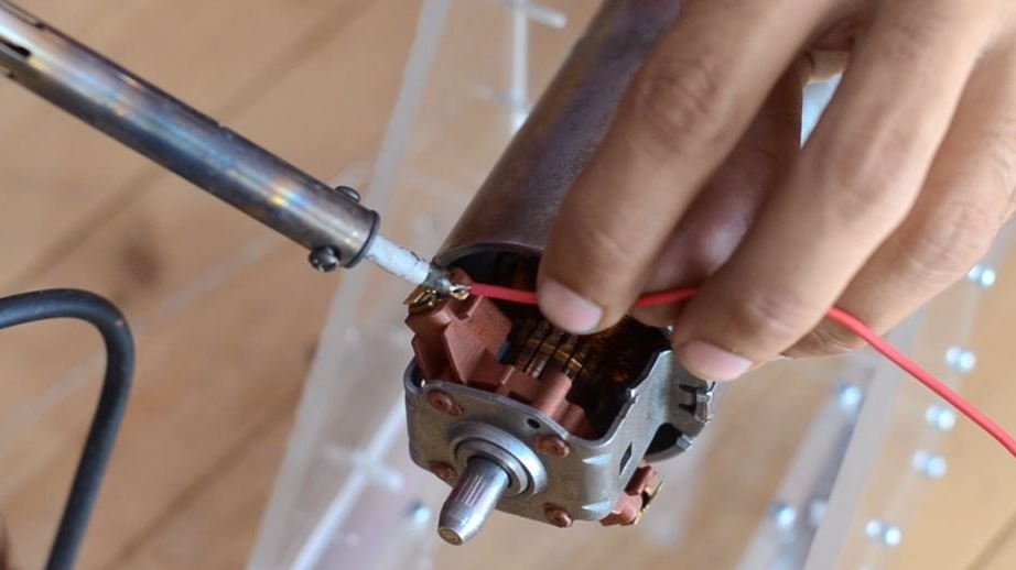
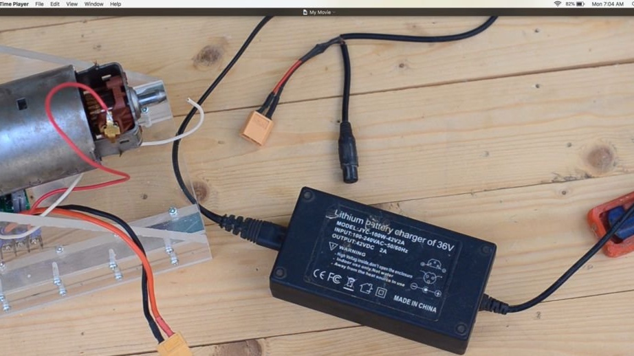
To begin with, we remove the fasteners from the old DC motor. This engine produces good torque. This has been tested with a 42-volt DC adapter. The engine runs quietly, so we remove the engine from the assembly and remove the pulley, and then remove the rust from the engine housing using a table grinder.
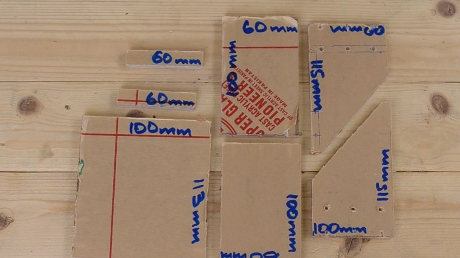
Step 2: Making Machine Elements
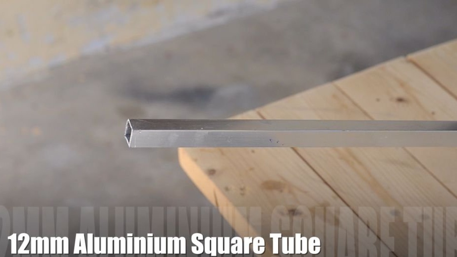
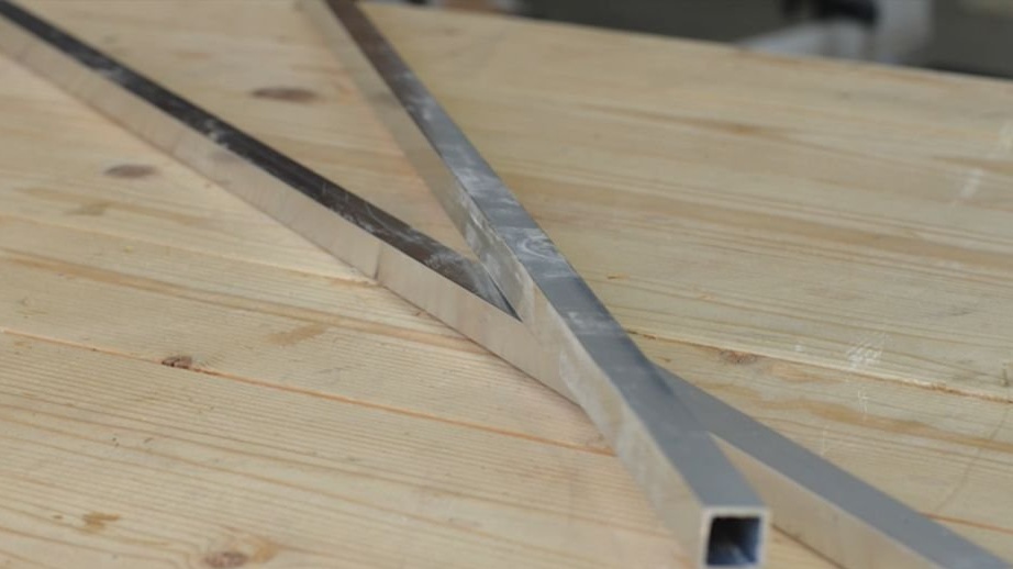
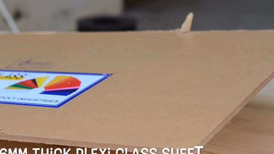
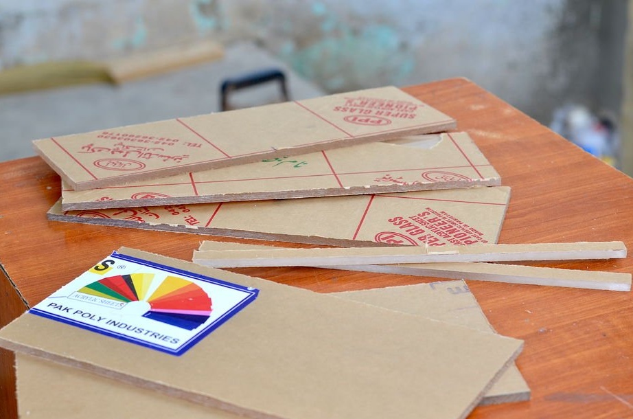
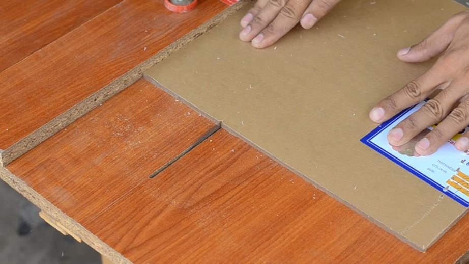
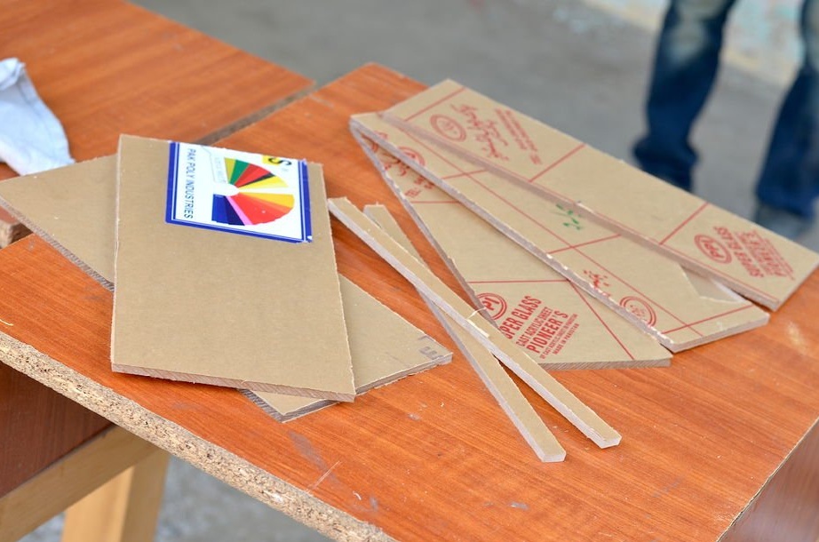
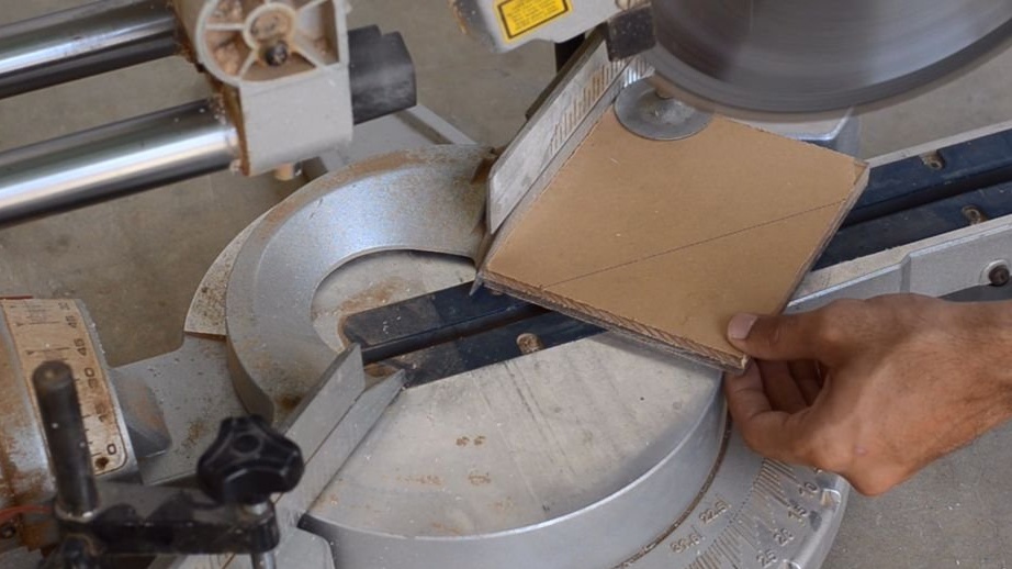
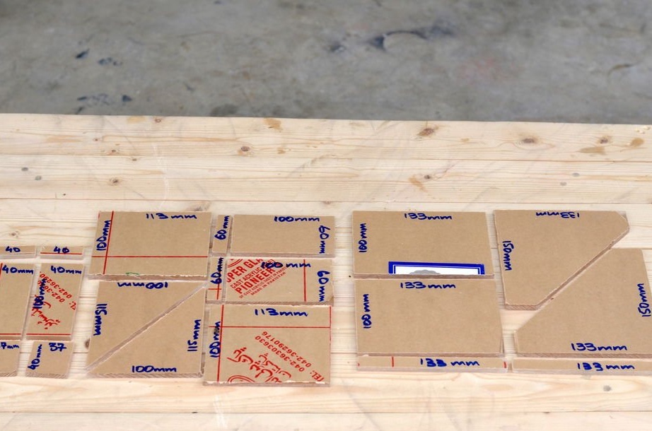
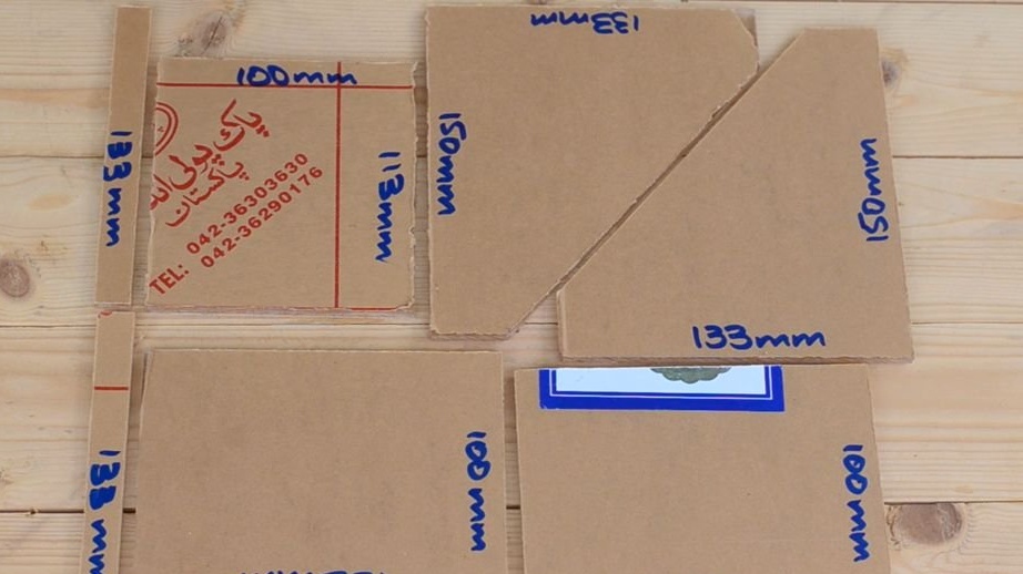
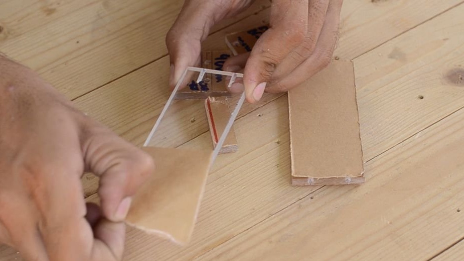
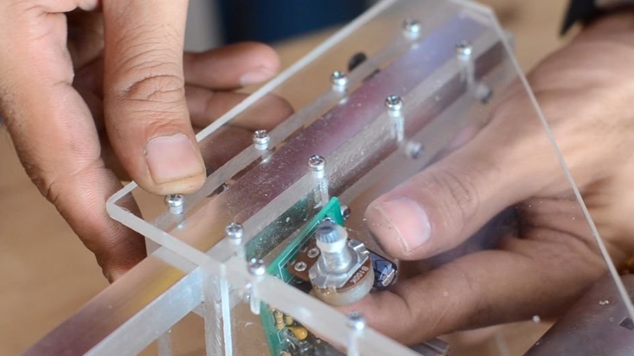
The guiding rails of the lathe are made of square aluminum pipe, 12 mm wide and 60 cm long. All body parts for this lathe are made of 6 mm thick plexiglass sheet. All parts are cut with a miter saw and a home-made table saw.
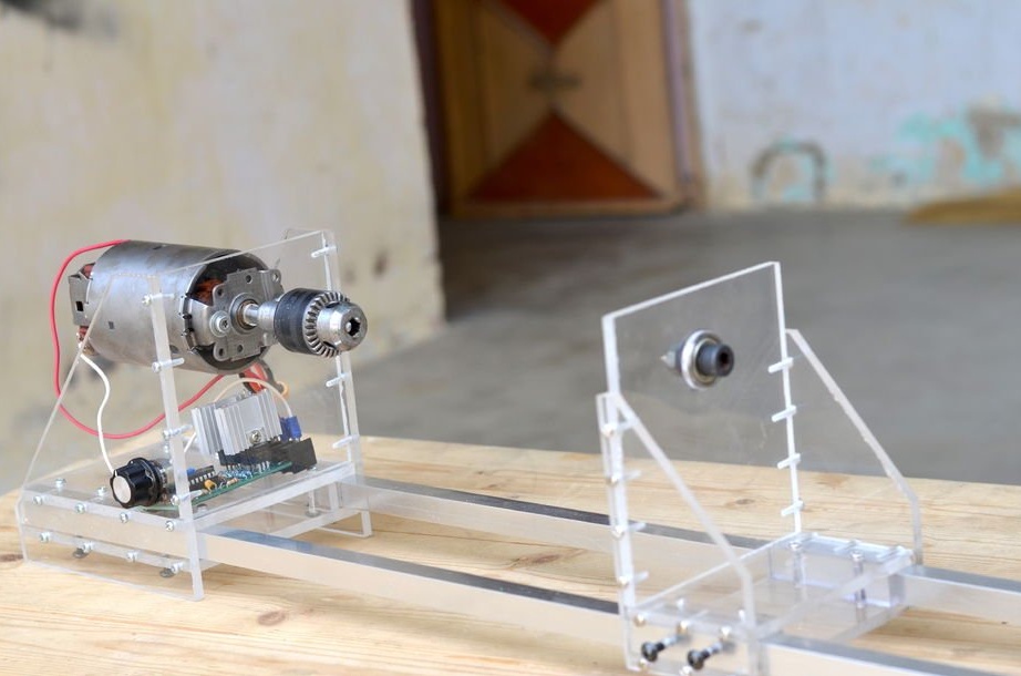
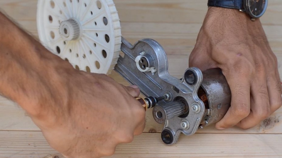
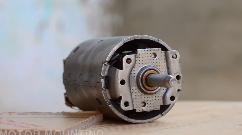
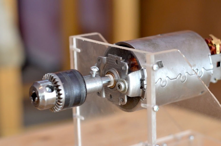
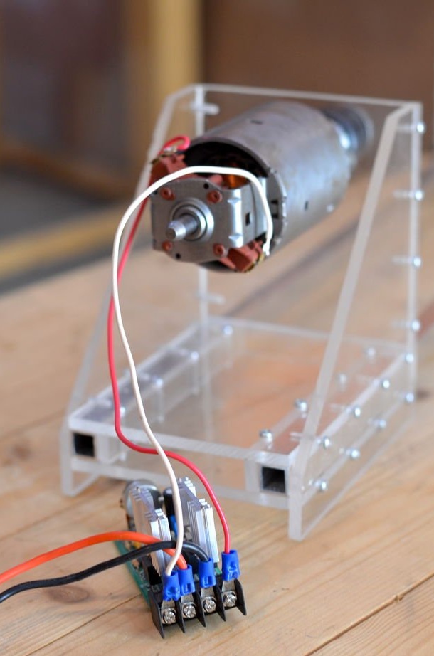
Step 3: Assembling the engine mount
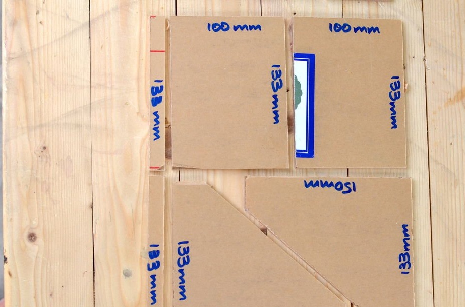
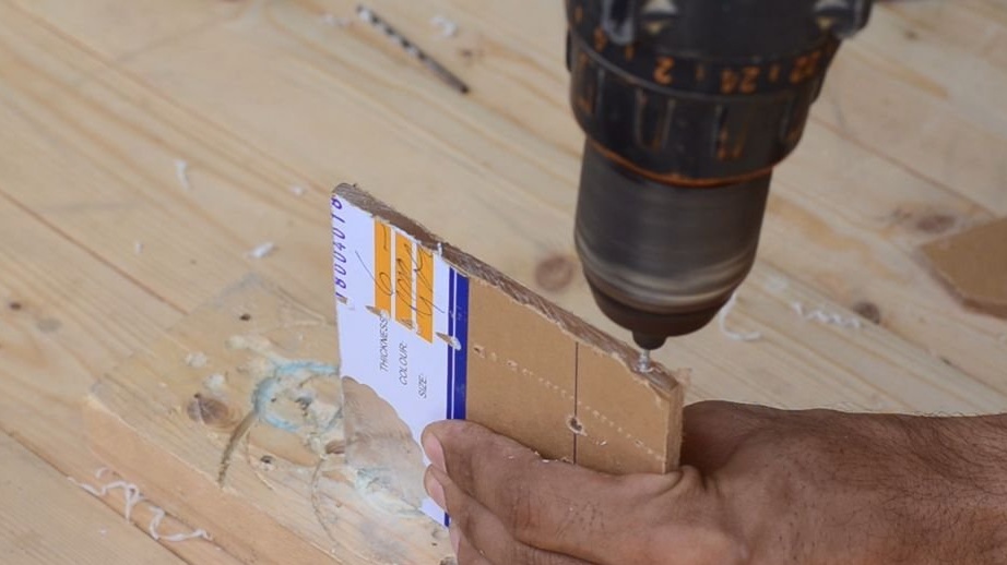
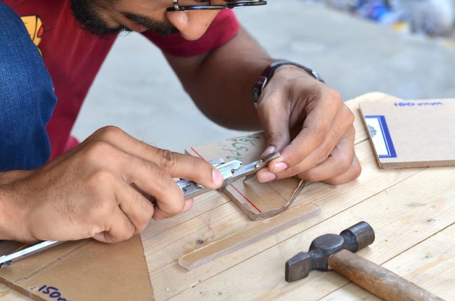
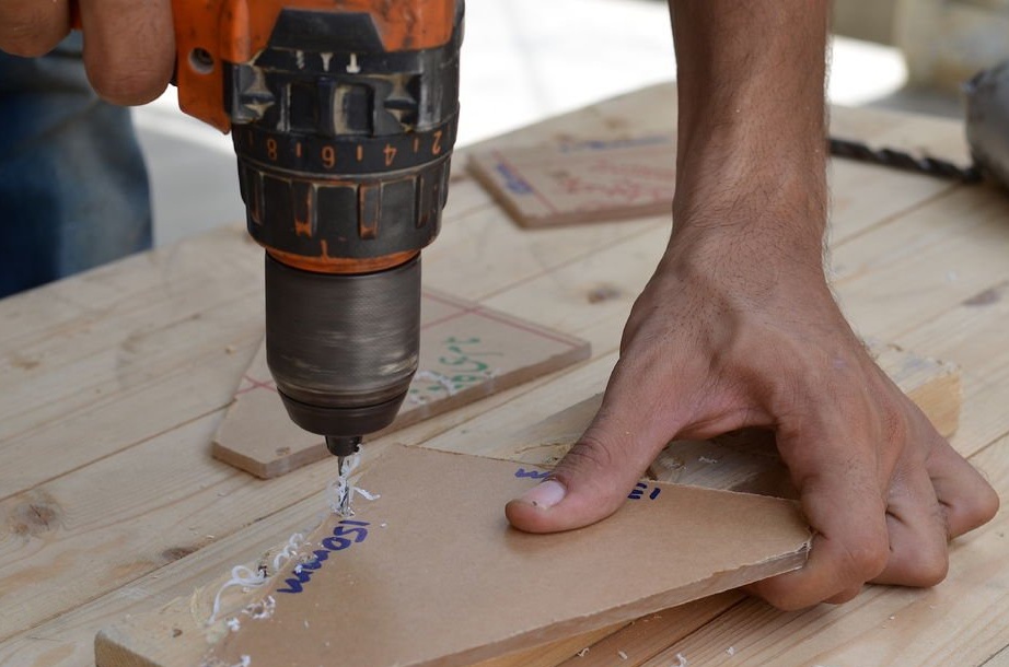
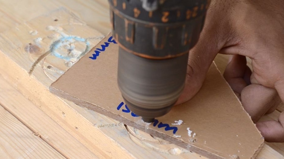
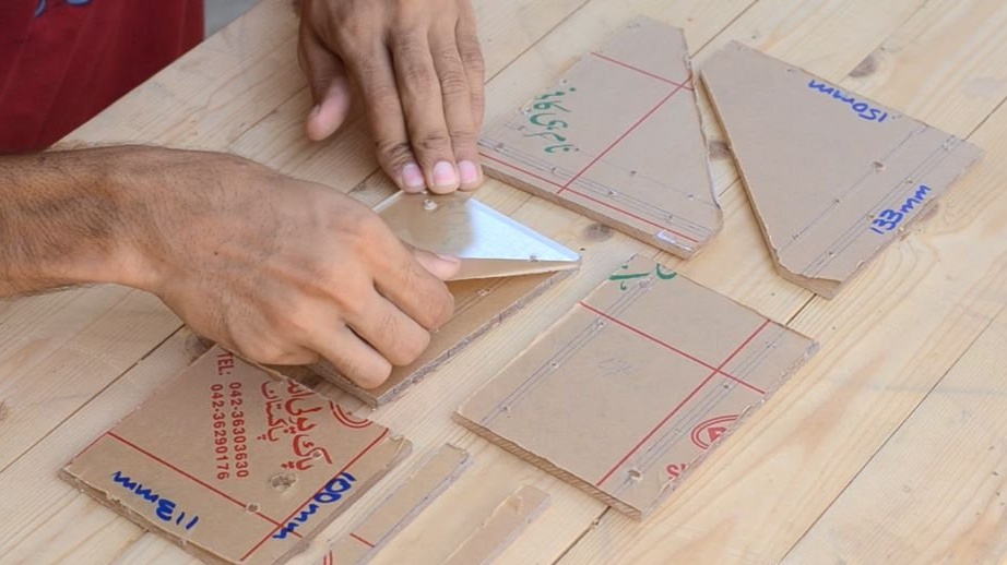
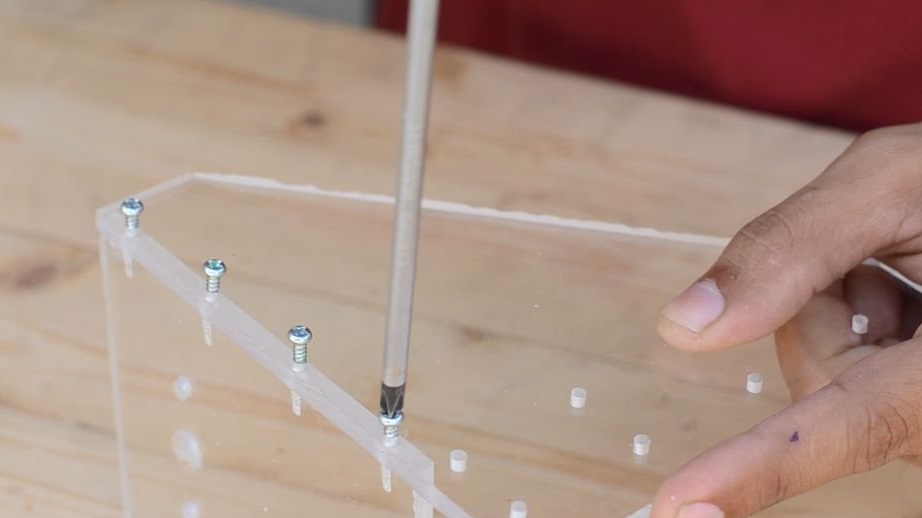
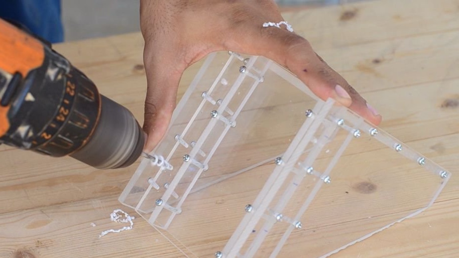
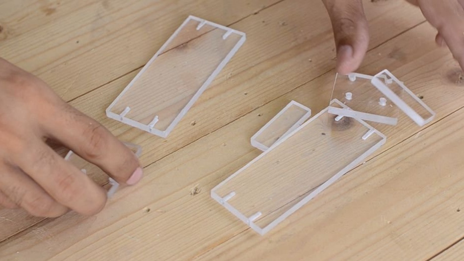
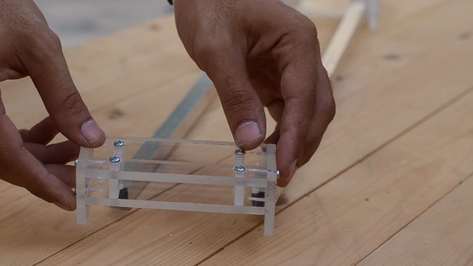
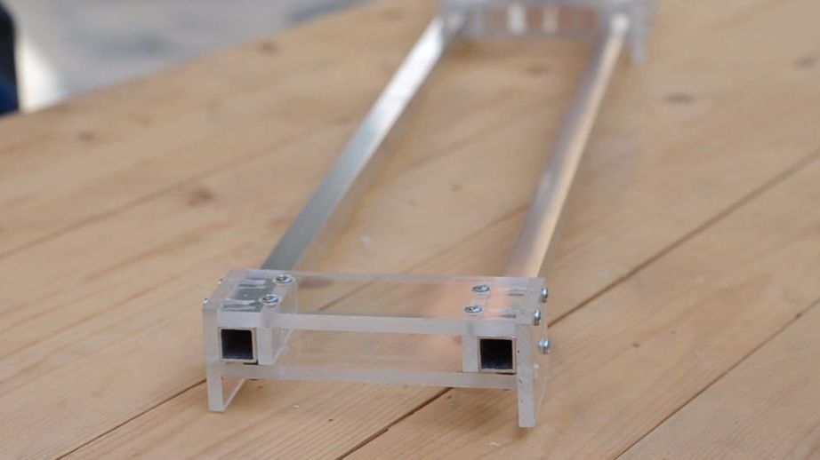

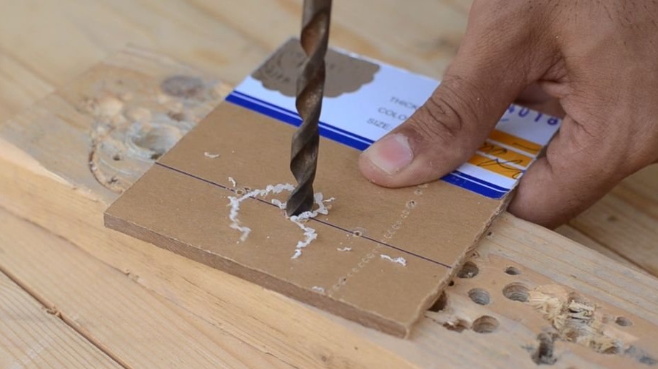
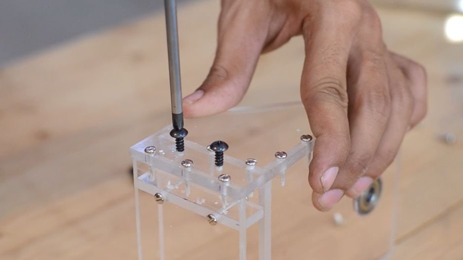
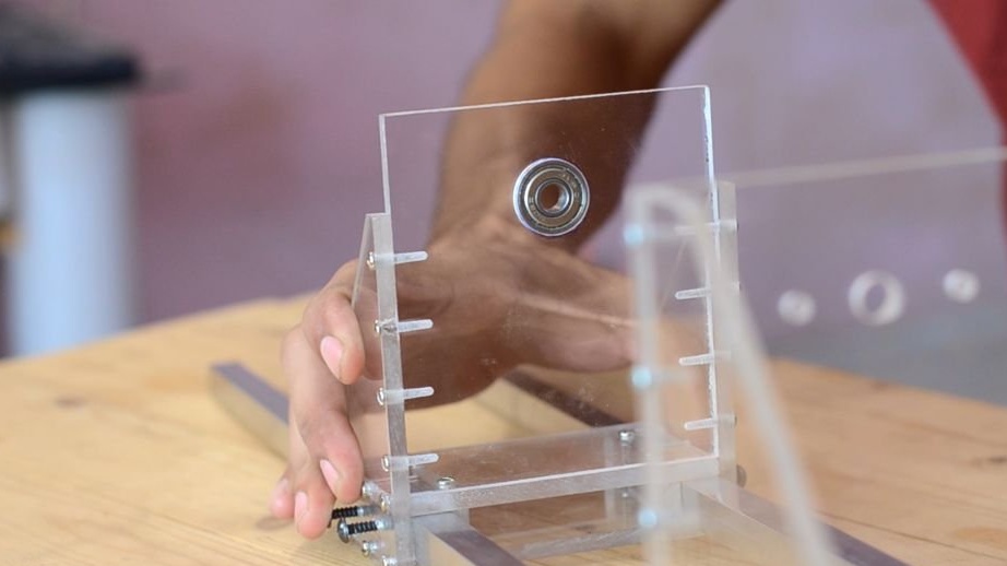
Having cut out all the parts necessary for the construction, the engine mount is assembled. To make the entire structure as strong as possible, a threaded screw is used for assembly, instead of glue. To do this, drill holes in each part and connect with a screw 60 mm long.
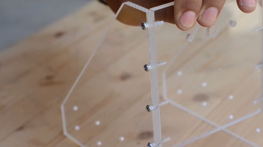
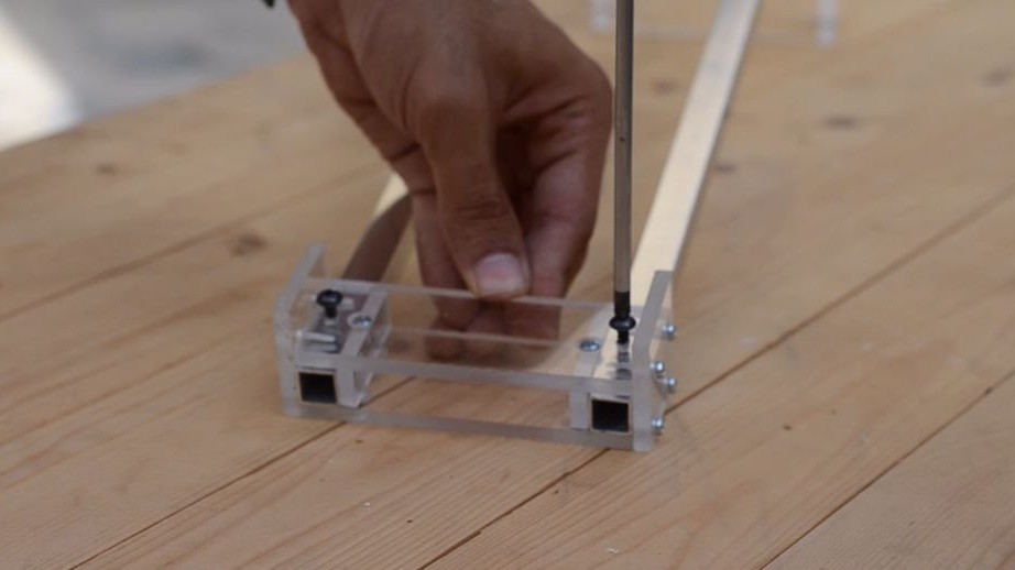
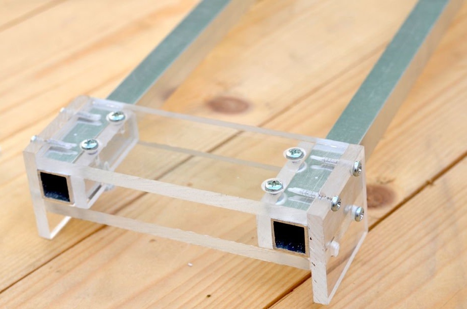
To prevent the engine mounting from sliding along the aluminum rails, four threaded screws were added at the bottom of the plate, which are attached to the rails when tightened.
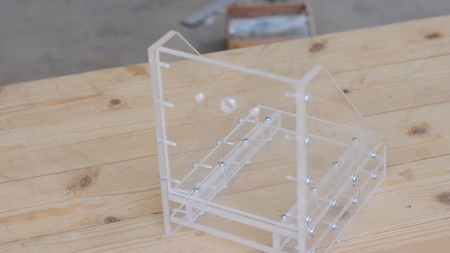
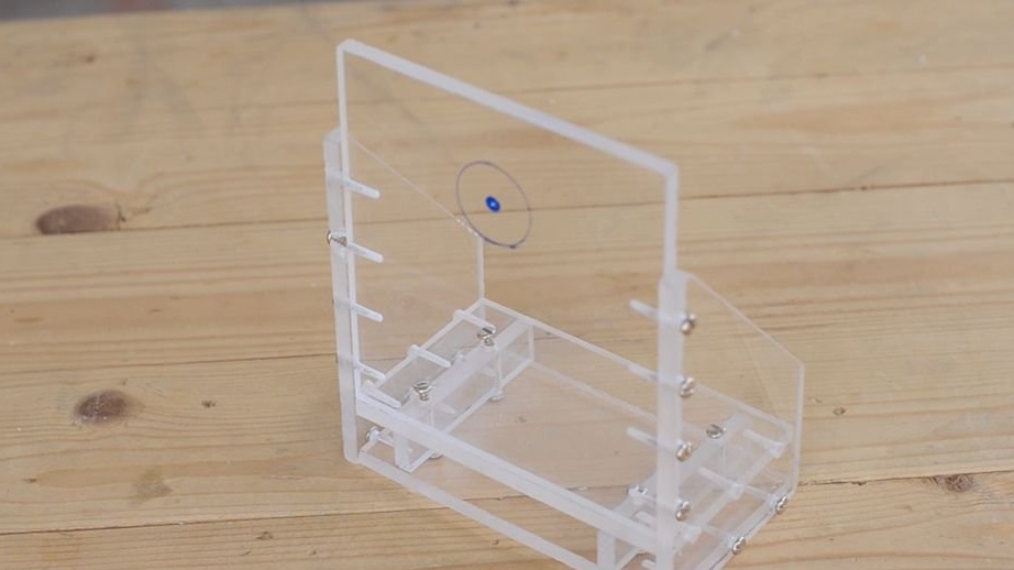
The same approach is used to manufacture another part.
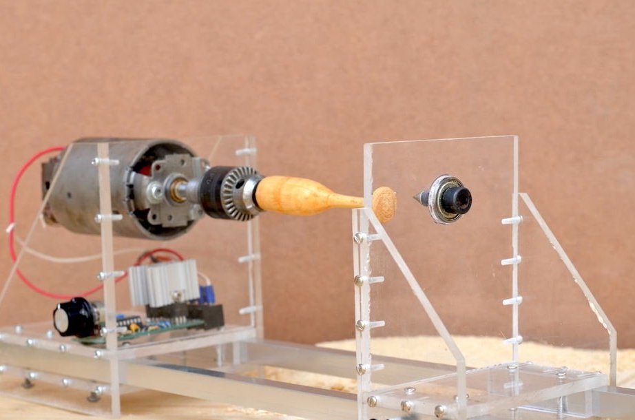
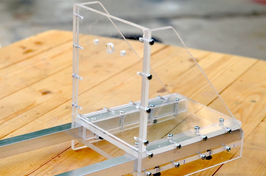
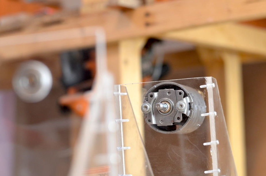
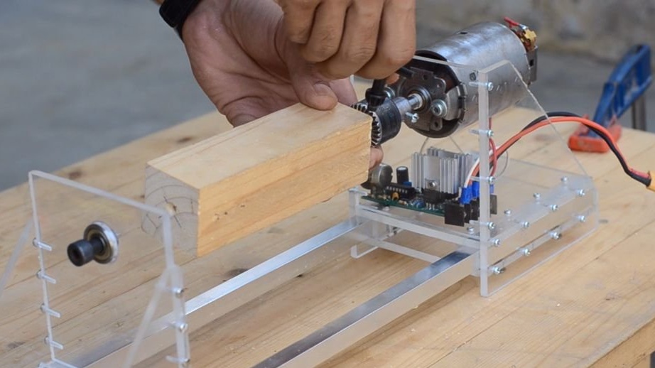
Step 4: Attaching the Drill Chuck
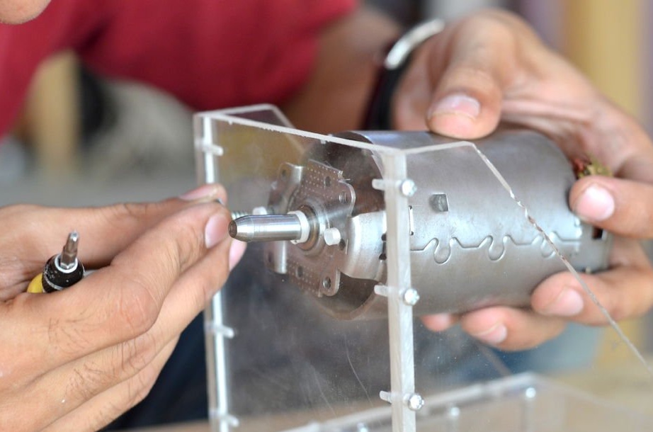
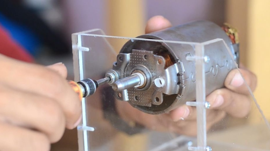
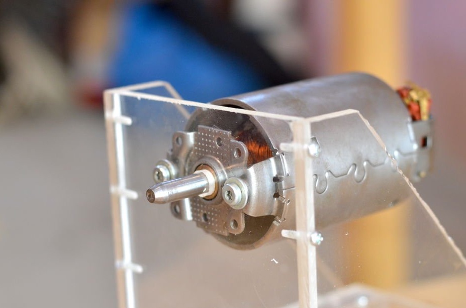
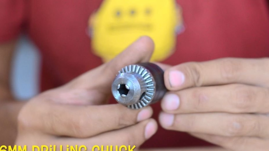
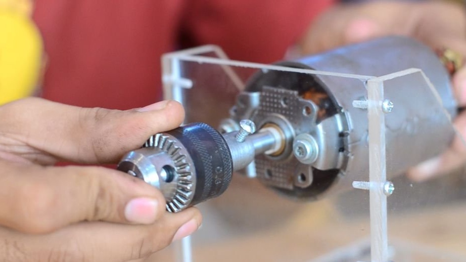
After the manufacture of the structure, the engine is mounted using two 5mm threaded screws. A 6mm drill chuck is attached to the motor shaft, which will fix the rotating part.
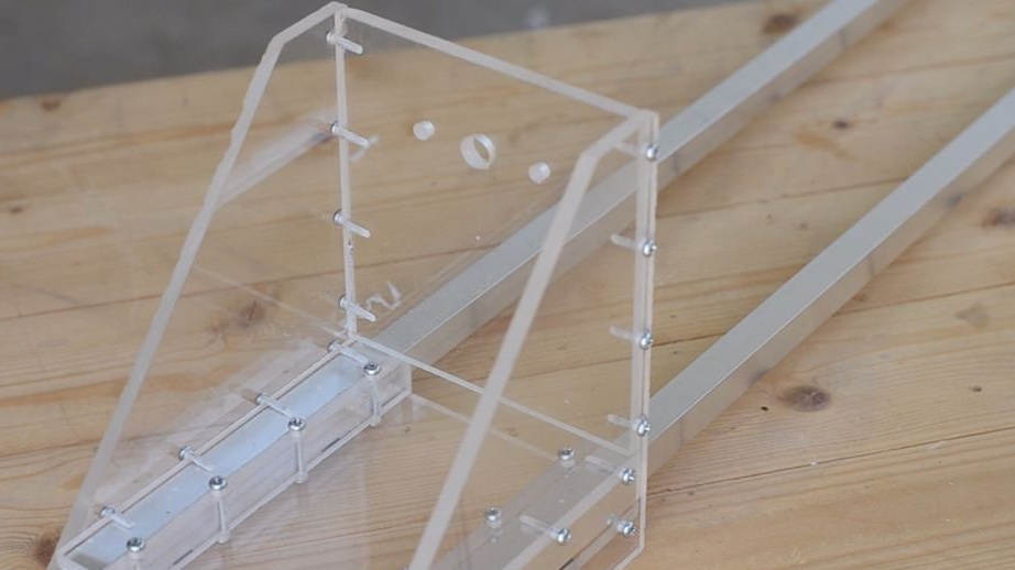
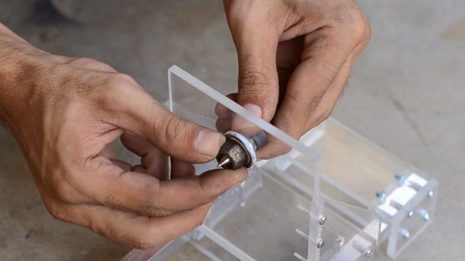
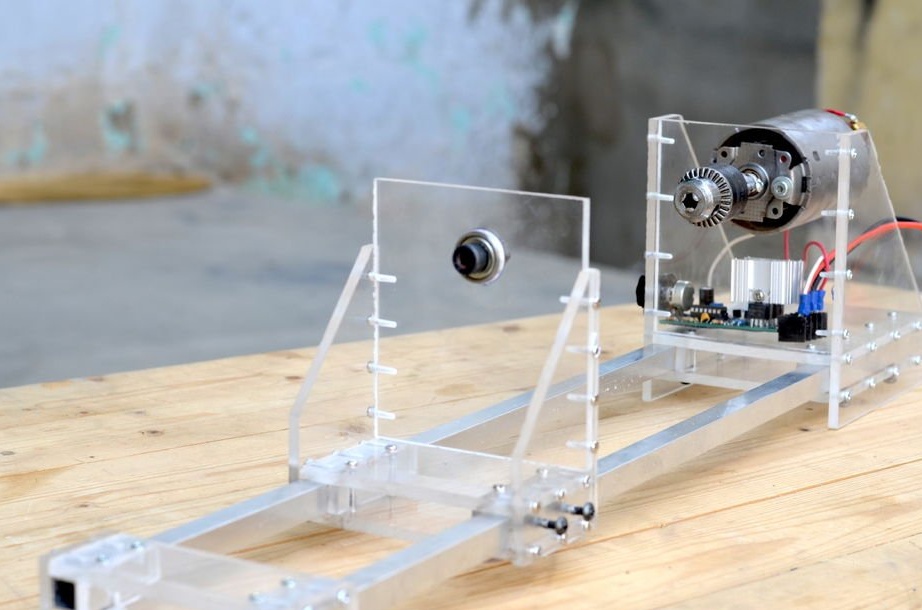
Step 5: Assembling the Bearing Holder
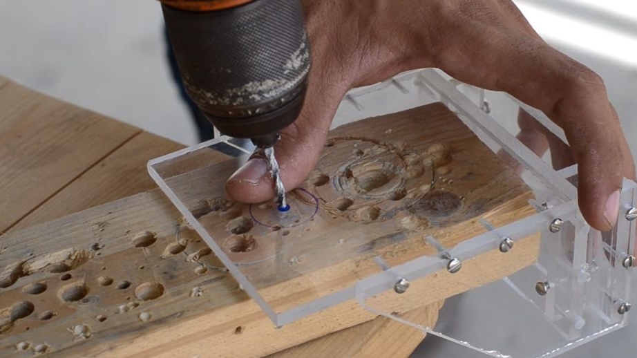
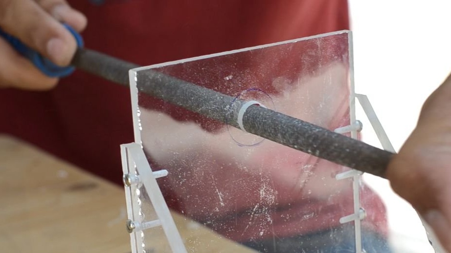
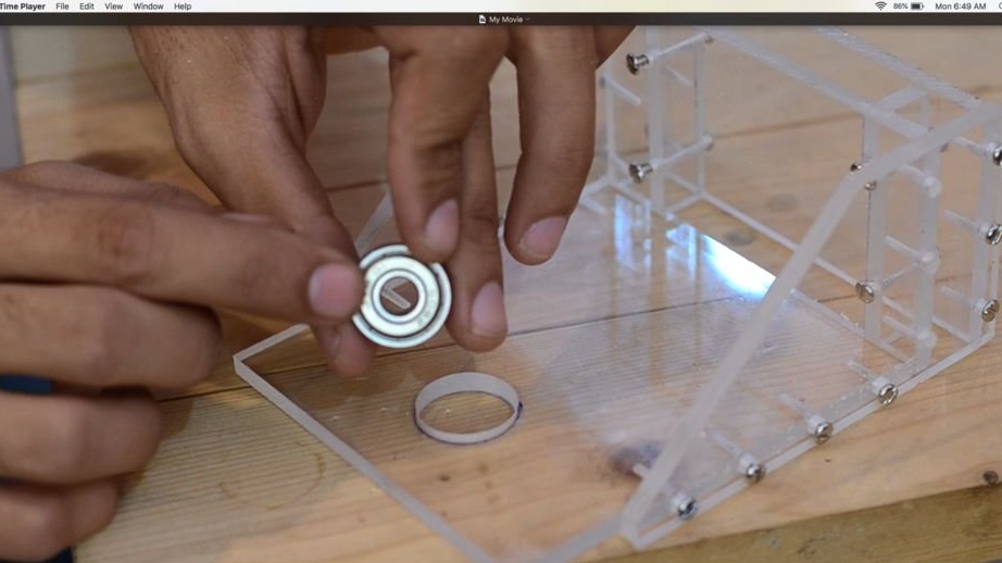
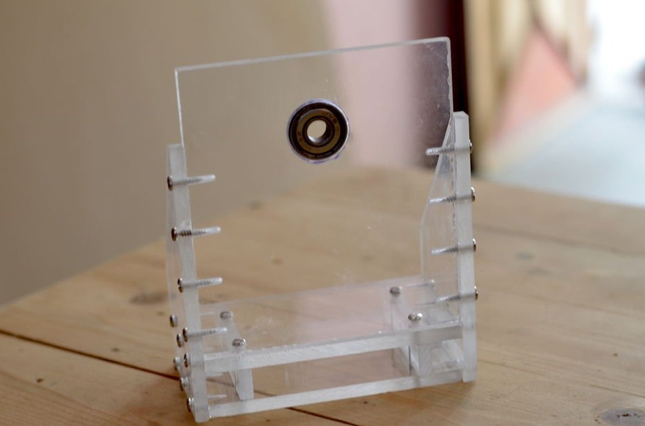
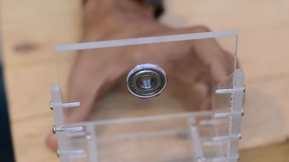
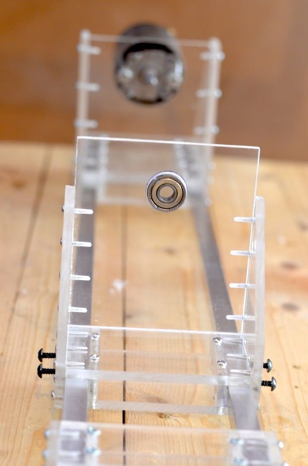
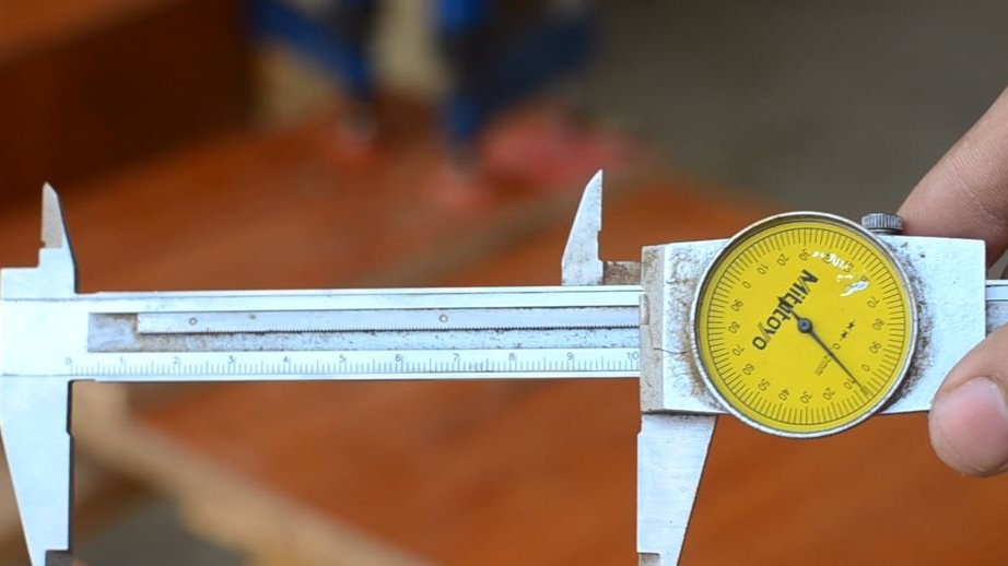
A bearing is mounted on a stand opposite the engine.To do this, a hole is drilled and, with the help of a round file, is increased to the desired size. The outer dimension of the bearing is 32 mm, the inner is 8 mm. Later, a shaft with a diameter of 8 mm will be installed inside the bearing. In the finished hole, the bearing is inserted in a tight, without the use of glue. The bearing holder has free play along the guide rail.
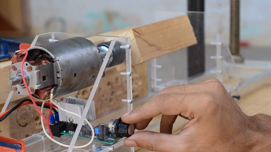
Step 6: Engine Speed Controller
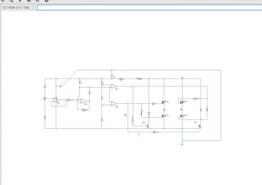
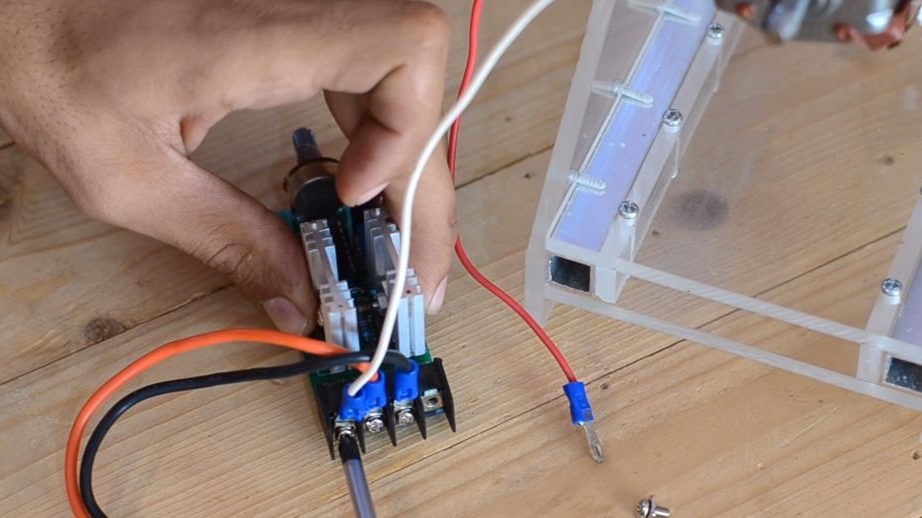
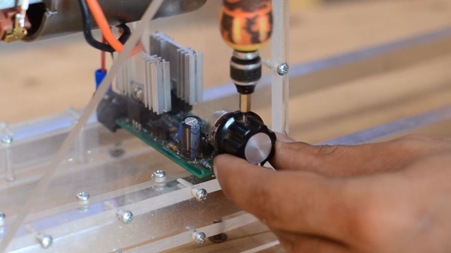
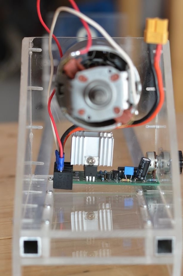
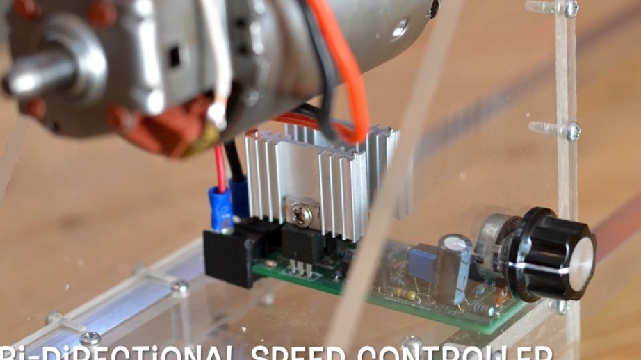
To control the lathe, you must assemble a bi-directional speed controller, which allows you to control the speed and direction of rotation using only one handle.
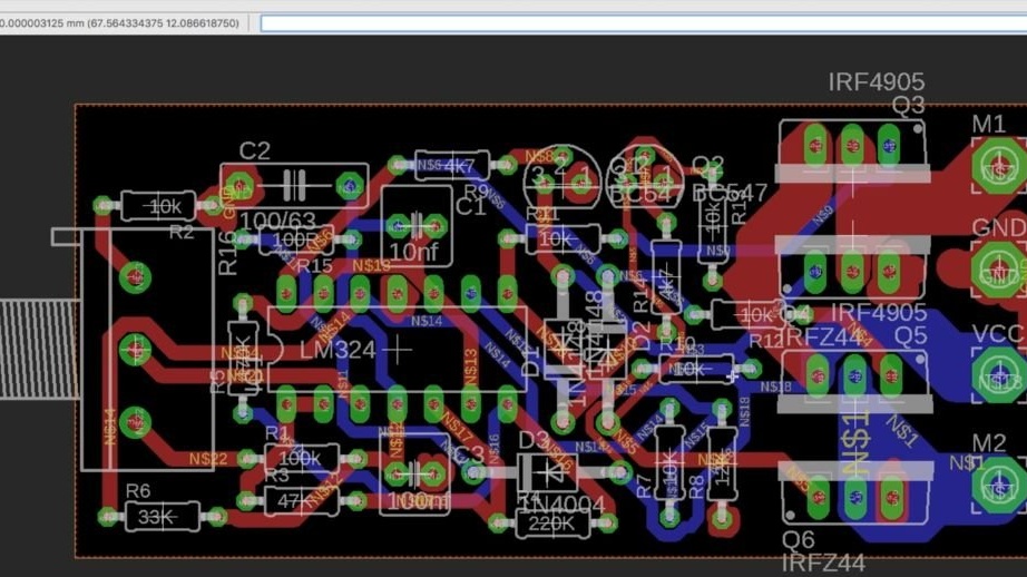
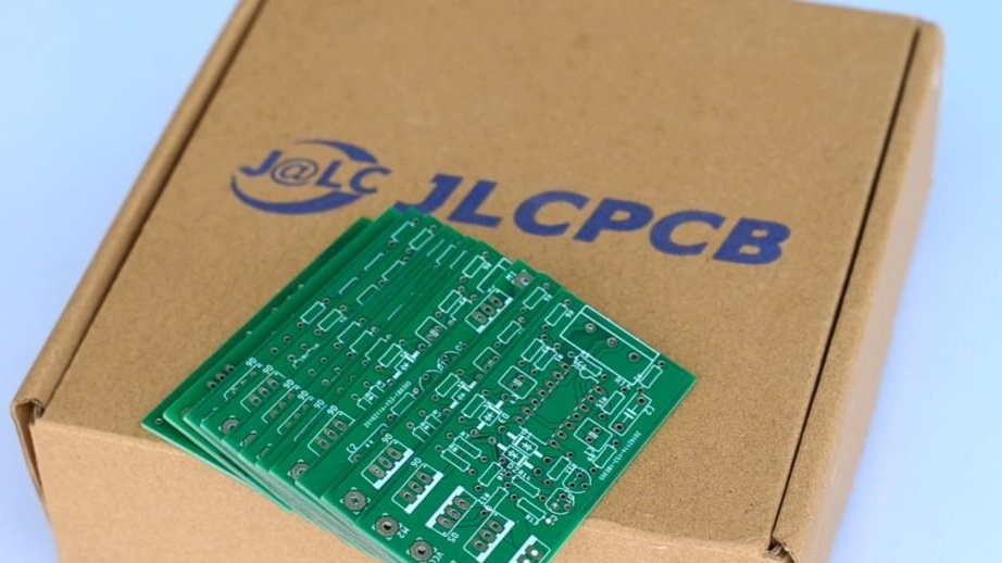
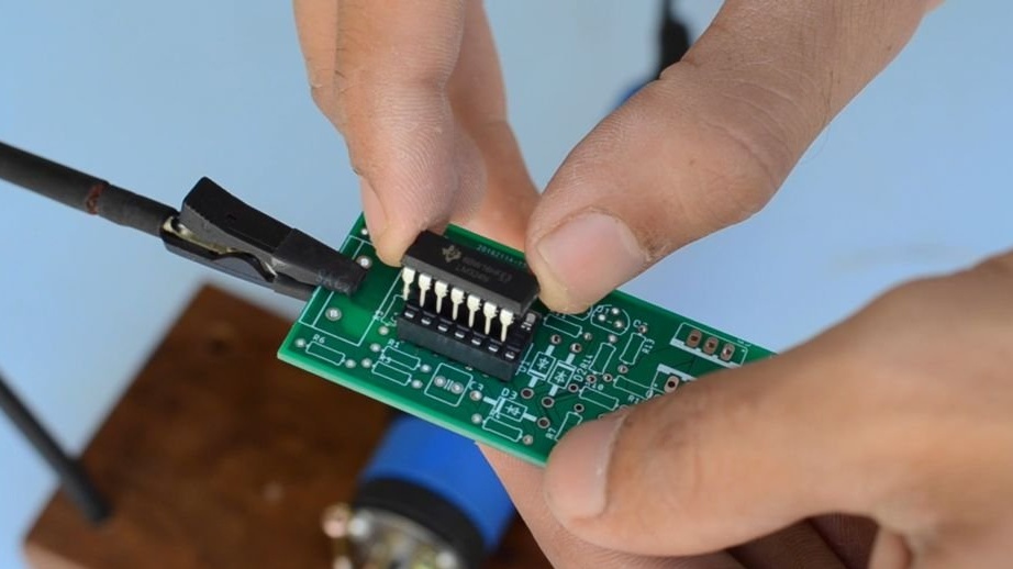
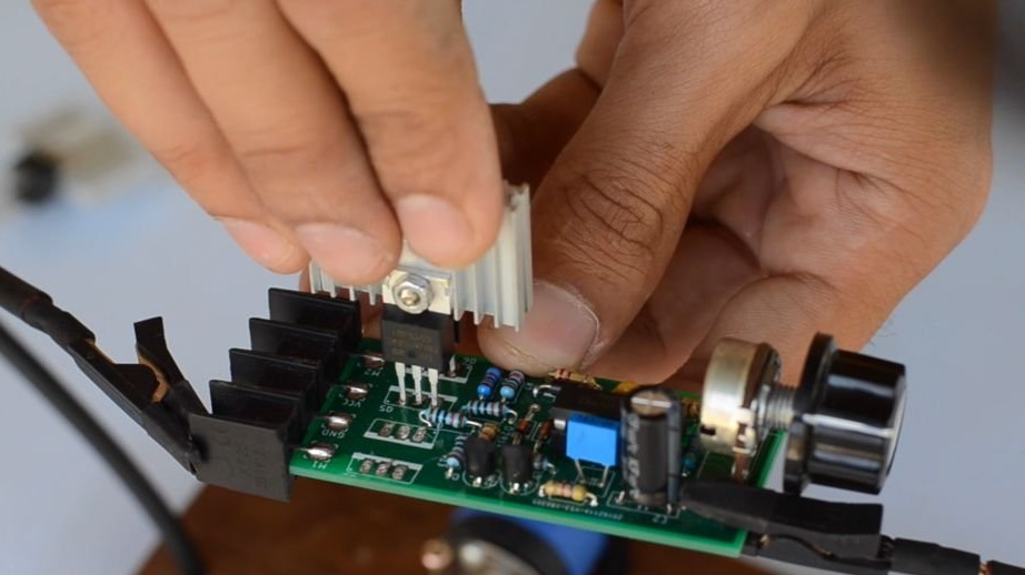
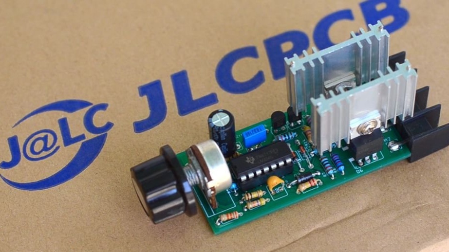
For this, a circuit was developed for a bi-directional speed controller based on the LM324 engine driver chip. Mosfets N and P channels are used to drive a large amount of energy. In addition, in order to ensure smooth operation, it was decided to build this speed controller on a printed circuit board, rather than a wall mount. The circuit board is designed in accordance with this scheme. Printed circuit boards were made to order, on one of the Chinese sites, namely JLCPCB.com. They are one of the largest PCB manufacturers in China. To order printed circuit boards, you need to download the Gerber files, and after downloading them, check the following parameters, such as the number, thickness and color of the printed circuit boards.
For the first order on this site, you can order 10 printed circuit boards, for only $ 2, taking into account the cost of delivery.
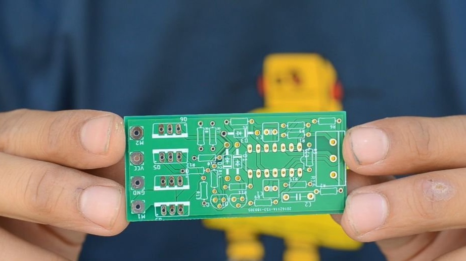
Printed circuit boards were delivered within a week and their quality is impeccable.
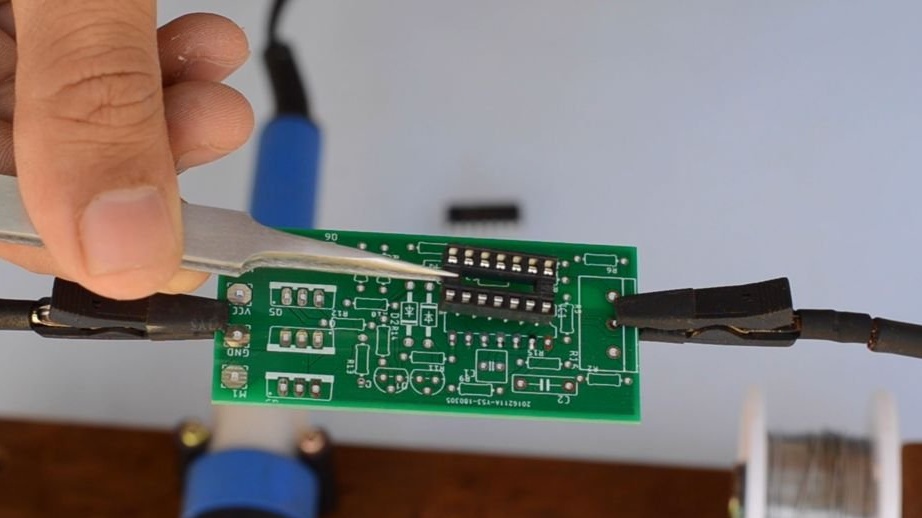
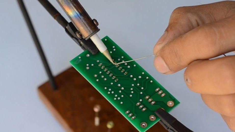
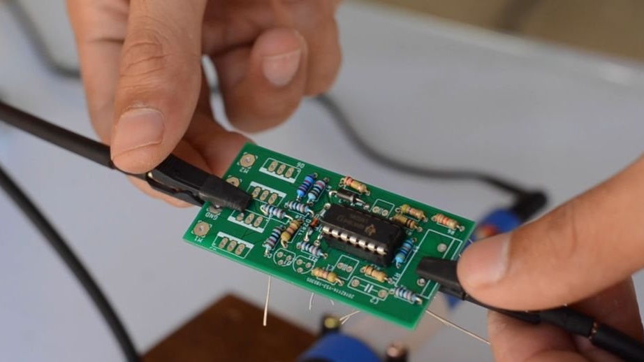
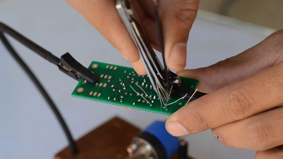
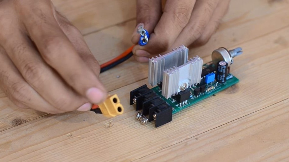
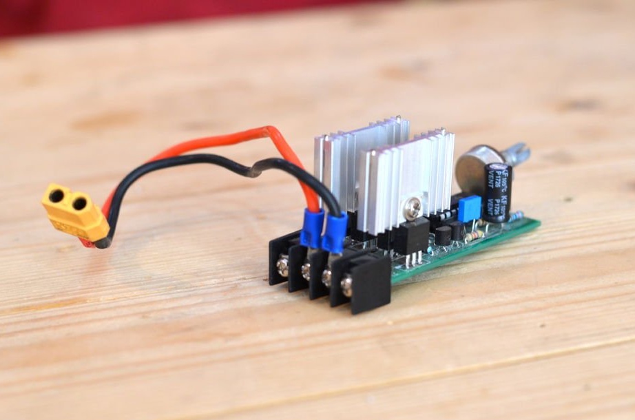
Later, all components were soldered onto a printed circuit board, as shown in the diagram.
After the speed controller is ready, input wires have been connected to the XT 60 connector on the other side.
In this case, the output wire goes directly to the engine.
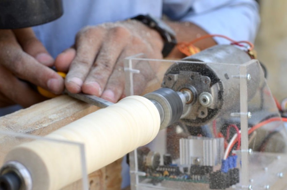
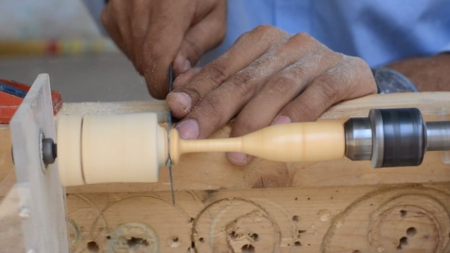
Step 7: Add Center Pin (tailstock)
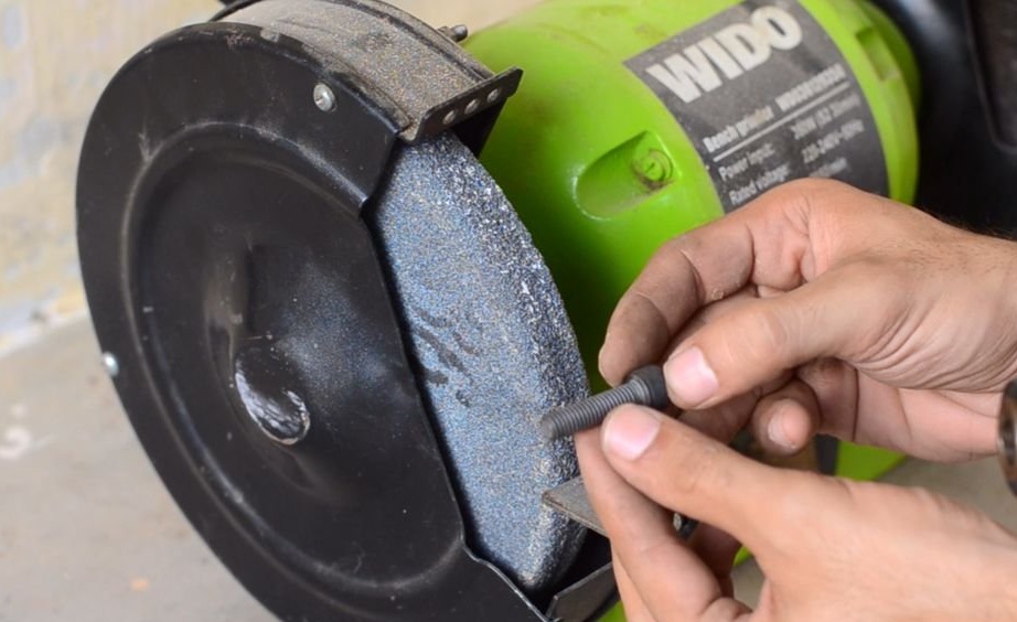
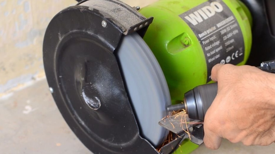
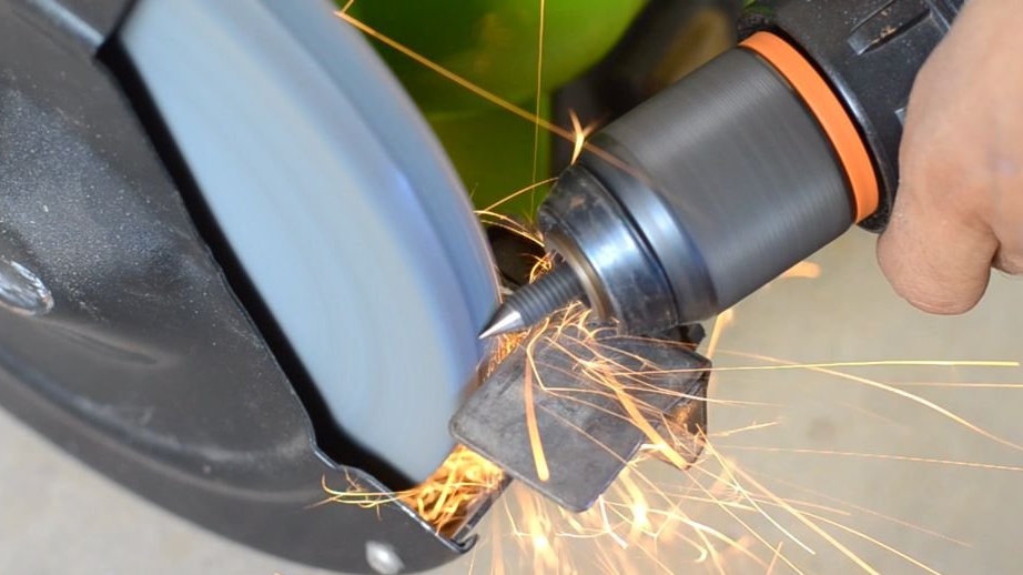
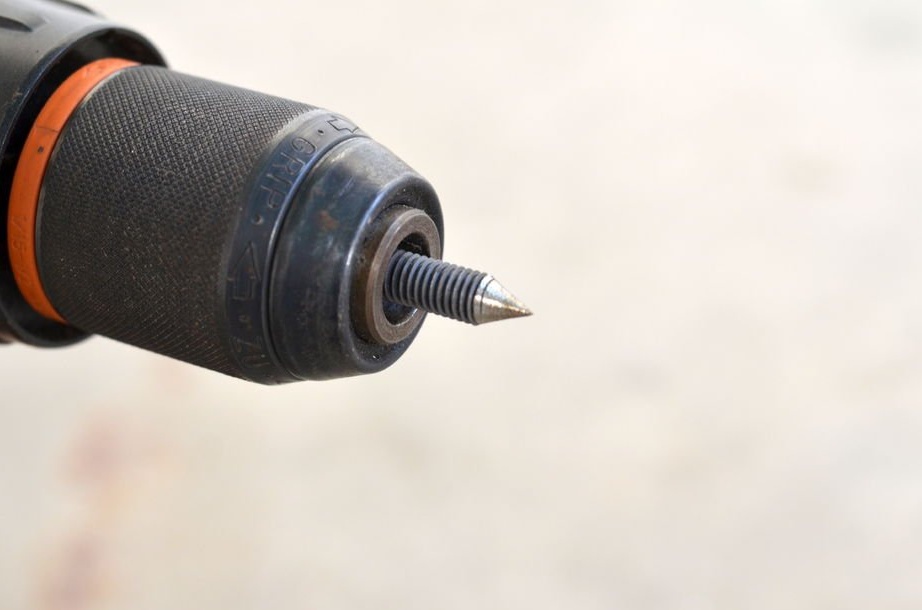
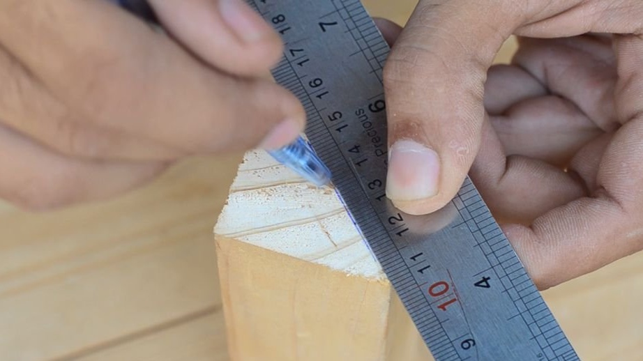
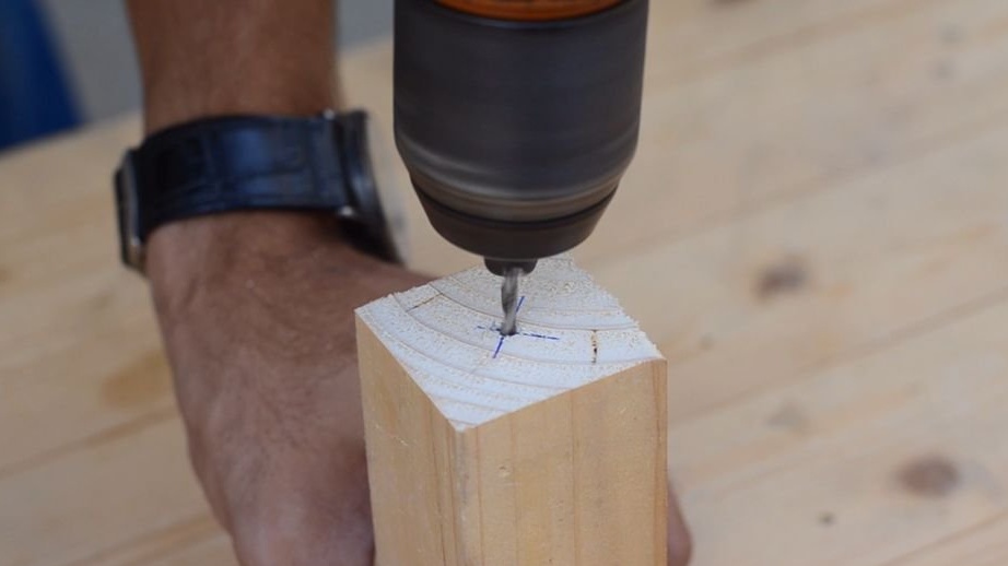
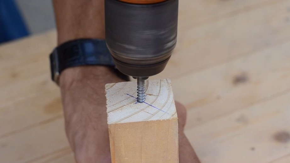
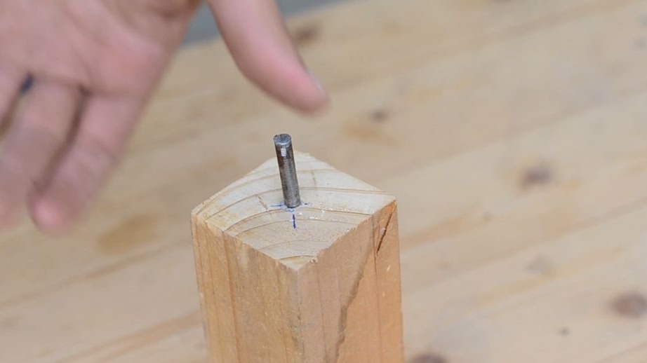
To hold the rotating element, a screw with a pointed end was made. The screw was sharpened using a bench grinder and drill. The screw was then tightened with a ball bearing nut to support the center point of moving objects.
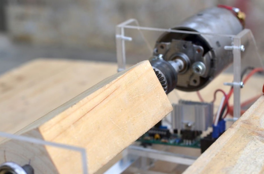
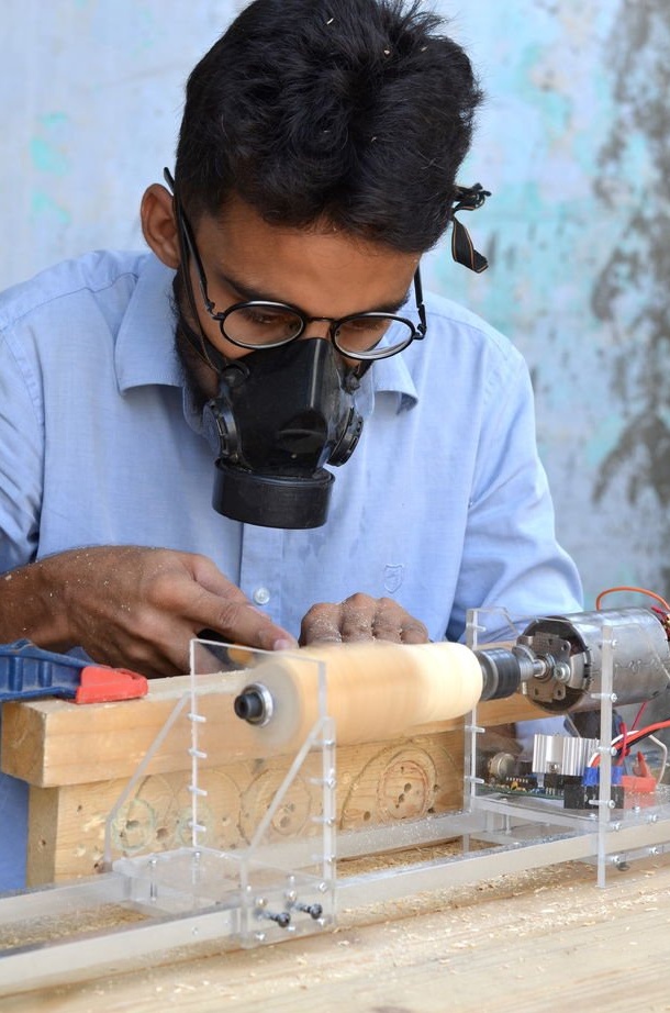
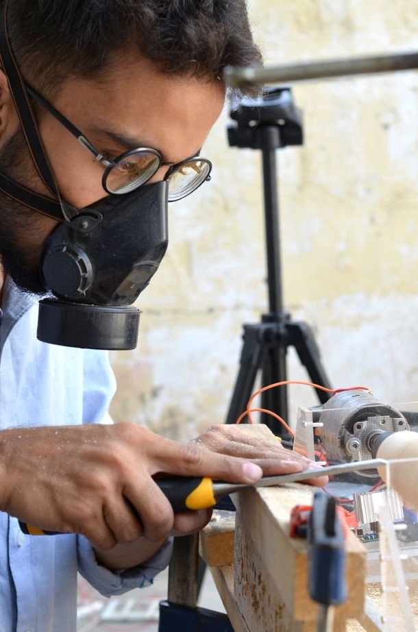
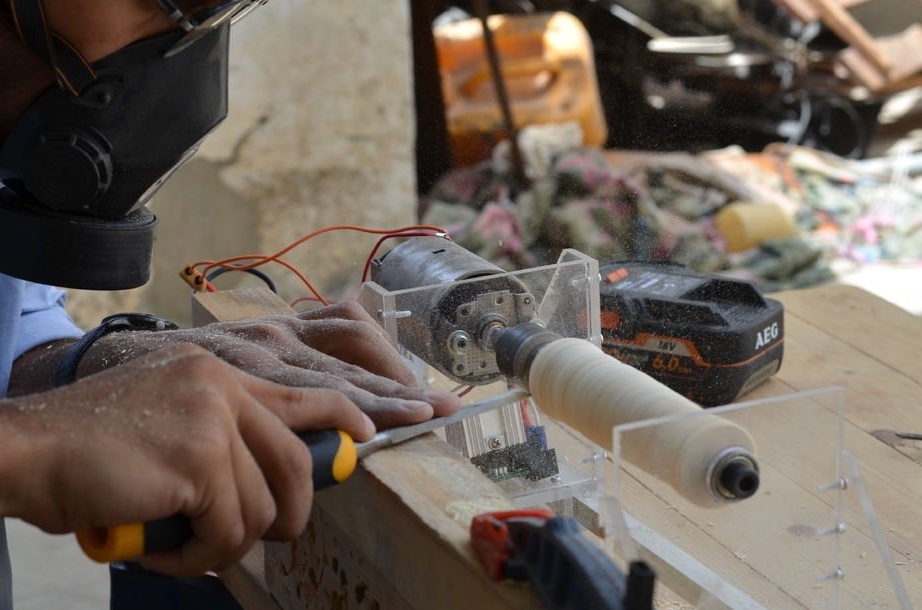
Step 8: Final Results

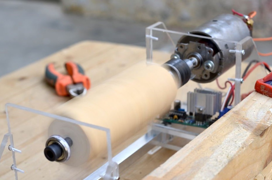


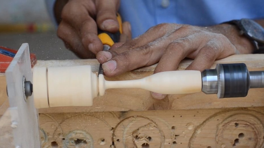
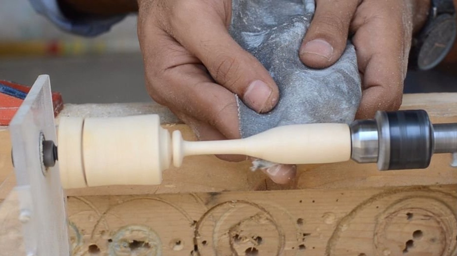
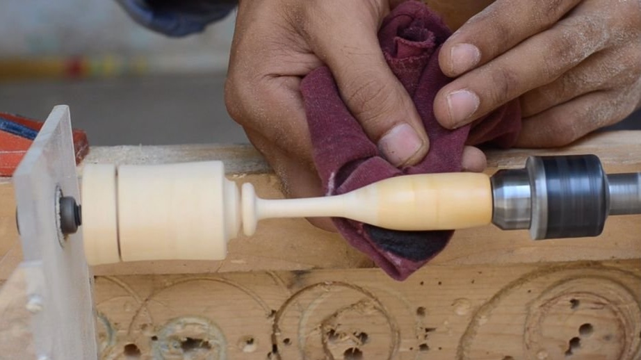

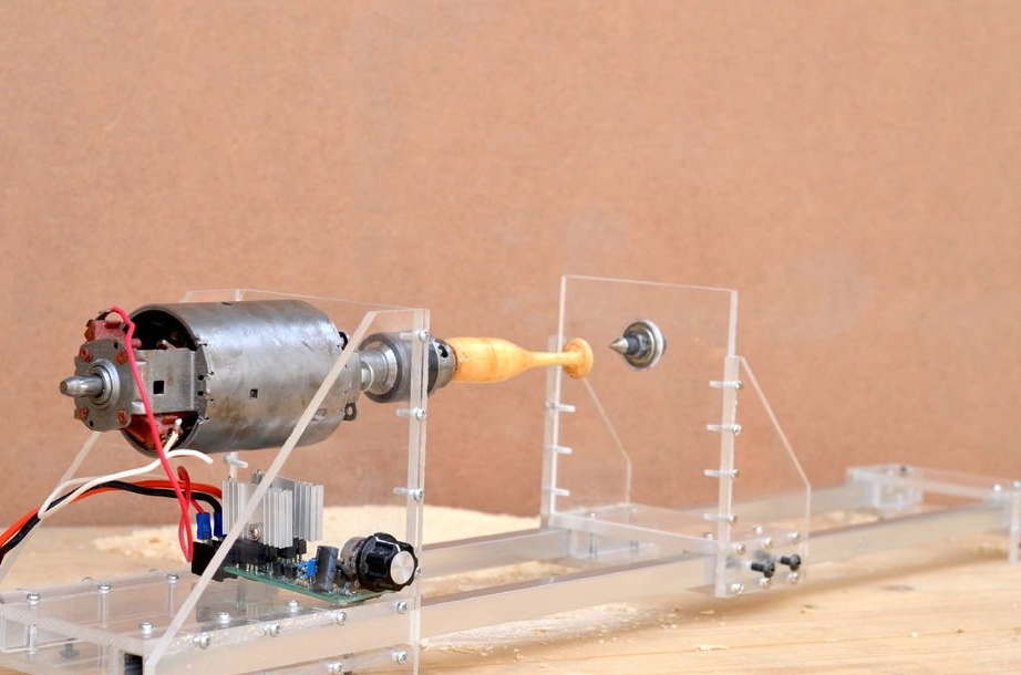

The project was successful, as everything works well. The only problem I encountered was that the power of the machine is limited by the adapter. Therefore, you have to use a hoverboard battery (self-balancing scooter), which can provide the necessary power. Battery operation can last up to half an hour continuous turning of wood.
The plexiglass structure gives the structure a neat appearance and is very durable, since not a single screw was unscrewed even after half an hour of continuous operation.
The manufacturing process of the lathe can be seen in the video below: