
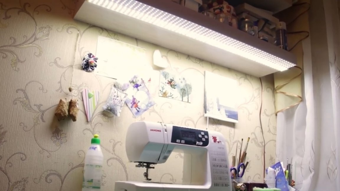
Today, together with the author of the YouTube channel "Tyap Lyap", we will manufacture a lamp from an LED strip. The installation technology is simple and has shown its effectiveness over the years of operation.
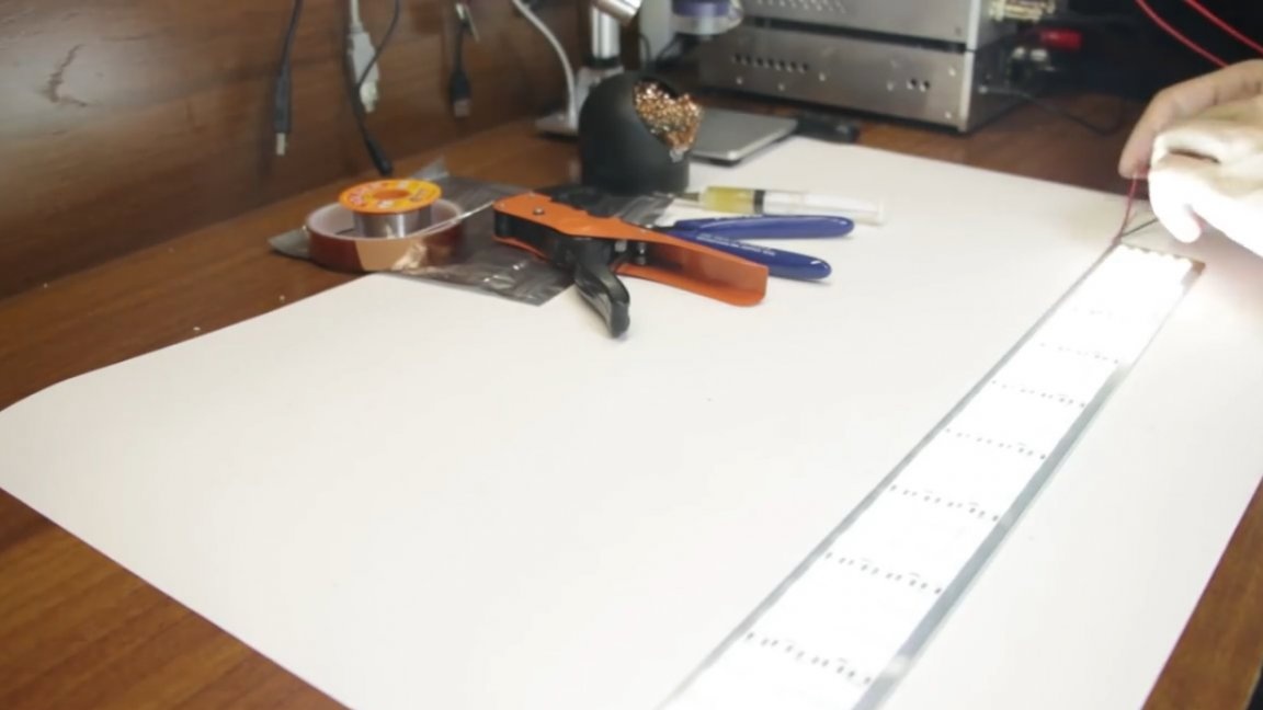
We need such an aluminum strip 1m long, 5cm wide and 2mm thick.
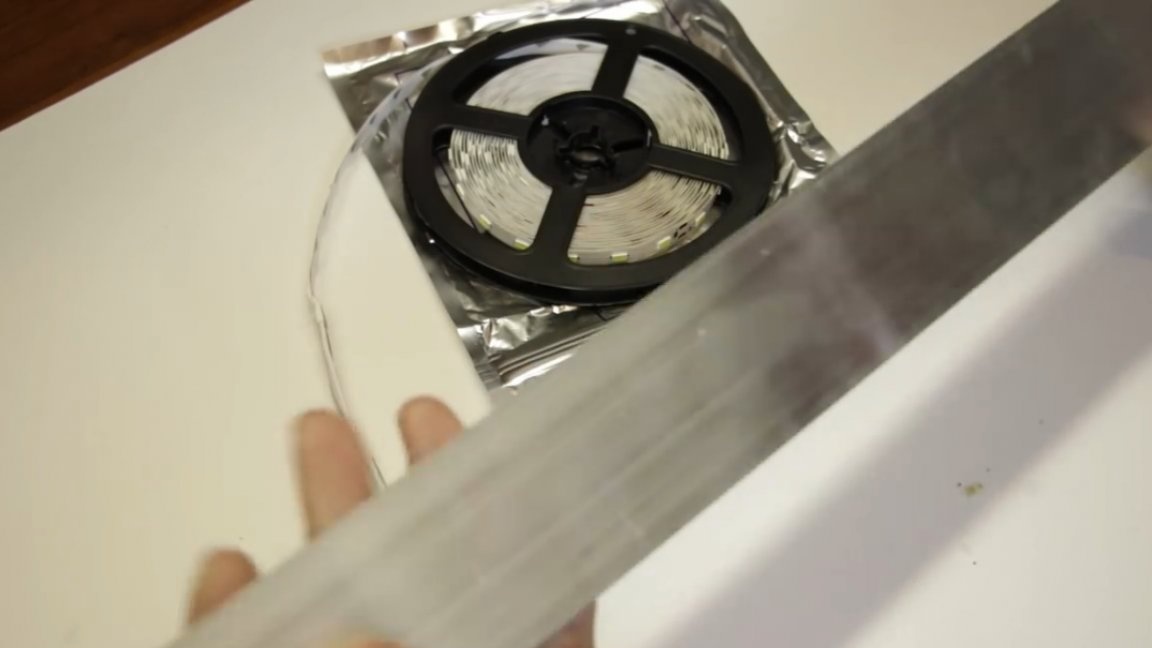
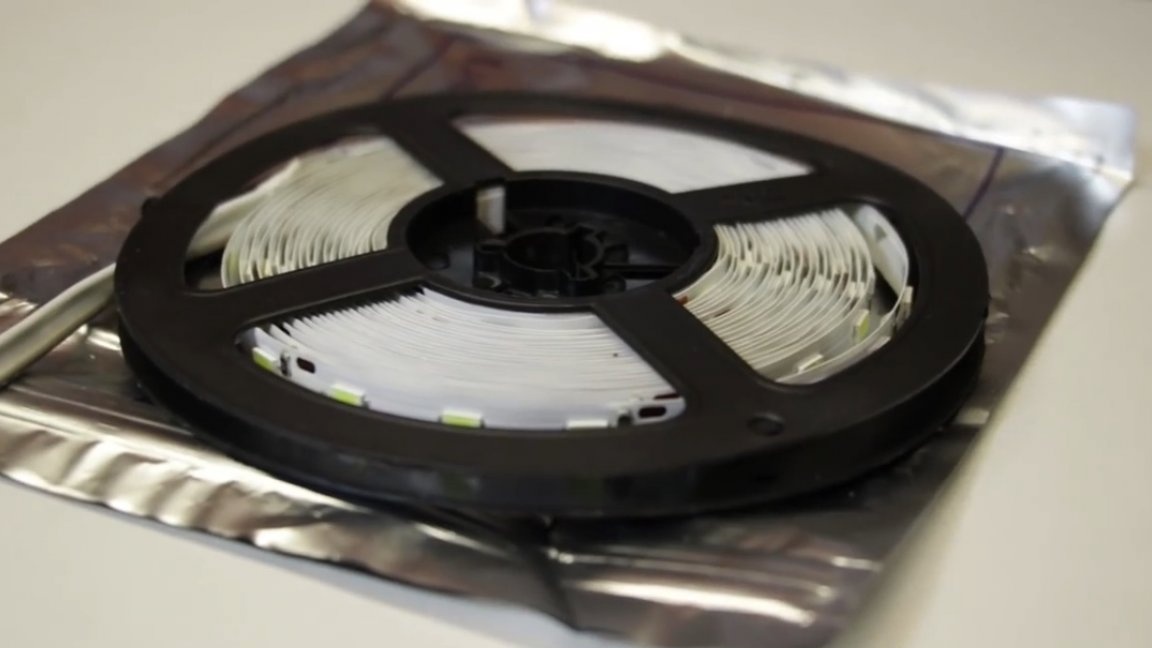
And also the LED strip itself.
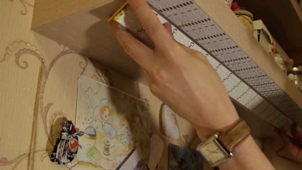
The tape is 5 meters long, so exactly 5 meter pieces are placed on this strip. The tape itself already has an adhesive base, only before gluing the aluminum must be thoroughly degreased. Well, we glue the plate on a double-sided tape to the shelf hanging above the table. You can’t imagine anything simpler; much more difficulties people have when trying to feed this creation. But first things first.
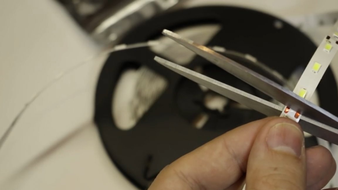
So, for starters, still let's put together a lamp. The first step is to cut the LED strip into 5 equal pieces. Since we have a 5-meter tape, therefore, in the end we should get 5 pieces of 1m each. The tape is cut at special contact pads, which are here literally every 3 LEDs.
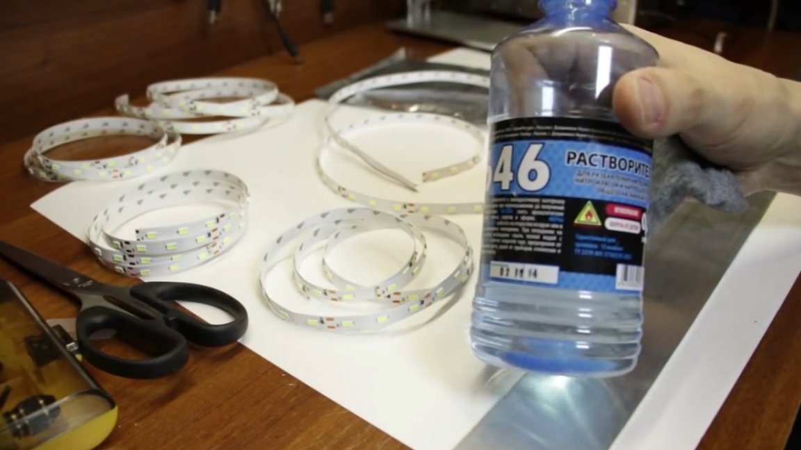
Then it is necessary to degrease the aluminum plate, an ordinary solvent will do.
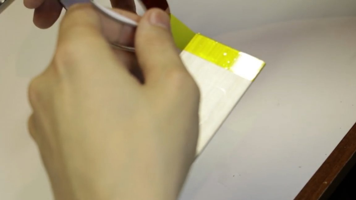
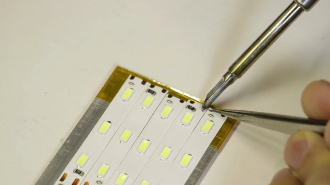
The edge of the plate must be wrapped with kapton tape to avoid contact of the conductive parts with aluminum.
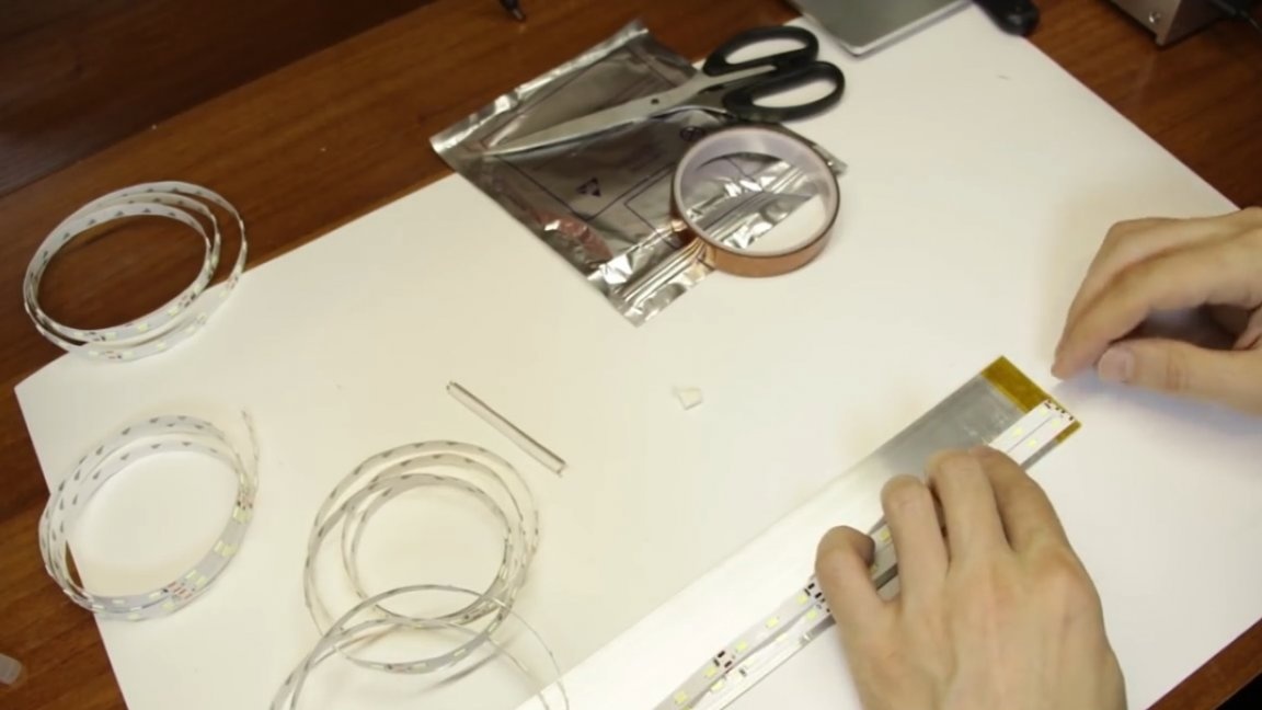
Next, proceed to sticking the tape.
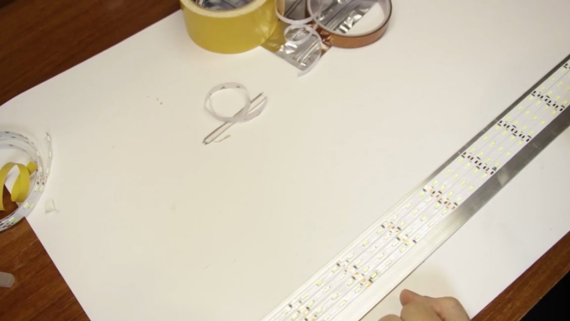
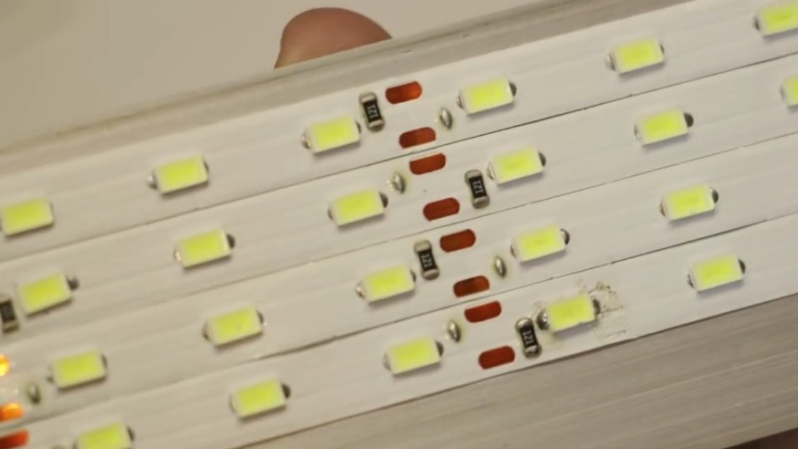
Until that moment, the author ordered a lot of LED strips in China and all of them were assembled (soldered) from half-meter pieces. The same tape is one-piece, apparently the Chinese have changed something in their technologies. But without jambs, it still could not do. Apparently already at the time of testing it turned out that 1 LED was dead and they replaced it, soldering traces are visible.
And one more mistake.
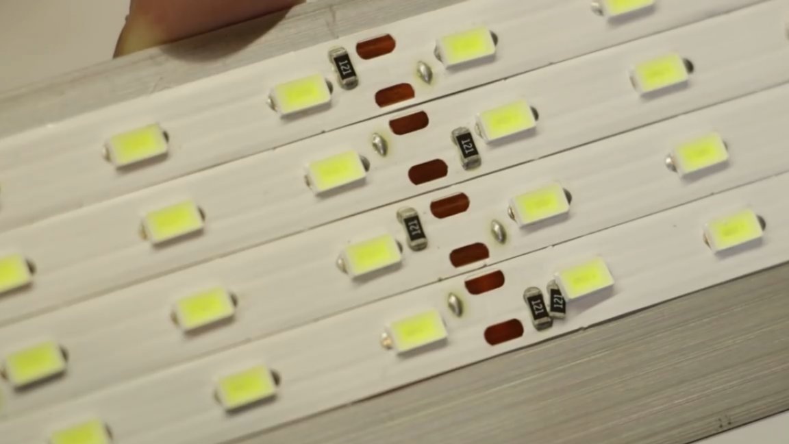
In one place, as you can see, an extra resistor has stuck. How he got here is incomprehensible, but now part of the resistor acts as a conductive track for the LED. Surprisingly, everything works.
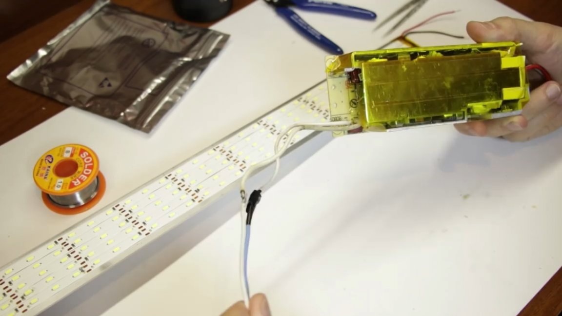
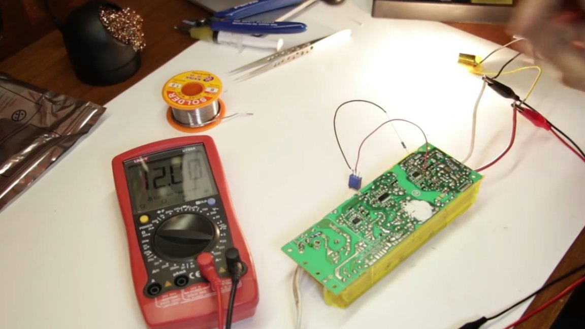
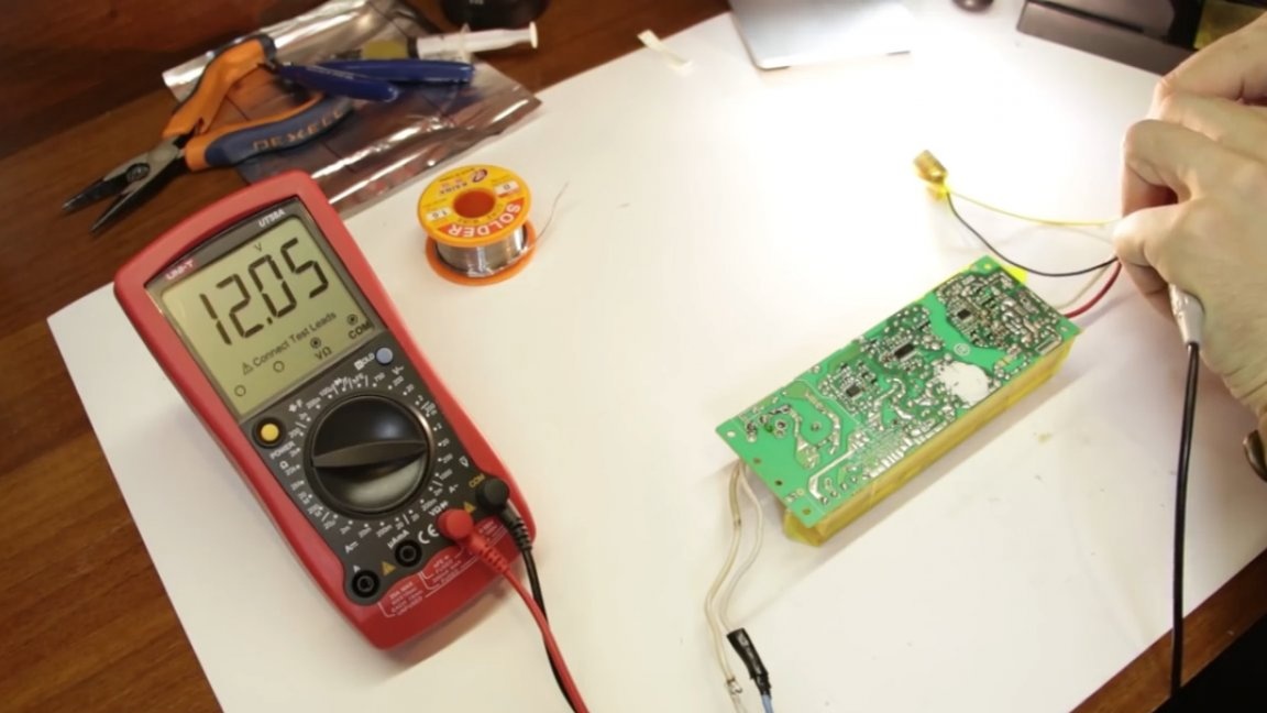
That's it, we soldered the lamp, let's connect it. To do this, apply 12V power to it.
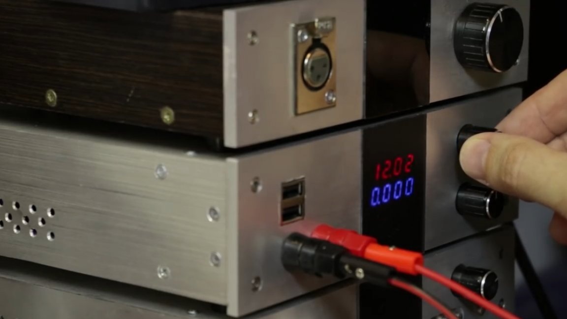
As you can see, everything works great.Now the tape consumes a current equal to 1.6A, but as the LEDs warm up, it is quite possible that this current will increase, 1.7A will at least be consumed, so you need to calculate your power source from these numbers.
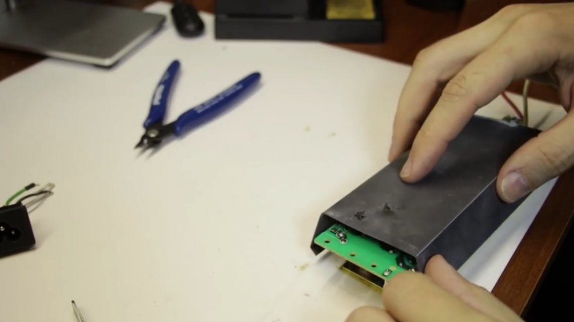
The driver for the tape needs to be selected with a margin (approximately 20 percent), so specifically for this tape, a source somewhere around 2.5A (2-2.5 minimum) would be suitable. The author will use an adapter from some ancient laptop as a source. The adapter is powerful, at the output of as much as 6.5A, this will allow 2 tapes to be fed from it immediately.
And now we have to redo the adapter and get the required 12V instead of 19V. If you do not have the right power supply or just do not want to bother with its alteration, then, for example, on the Aliexpress website you can easily find different LED drivers, choose to your taste and color.

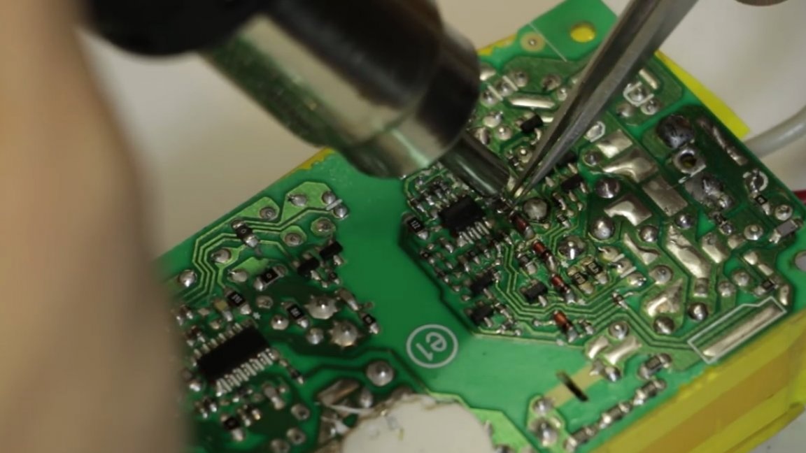
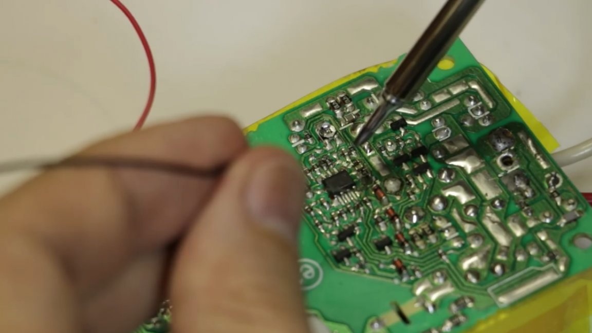
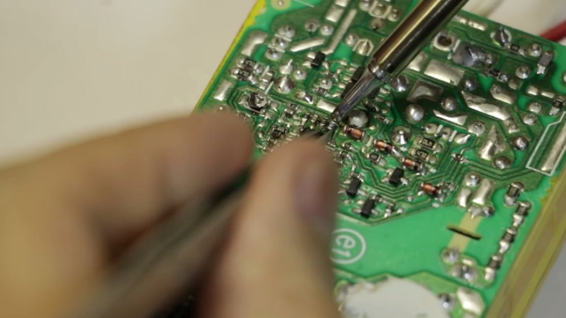
As mentioned above, the author will immediately power 2 lamps from this power supply. But this notebook power supply has an output voltage of 19V, and the ribbon, as we recall, is 12-volt. The alteration is actually not so complicated. The author found this method once upon a time on the Internet and still successfully uses it when necessary. All similar switching power supplies in their low-voltage part have a PWM controller, in this case in the form of such an 8-foot microcircuit.
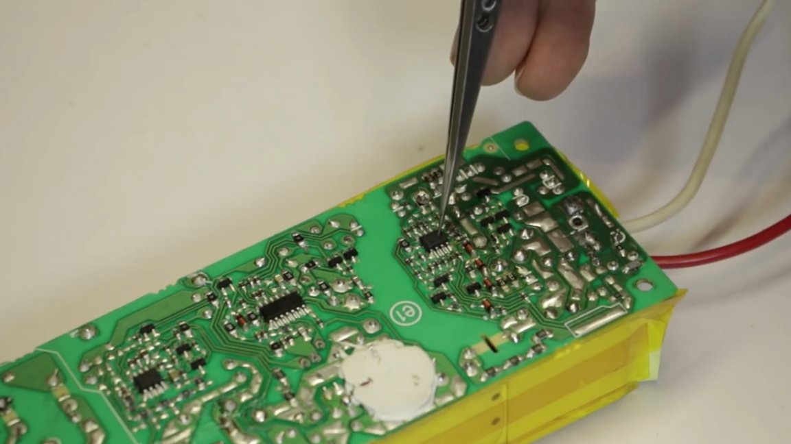
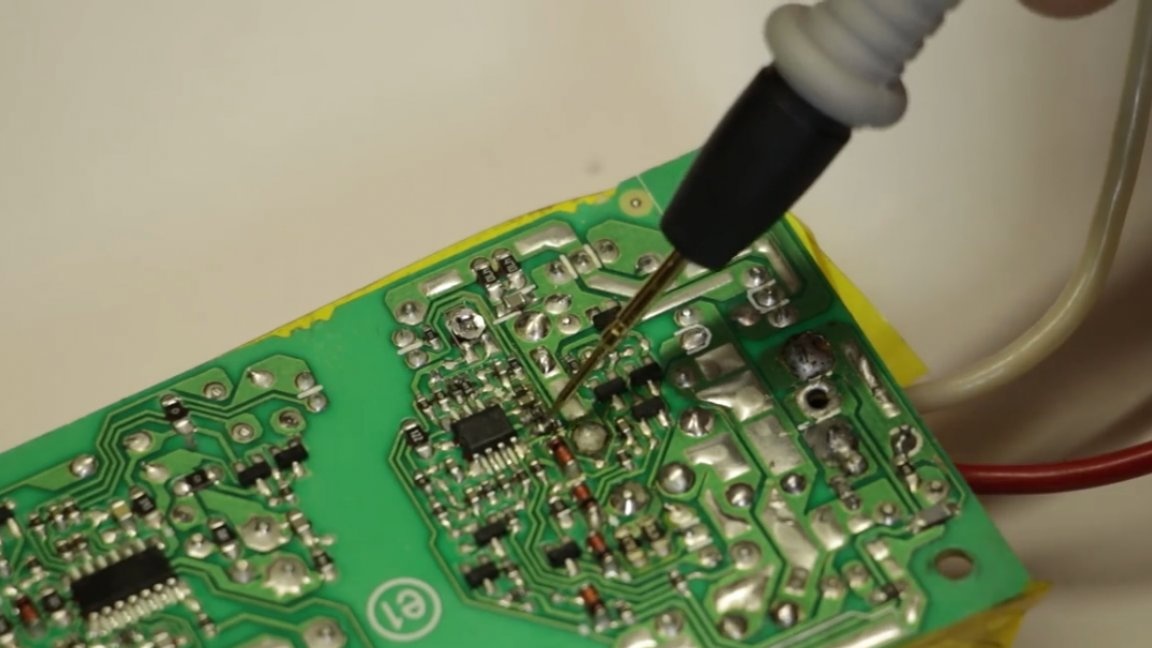
It manages power keys based on the information that comes through the feedback line. So, it’s precisely this feedback that we need to make a little bit of tack. This is done by changing the resistance of just one resistor, you just need to find the right one, and they are like bugs here. The author searches for it by simple dialing, the desired resistor is located between the positive terminal and the PWM controller. True, some sources write that it can be between the minus, but apparently it depends on the type of chip. So, we put one probe on plus, and the second we call the resistor around the PWM controller.
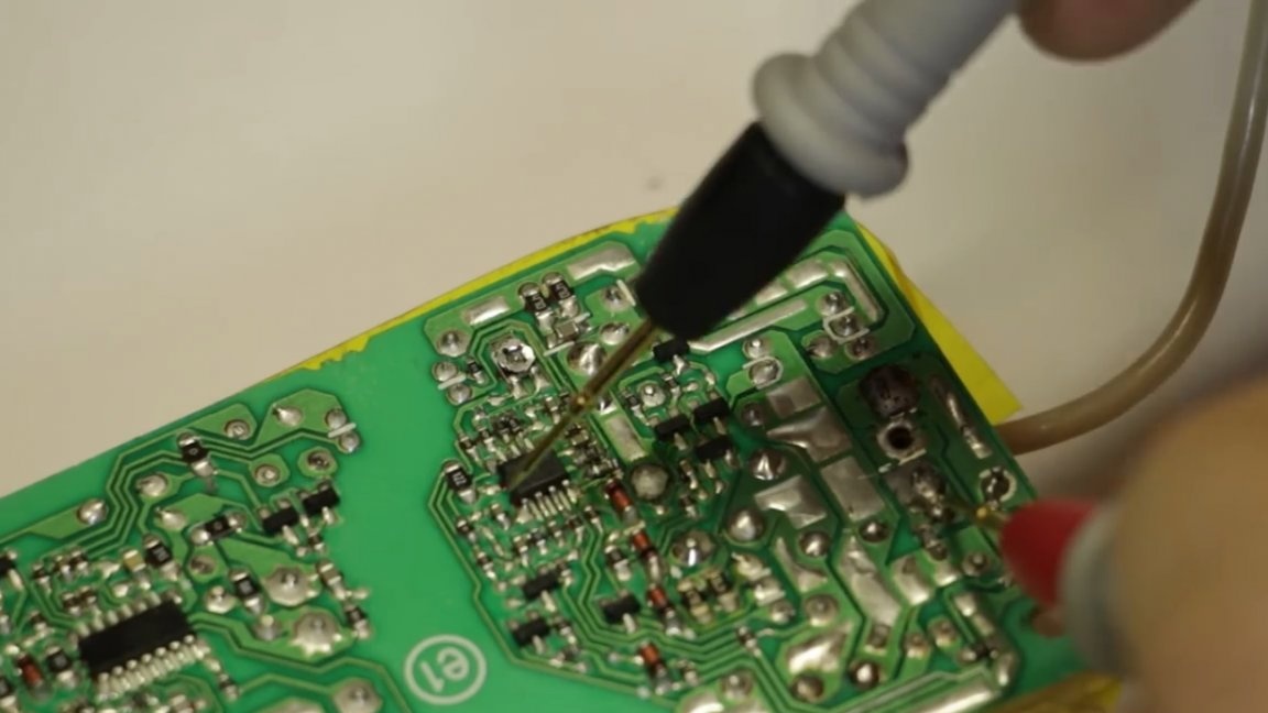
You can of course find the datasheet and figure out the circuit, but there are only two combinations and, if you're lucky, then the first resistor will be ours.
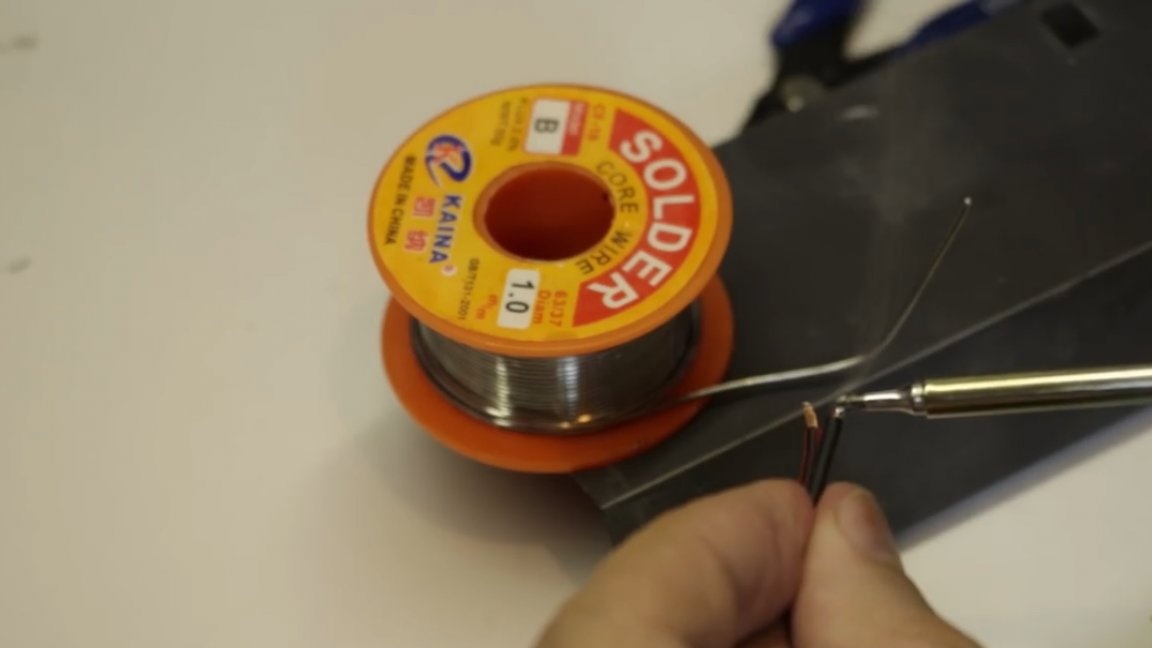
Solder the resistor. Let's start with the extreme.
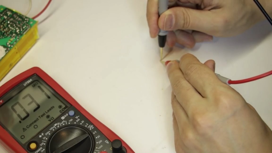
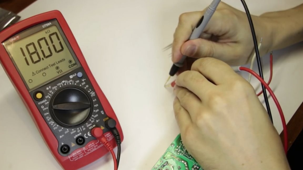
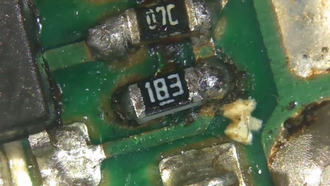
Now we need to find out the resistance of our "microbe". Its resistance is 31kOhm.
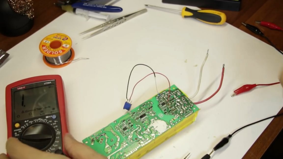
The next step is to select a variable resistor or a trimming resistor of a similar value and solder it into the chamber. The author did not have a trimmer for 30 kOhm, he was available for 10 kOhm, so in series with him he soldered a 20 kilo-ohm resistor.
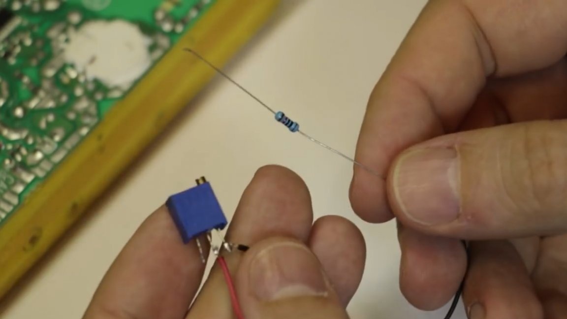
And now this garland must now be soldered to the place of the native resistor. But before soldering this garland, we must of course set up the necessary 30 kOhm, and then actually we don’t need to think anything, just twist the trimmer to the end so that in total we get the same 30 kOhm that we need.
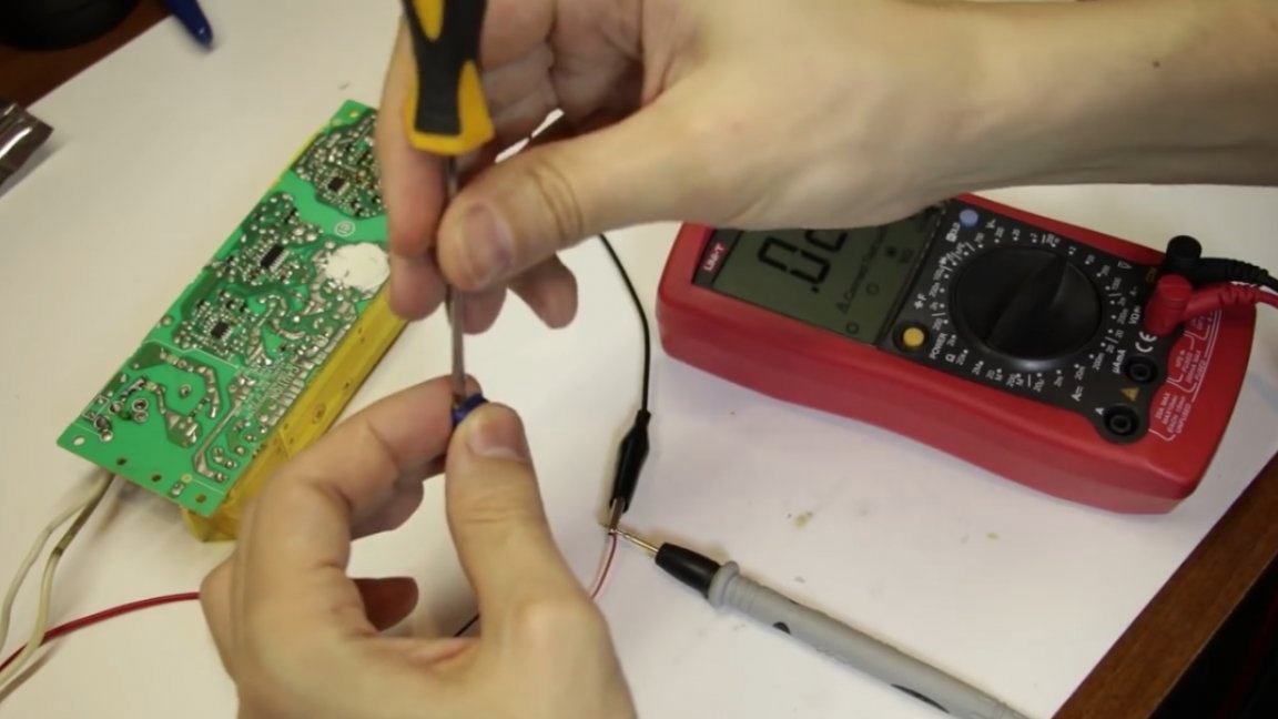
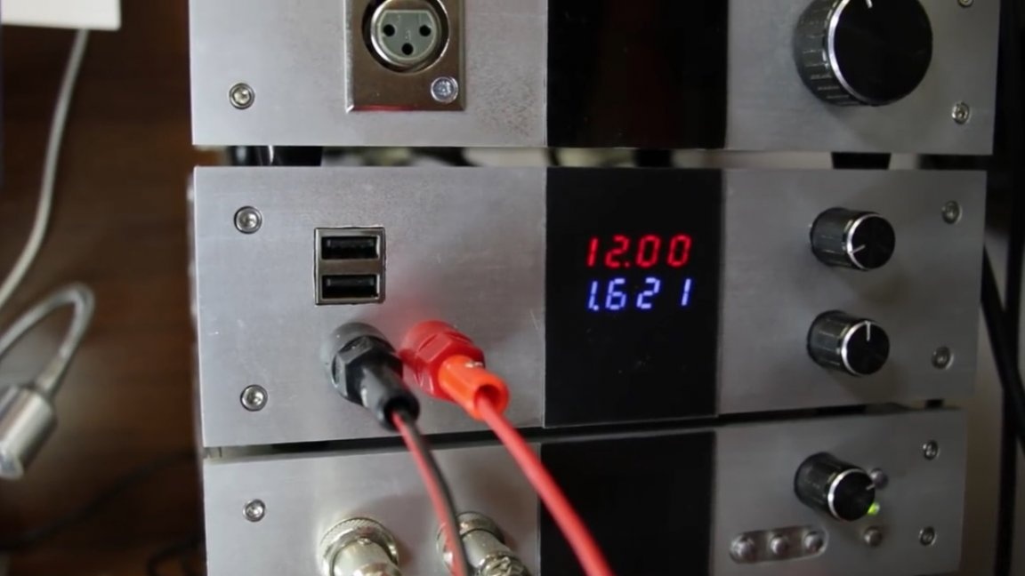
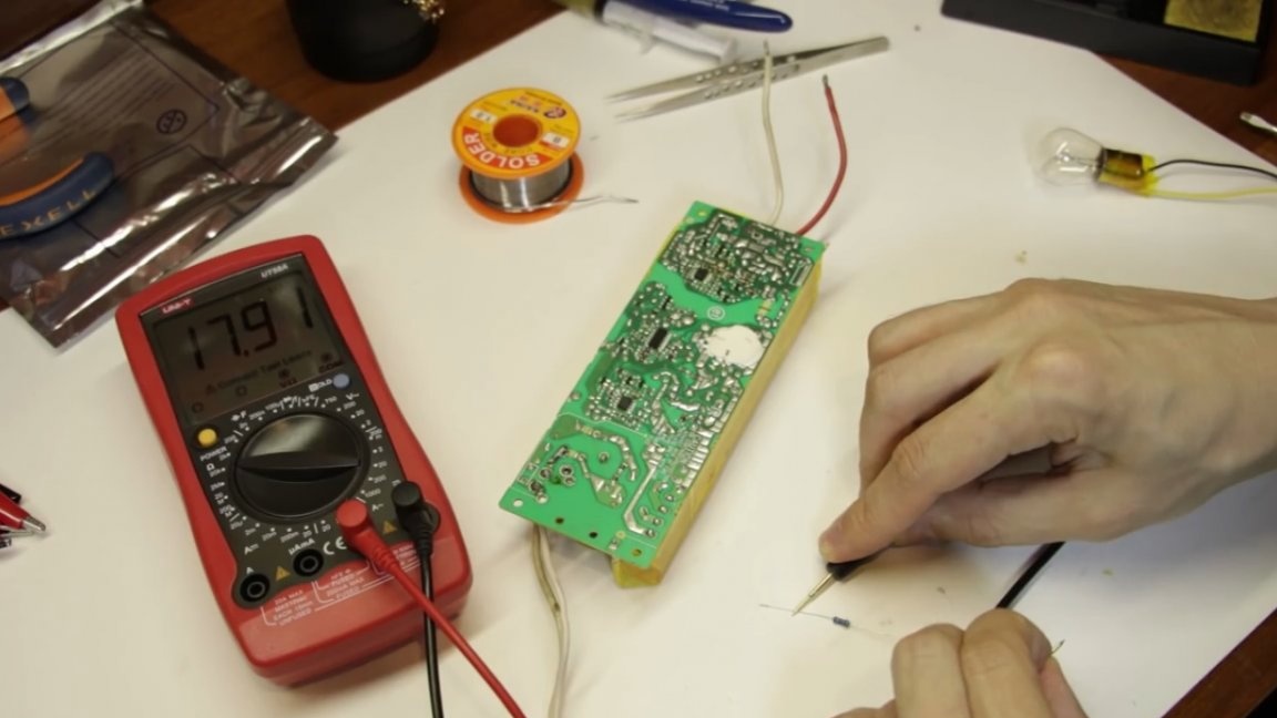
When everything is soldered, we hook the multimeter to the output and try to get a 12V output at the output of the tuning resistor, unless of course we guessed with resistance. We turn on the adapter, at the output we have a rated voltage of 18.5V, but let's turn the variable resistor, and as you can see, the voltage drops.
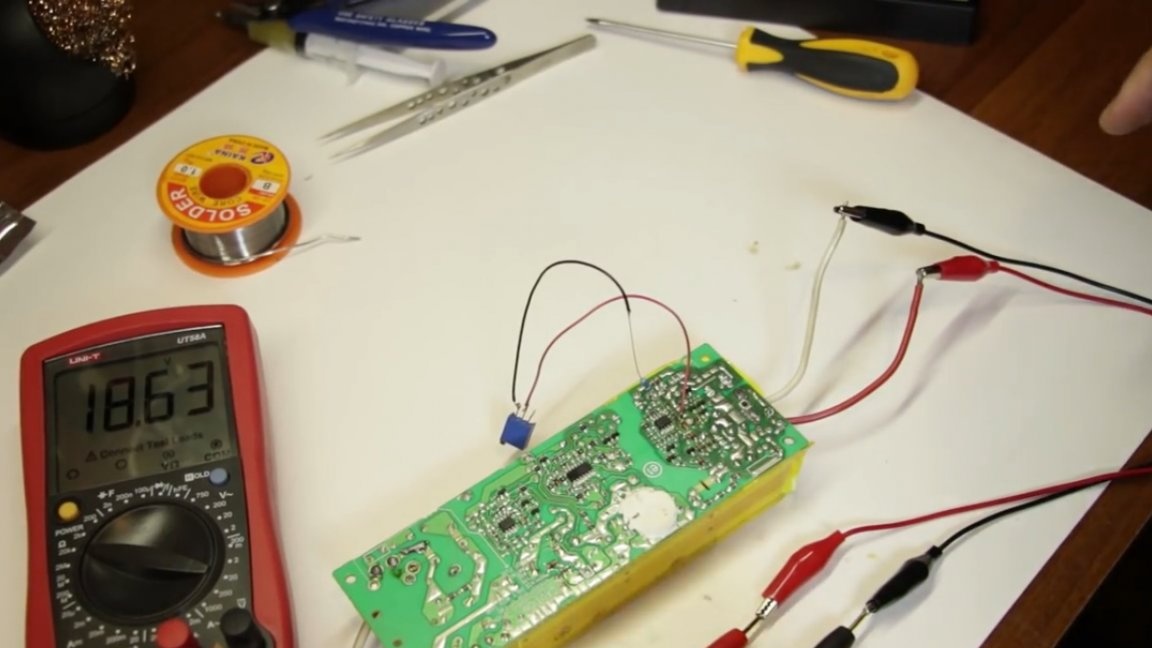
Well, now we need to set the 12V we need. For fidelity, we connect a 12-volt light bulb as a load and set exactly 12V at the output.
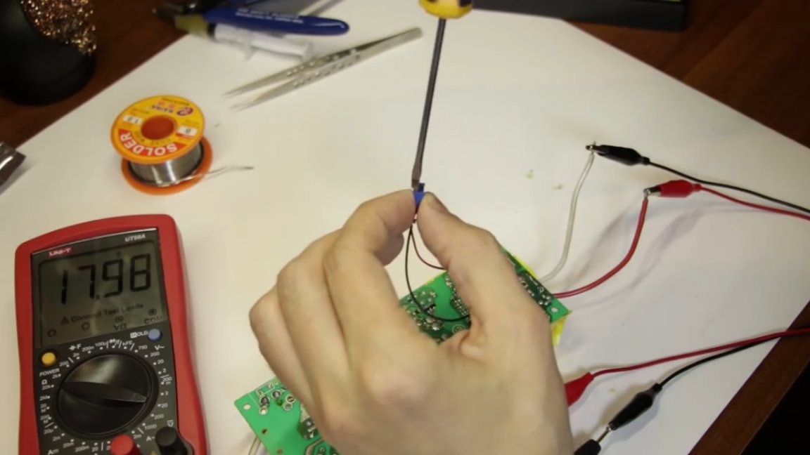
That's it, now you can solder it all out, measure how much resistance you end up with and solder another SMD component with the face value to this place, which you get here in this garland.
So, the resulting resistance is 18 kOhm (17.9). We find the resistor of the right size and the desired value and solder it to the board.
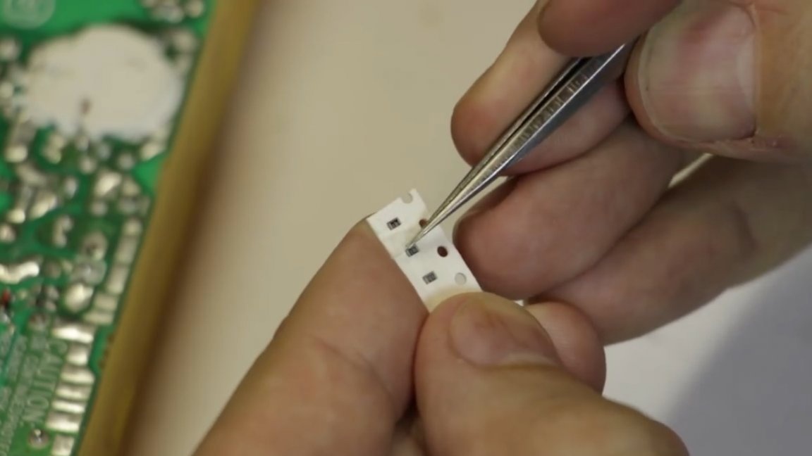
Very small, so it is better to check the quality of the solder to sleep more calmly.
Well, everything seems to be fine. Well, we check immediately with the load in order to exclude a voltage drop.
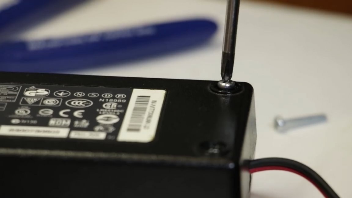
In general, everything works fine, you can collect all this into the case and connect our tape already in place (well, in this case, 2 tapes).
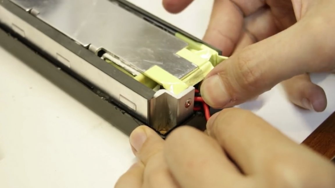
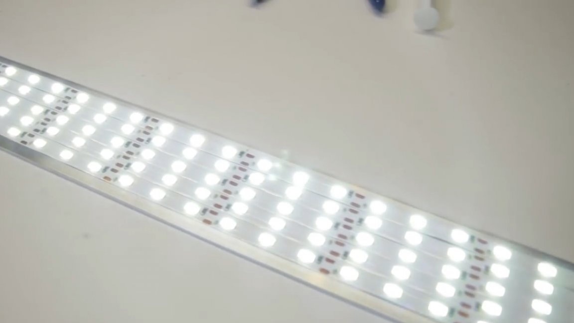
Well, everything is ready. The author connected the lamps in parallel.

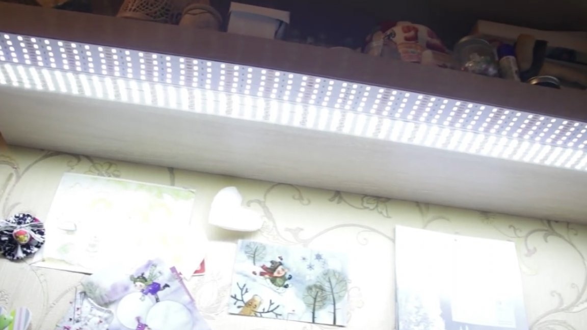
It can be seen with the naked eye that the new tape is much brighter and now there will definitely be enough light. Well, that's all for today. Thank you for attention. See you soon!
Video: