» Electronics » Amplifiers »DIY tube sound amplifier

DIY Tube Sound Amplifier


This tube amplifier is designed and built from the ground up. This is a very long project, and it took a lot of time and patience from the author of this project. Let's analyze all the pros and cons of this homemade together with the author.

IMPORTANT! This device has a deadly voltage inside. If you do not know about high voltages and electronics, then it is not advisable to repeat this homemade. Otherwise, you do this at your own peril and risk! It is not recommended to delve into the device with electronic lamps while it is on!

Step One: The Idea itself

DIY Tube Sound Amplifier


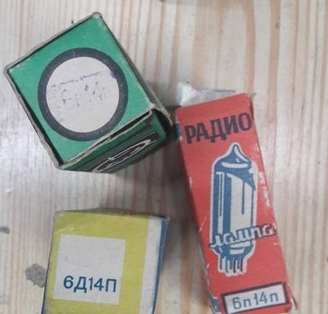
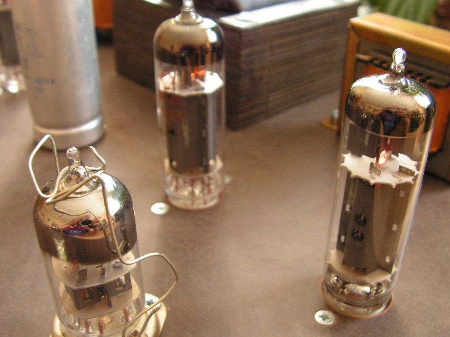
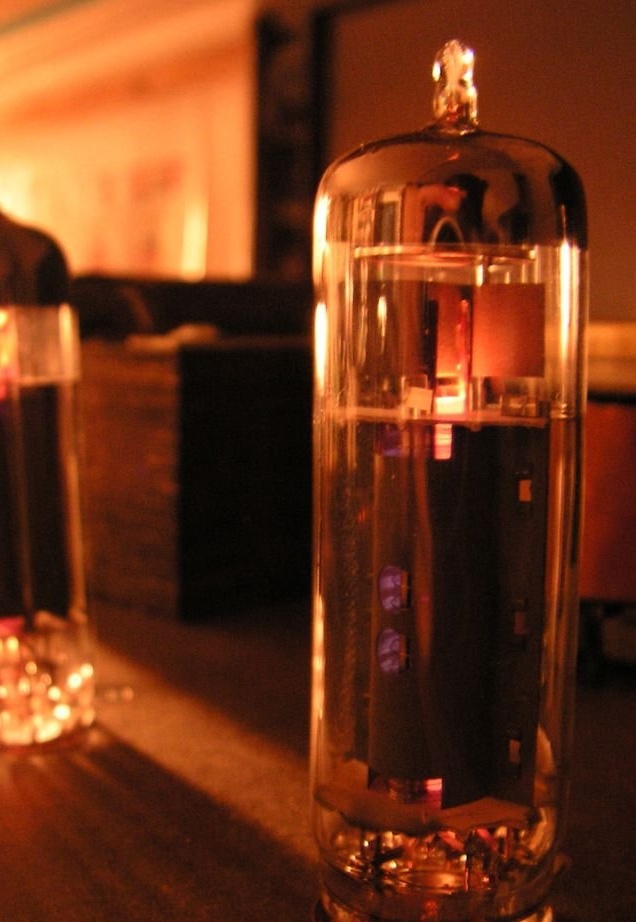
Several old lamps were found in a box in the house of grandparents. It was decided to make a low-frequency amplifier based on them. Other semiconductors in this homemade product were not used in principle. I had to conduct a study to find out how these tube amplifiers work.

Step Two: Circuit and Components


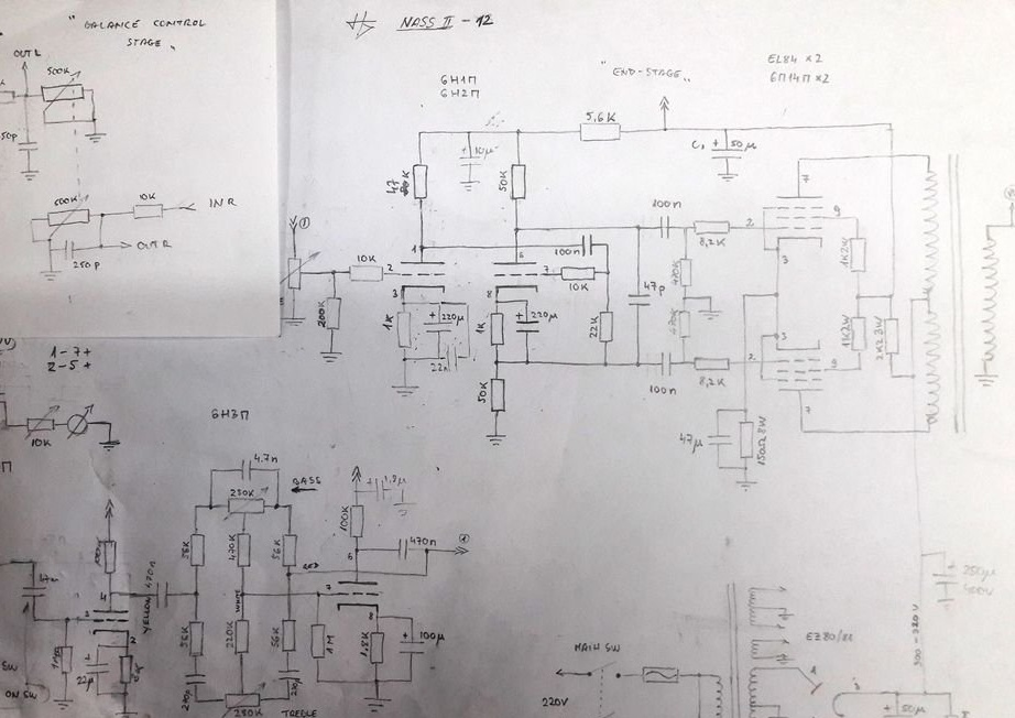
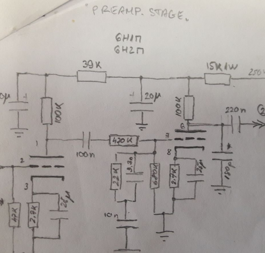
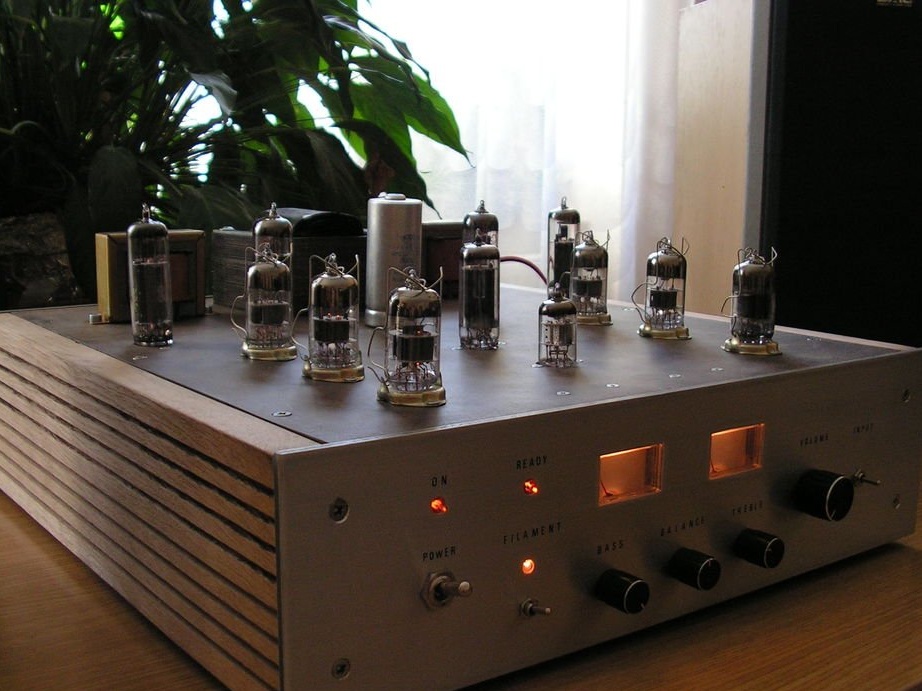
Designing the circuit was probably the most difficult part of this project. First, a list of the tubes that were available was written, and then, based on them, a schematic diagram of the project was drawn. A push-pull stereo amplifier with tone controls, phono and aux inputs and some VU meters was designed. EL84 c lamps were required, and for other steps it was decided to use simple double triodes. The lamps quickly ran out and had to order new ones.

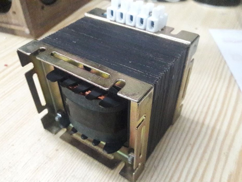
Then the time came for another difficulty: an output transformer. A cheap transformer was not easy to find. But after a little search, in the end, the transformer was found on one popular bulletin board. The transformer is designated as NASS II-12 in the diagram. “NASS” means “Not A Single Semiconductor”, II means push-pull and has a total of 12 legs.

Step Three: First Test


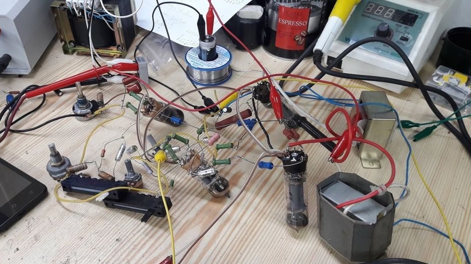
The chaos on the table above is the assembly of components in the air.
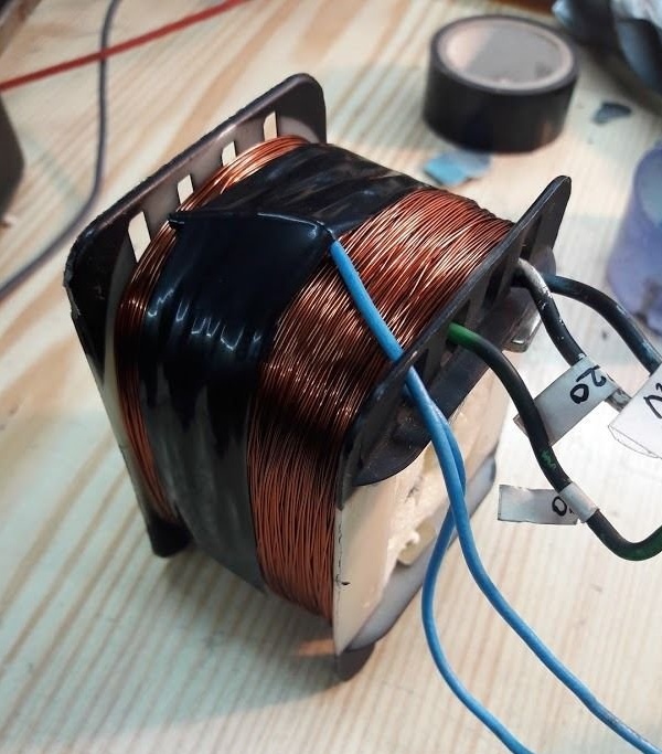
Two conventional power transformers are used here in series as an output transformer, just to check if everything is working. Everything seemed to be in order, and now it's time to find a power transformer. An old transformer was lying in stock and the author made an attempt to wind the transformer himself. However, after disassembling, rewinding and testing, I had to, abandoned the idea ... Therefore, one transformer was taken from the old radio, thinking that everything would be in order. But this is not so. But more on that later.

Step Four: Product Housing


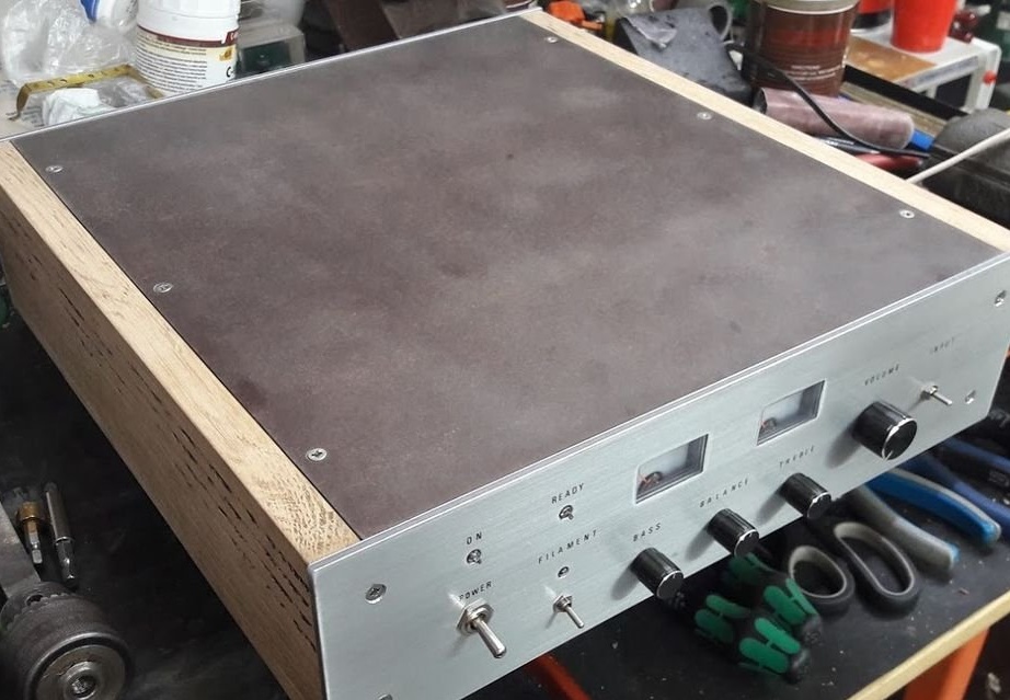
The material for the case was to be aluminum. Brushed aluminum front, top and back plate. Hand made of some solid wood. Unfortunately, the author had to abandon the aluminum top cover because resources were limited. The front and back were made of a three-layer material (two sheets of aluminum and one plastic between them). The top cover required strong and durable material, because it had to withstand the heat generated by the lamps and withstand the weight of the main transformer. Therefore, the decision was in favor of the PCB. This material has a brownish color, it is relatively durable and easy to work with.

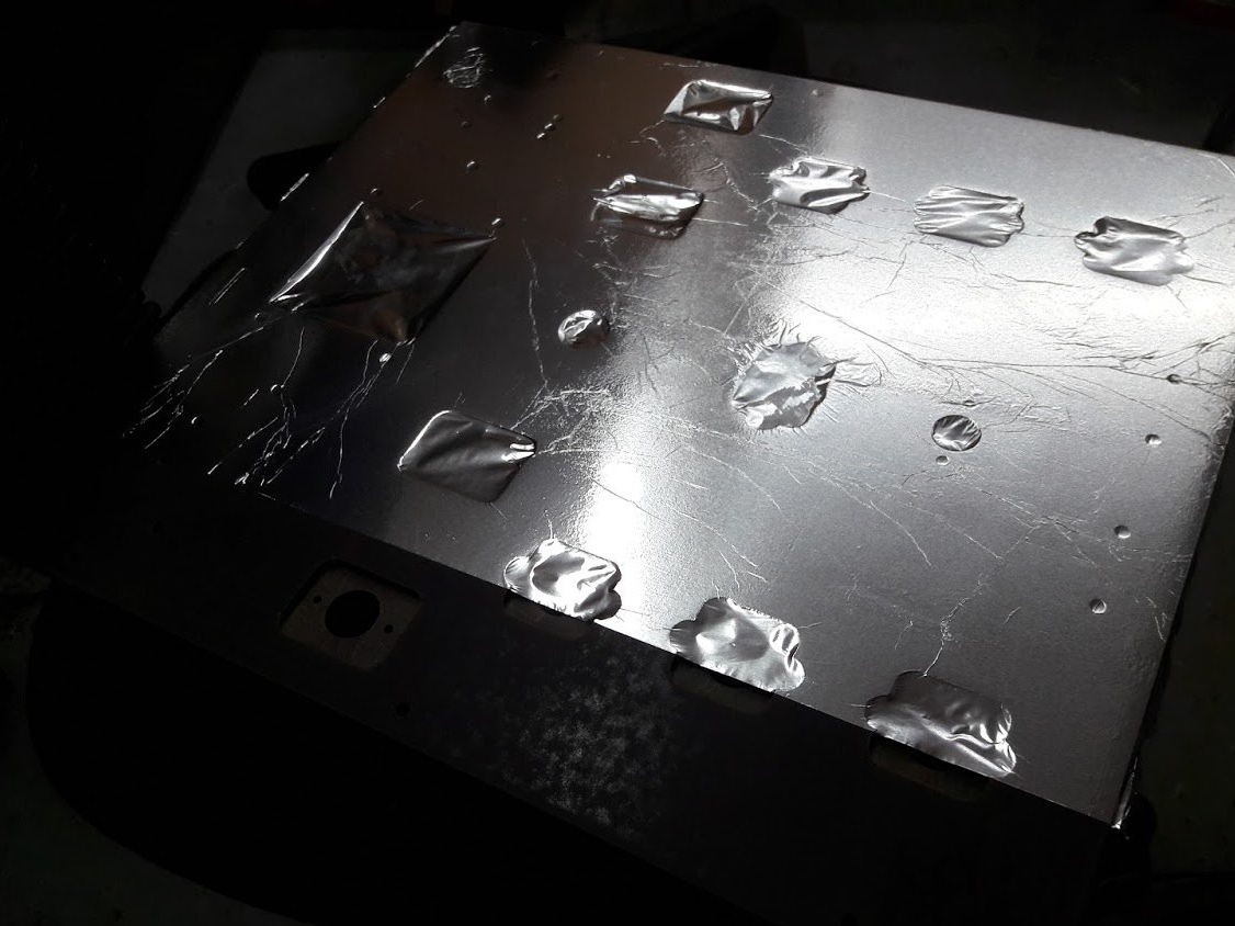
Important! It is necessary to electrically shield the entire housing and connect it to the ground at only one point in order to avoid ground loops. In this case, aerosol glue and a thin aluminum radiator were used.

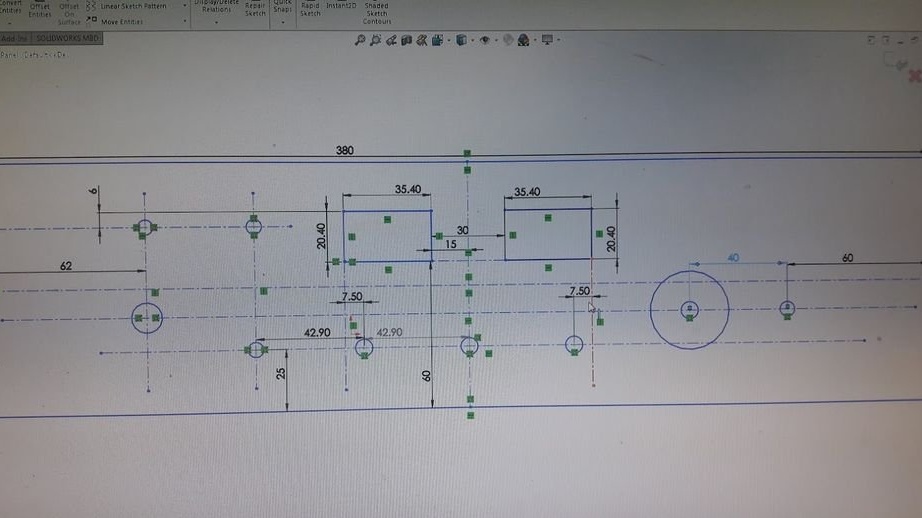
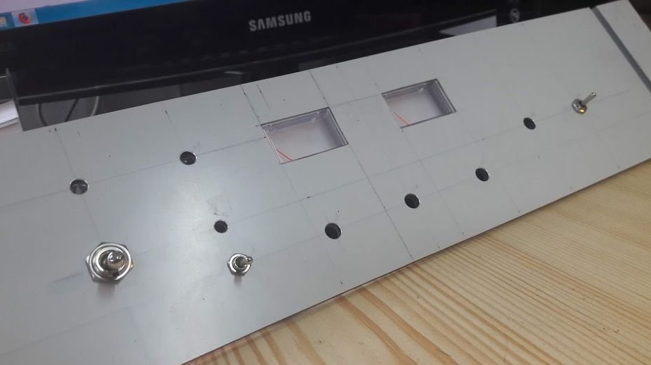
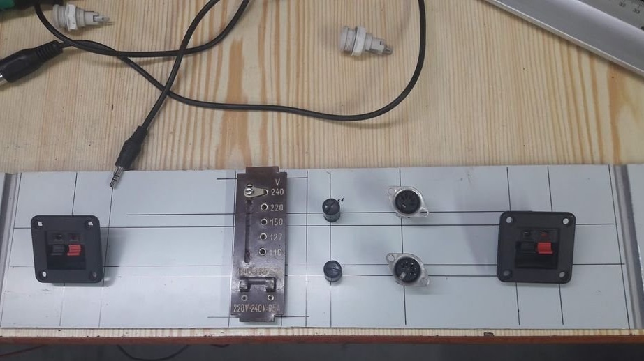
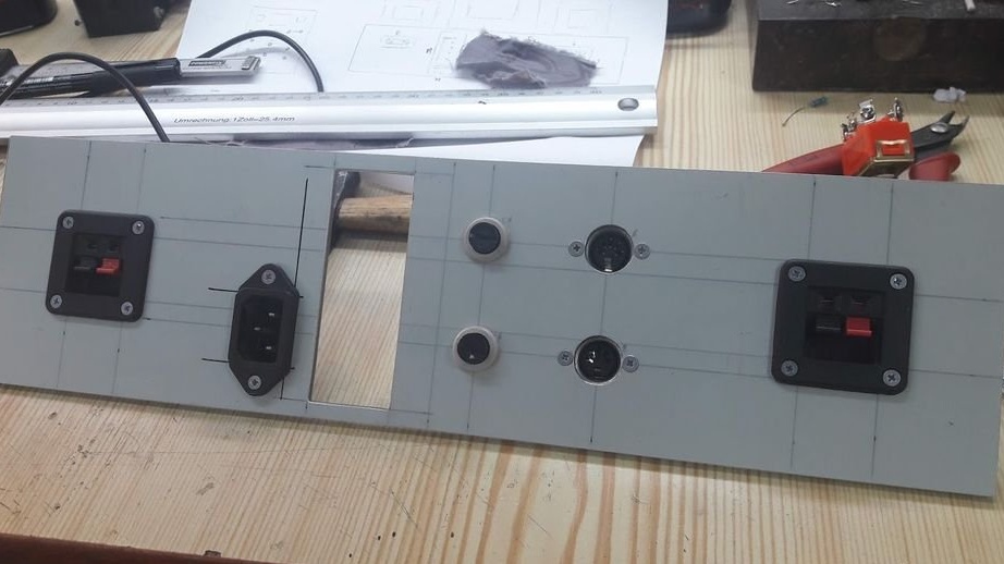
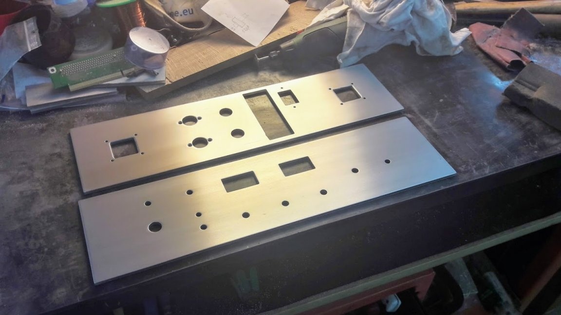
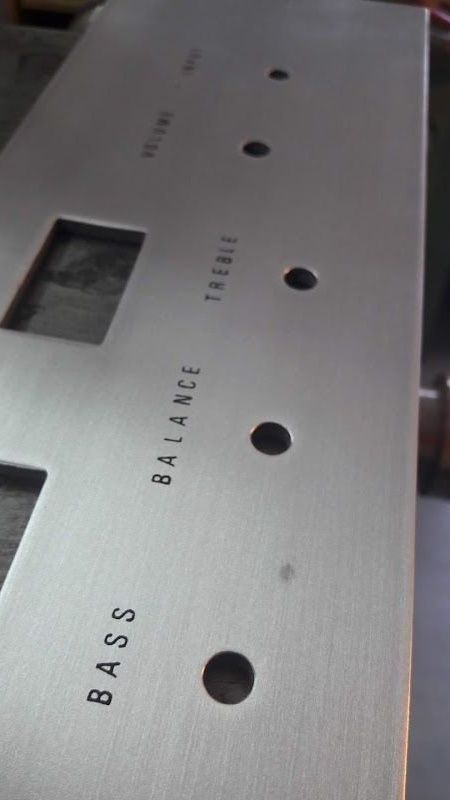
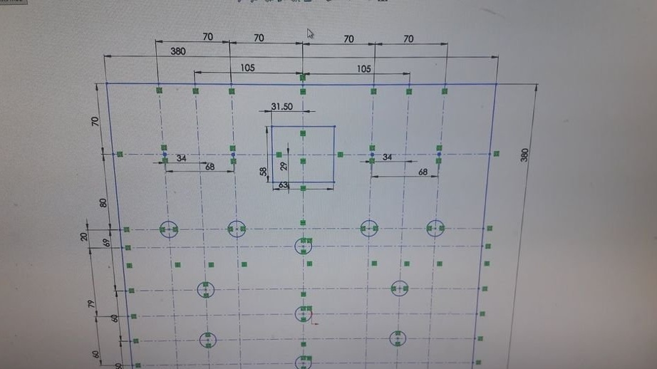
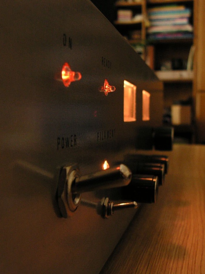
The front and back panels were designed in SolidWorks to see what the amplifier looks like. After that, a drilling machine was used to make the necessary holes for the connectors, fuses, switches, potentiometers and volume meters. Fine sandpaper is used for a good surface finish. After that, transfer foil for label printing was used, which was coated with a layer of shiny and transparent coating to prevent letters from erasing over time.

First, the upper panel was installed for a test landing, and then the necessary holes were drilled.

Step Five: Amplifier Wiring


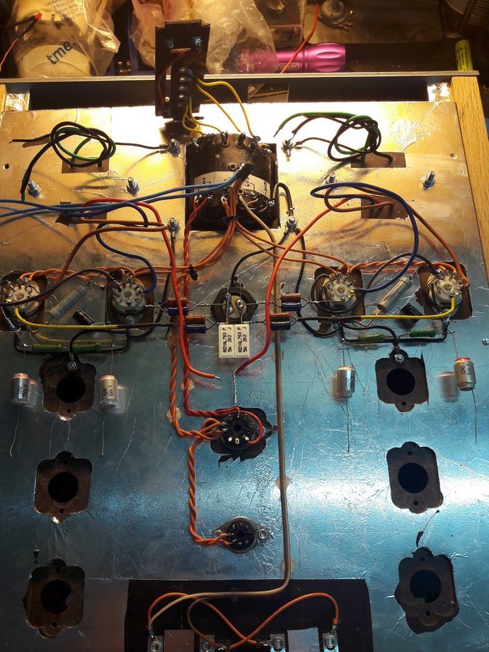
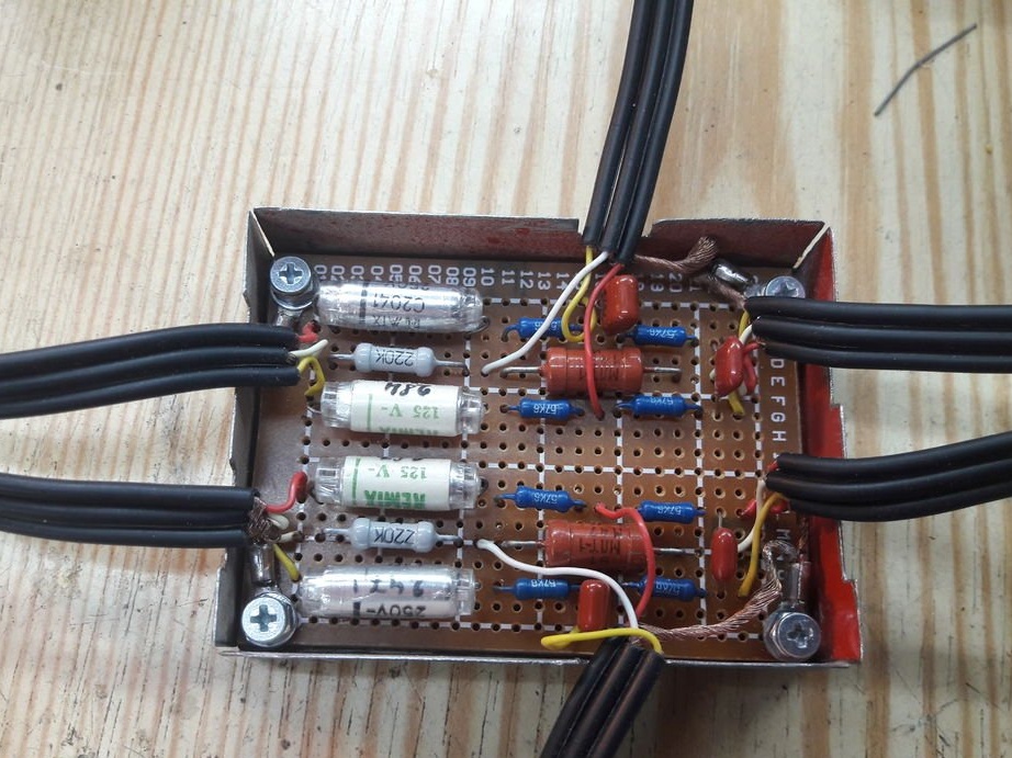
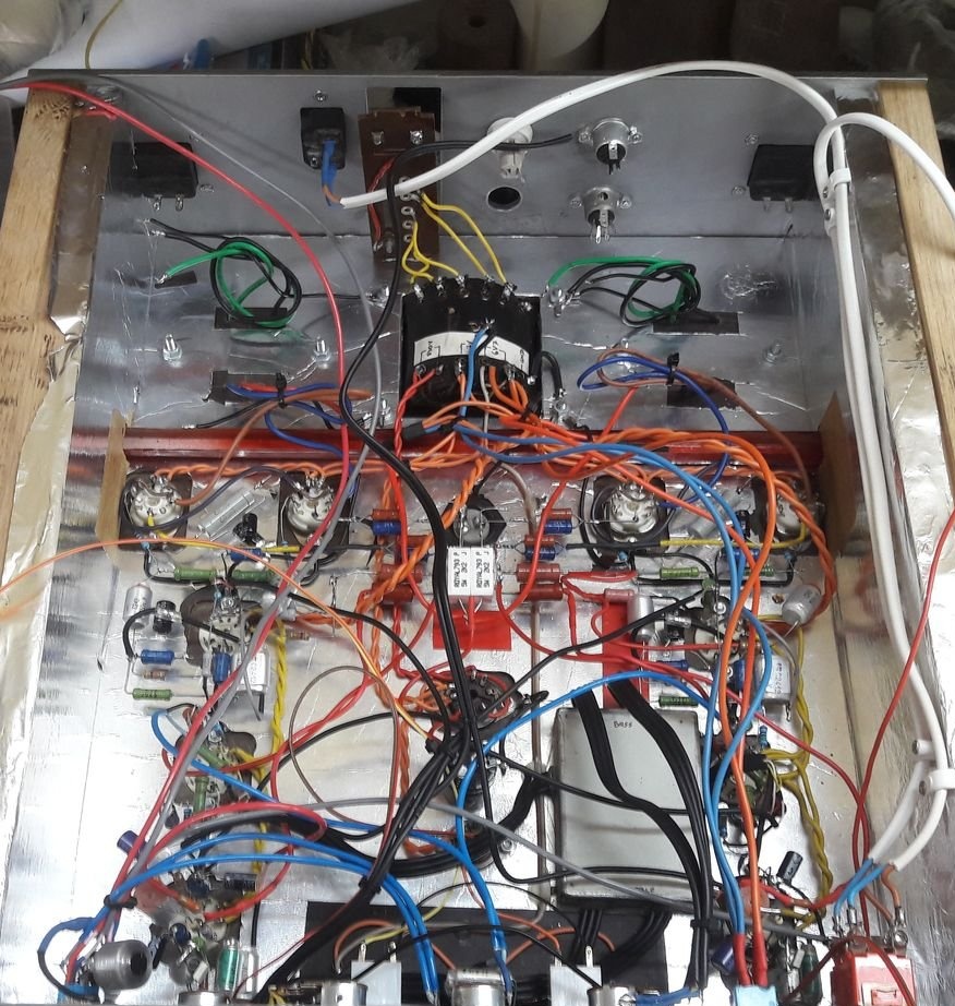
In order for the top panel to withstand transformers, the structure was reinforced with sheet metal. After that, wiring was started. This is the most time consuming procedure. First, the bolts are attached to the transformers and pipes, and then the necessary components are soldered. The tone control module needed additional shielding because it picked up noise from the environment. Therefore, it was installed in a metal box.

Step Six: Final Assembly, Problems, and Specifications


Thus, everything was collected. After the test, it turned out that the main power transformer had problems with a very high current, it was very hot. After about 30 minutes, he reached temperatures above 90 C. This was above his optimum working temperature. Even after installing a small fan inside the case, it did not work to lower the temperature. Therefore, I had to install another 6.3V transformer inside the case. This solved the heat problem of the main transformer.

Another problem was the very high noise level. This is likely due to ground loops that were accidentally left in the circuit.
Therefore, the inevitable modernization of this amplifier.

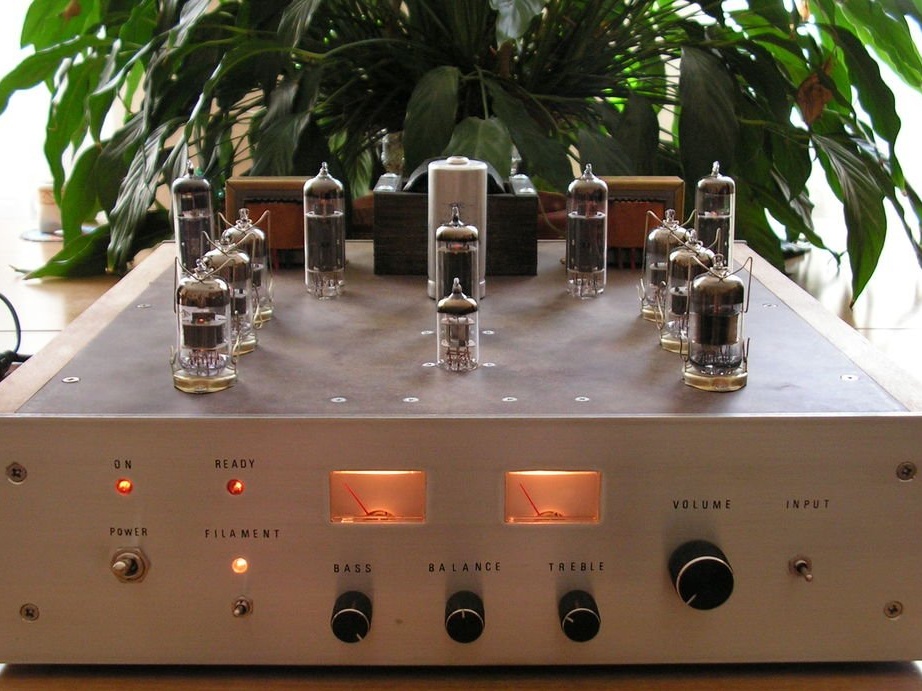
In the end, despite the small flaws of this amplifier, according to the author, it sounds great!

This amplifier can deliver a RMS value of 15 watts per channel without any noticeable distortion. It consumes about 10-15 watts from the network when idling and about 100 watts when operating at full power, transformers.
7.4
7
6.2

Add a comment

    • smilesmilesxaxaokdontknowyahoonea
      bossscratchfoolyesyes-yesaggressivesecret
      sorrydancedance2dance3pardonhelpdrinks
      stopfriendsgoodgoodgoodwhistleswoontongue
      smokeclappingcraydeclarederisivedon-t_mentiondownload
      heatirefullaugh1mdameetingmoskingnegative
      not_ipopcornpunishreadscarescaressearch
      tauntthank_youthisto_clueumnikacuteagree
      badbeeeblack_eyeblum3blushboastboredom
      censoredpleasantrysecret2threatenvictoryyusun_bespectacled
      shokrespektlolprevedwelcomekrutoyya_za
      ya_dobryihelperne_huliganne_othodifludbanclose
19 comments
Hands would be torn off at the most ... do not spoil for such a "construction" It is impossible to look at the installation without tears, the silovik and the input lamps without screens, the filament circuits of the lamps are made incorrectly (judging by the circuit diagram). I would also change the circuit of the output stage = - I would refuse auto-shift and make an adjustable shift of the output lamps to set the optimal working point. In general, there is a three-point scale on a five-point scale. Yes, and the exit indicators here would be lamp-like 6E1P for example. Here's something like that, for starters.
Valery
LED ... It shines ...
Firefly (or rotten) he shines ...
So, it can be called a bulb .... A lamp ...
And also the Sun, not only shines, but also warms - a heating radiator! The radiolamp heats up, the glow glows - the Sun! xaxa
Reflections .....
LED ... It shines ... It is installed in flashlights ... So, it can be called a bulb .... Lamp ...
Semiconductor lamp, so to speak ....))))
What !!!
Pleased: ... several old lamps were found. ... Other semiconductors in this homemade product were not used in principle ...
It seems that this is now such a fashion, a kind of foppiness - like calling a radio tube a pipe or a variable resistor with a reobass. From transcriptional and thoughtless translation. Somehow I met the description of the decoder chip, the domestic ID, in Russian, where she was called the "manager". Yes, and a separate circus with horses, this is when technical texts are written by people who do not understand anything, especially young ladies. ABOUT! This is something! It seems - "... knock it with a hammer a little."

Pulling the guts to the top panel is such a style, but only the guts should be aesthetic, yes. The top panel should not be so heated. Sockets are really, unreasonably different. In terms of installation, in principle, a tube amplifier is more expensive, heavier, energy-consuming, more complicated and more gentle than an analogue software, especially a microcircuit. They take it to make for a good beautiful sound. And here, one of the main principles is minimalism. Each connection, soldering, this heterogeneity introduces small, but distortion. Slightly degrading signal. When the count of soldering in signal circuits (and in a single-cycle cascade and power is a signal circuit) is hundreds, it is clearly audible through any decent speakers. The tube amplifier in this sense is very advantageous - UMZCH can consist of only one cascade, but usually two. To apply mounting on printed circuit boards or on mounting boards, this is a discrediting idea in principle. Profanity and only - anyhow beautifully glowed in the dark. This also includes tone controls, although options are possible here.
The words "shook the power transformer but failed" - baby talk! A tube amplifier is, first of all, very well-calculated and wound transformers, the simplest of which is network. The network background very often managed to defeat the artificial midpoint between the legs of the incandescent lamps. Resistors 0.5 ... 1 W, 100 ... 200 Ohms. Connect them to the common wire bus. They are mounted directly on the petals of the panel. Well, the land layout of course, as colleagues have said.
Well, you know, the man tried, he made the case at last. Already well done. Well, the full development of instrumentation is a fair task. This is a lot of work, few lovers own it fully, although of course you need to strive.
Wal
And can you read more how the inscriptions on the front panel were made?
if the inscriptions are in a foreign language?
Do you prefer the Old Slavonic inscriptions?
without reasonable and competent calculations
And here from here in more detail please.
as if a first-grader from a distant remote village built this miracle
And what, in fact, could you have done in the first grade? Actually, we listen to the sound with our ears. Here's what I agree with:
in the first cascades it is still desirable to shield the lamp
smile
Guest Sergey
But what, this craft is made in the export version, if the inscriptions are in a foreign language? Fragments of the circuit diagram are drawn incorrectly, and my doubt is about the operability of the design with the indicated values ​​of the passive elements. In the photo, the amplifier looks beautiful until the dust settles on it. But in general, frankly, this is an amateur radio HELP with careless installation, unjustified overall dimensions and a sloppy one without reasonable and competent calculations. It’s a shame to put it on public display even as an experimental mock-up option. Regarding lamp panels with a clip, this is not superfluous, even if the lamps are installed vertically. And in the first cascades it is still desirable to shield the lamp. The impression of what he saw is as if a first-grader from a distant remote village built this miracle, a short long winter evening in a barn or in a closet - then he is excusable. A large number of Russian literature was published on the topic of design, with calculations and illustrative examples of photographs. And here it’s as if the product of the Nizhny Novgorod radio laboratory from 1918. It's my personal opinion.
Quote: Korolev
judging by photo number 2, grandparents are clearly not foreigners!

Yes, the Soviet lamps. But this photo is only for the "red words". Lamp 6D14P - damping diode. It was used exclusively in television receivers in horizontal units.
The designation of the lamps in the diagram is not Soviet or Russian. We always had a “balloon” in the lamp. Variable resistors are also "foreign". "Mass" was painted just a line. So designated radio elements in Bulgaria, Czechoslovakia, East Germany.
In such constructions, the noise level often depended on the position of the mass points. Slightly moved, and the noise decreased, or even completely disappeared.
Maybe I'm wrong, but judging by photo number 2, grandparents are clearly not foreigners!

I read the name of the lamp (6D14P), and, suddenly, a joke from my childhood came up in my memory .... We asked if anyone had a PeI - Three - DeA lamp? ... And that was very funny! xaxa
And how will it sound from the Aglitsky "Babu - with a cart, a mare - in a pose!"
"If I had a horse, it would be a number, if a horse had me, I probably would have died! smile
And an overly ward child usually needs the services of an optometrist! smiles

P.S .:
"a woman with a cart - the mare is easier"

And how will it sound from the Aglitsky "Babu - with a cart, a mare - in a pose!" ))))))))))
Here it is auto-translation, "meaningless and merciless"
Remember the old joke: what will it mean to say “a woman with a cart is easier” after translating into English and back into Russian? "The lady leaving the car increases its speed!" smile
Another problem was the very high noise level.
And who will set the lamp operation modes? smile
There he is auto translation, "senseless and merciless"
Maybe I'm wrong, but judging by photo number 2, grandparents are clearly not foreigners!
In the box, in the house of grandparents, several old lamps were found
smile
Pulling out trances on the upper panel may be justified in the case of a thin body, but here there is where to roam, you could cram everything inside. And it is not clear why some of the lamps are installed with clamps, which are needed with a horizontal arrangement of lamps.
First, bolts are attached to the transformers and nozzles,
Here is the auto-translation, "meaningless and merciless." )))
Another problem was very high noise level. ... despite the small flaws of this amplifier, according to the author, he It sounds perfect!
What is it like?
... designed and built from the ground up.

Built - I believe. Designed - complete nonsense. These are typical wiring diagrams. Such in bulk in any literature 1970-1990.
... a project, and it took a lot of time and patience ...

Probably, most of the time and patience was spent searching for this scheme.
I wonder what prompted the author to pull out all the "guts" on the upper panel? Okay lamp. They look mysteriously beautiful for the current generation. But why pull out the transformers?
The project can be rated solid 3.
I liked the panel. goodgood

We advise you to read:

Hand it for the smartphone ...