We offer you the option of manufacturing a doorbell with increased power and a certain duration of musical sound. The duration of the signal is determined by the setting and does not depend on the time the call button is held. The sound volume is manually adjusted to an acceptable level, as well as the duration of the sound.
Based on the cost-effectiveness and compactness of the design, the proposed call design does not require the use of any batteries and is built on the basis of a network transformer-free power source. In normal condition, the call is completely disconnected from the network. When the button is pressed, the ringer sounds and the built-in time-adjustable timer. After the set time has passed, the sound ends and the device is disconnected from the network.
At the heart of the device is a chip with one or more tunes wired into memory. Based on this chip - a musical synthesizer, we will make a simple music call using the following scheme.
Doorbell diagram
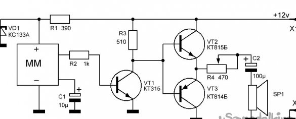
The ringer circuit includes a music module (MM), an audio frequency amplifier (RF) on transistor VT1 and a power amplifier on transistors VT2, VT3 implemented in a push-pull circuit.
From the conclusions of the MM microcircuit, the signal through the resistor R2 and capacitor C1 is fed to the amplifier of the AF call. The sound volume of the speaker SP1 set variable resistor R4. A description of the operation of the music module and preparation for it is given in the description “Doorbell from a musical toy».
The transistors indicated in the diagram can be replaced with imported analogues. Loudspeaker SP1 can be 1 ... 2 W, for example, 1GD40, 2GD36 with a coil resistance of 8 ... 10 Ohms.
Work above homemade A “doorbell from a musical toy” appealed to consumers, but several comments and suggestions were made.
1. The volume of the ringer is not enough. Its sound is not always heard in other rooms when the TV or radio is turned on. This problem is solved in the diagram above, by changing the amplifier of the RF signal of a home call - by introducing a power amplifier in a push-pull circuit.
2. A short signal, when you briefly press the call button, is not always heard due to the surrounding background. Requires a longer sound duration. This wish can be implemented by introducing into the design of the delay unit (timer) the disconnection of the apartment call.One of the simple options for such a timer is proposed to be made according to the following scheme.
Timer and power supply circuit
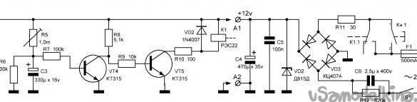
The timer circuit consists of a delay unit for transistors VT4, VT5 and an executive relay K1, as well as a power supply for the entire structure of the apartment bell. To turn on the device, the call is connected to the timer through the connector X1-X2.
Since the energy requirement of this design is negligible (160 ... 180 mA), a transformerless power supply can be used for it. Alternating voltage is supplied to a half-wave rectifier made on the diode bridge VD3. The rectified voltage is slightly reduced and is set using the Zener diode VD2 at the level of 12 volts. Next, with an electrolytic capacitor C4, the voltage is filtered and used to power the device. Ceramic capacitor C5 is used to eliminate high-frequency interference, and resistor R11 is used to smooth the current surge when the bell is turned on.
The device starts to work only after pressing the bell button Kn1. Since in the absence of power, the capacitor C3 is discharged through the resistor R6, when the power is applied, the capacitor C3 begins to be charged through the tuning resistor R5, which regulates the charge speed. In the process of charging the capacitor, the transistor VT4 is closed, and VT5 is open. Therefore, the melody will immediately sound, because Relay K1 will work and contacts K1.1 will shorten the contacts of the button Kn1 for the time set during setup. As a result, a quick shutdown of the button will not affect the duration of the sound. After some time, the capacitor will be charged to the opening voltage of the transistor VT4. VT5 will close, the relay will turn off and its contacts K1.1 will disconnect the device from the power supply, the melody will stop playing.
For capacitor C6, which suppresses excess voltage, it is better to use capacitor K73-17 with an operating voltage of at least 400 volts. The capacity of this capacitor can be assembled from capacitors of a smaller capacity.
In the call, you can apply other relays with a supply voltage of the winding 10 ... 12 volts, with a contact group, designed for 220 ... 250 volts and a current of 300 ... 500 mA.
Making a call comes down to setting the desired duration of the melody by adjusting or selecting the resistor R5.
Production of a music unit and amplifier
1. Choice of housing
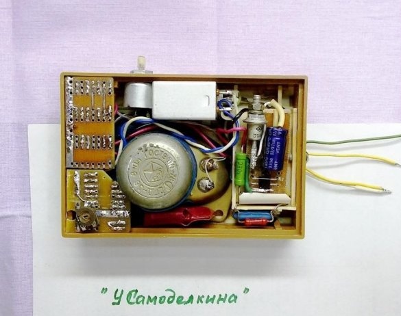
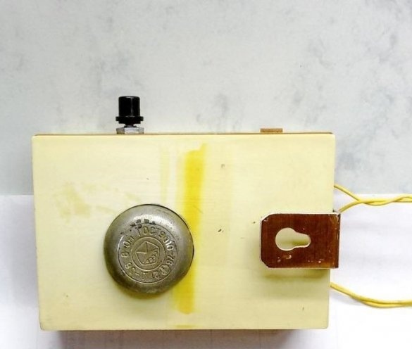
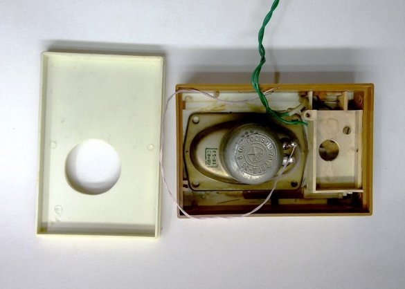
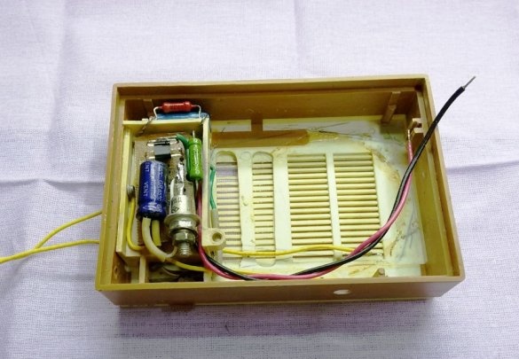
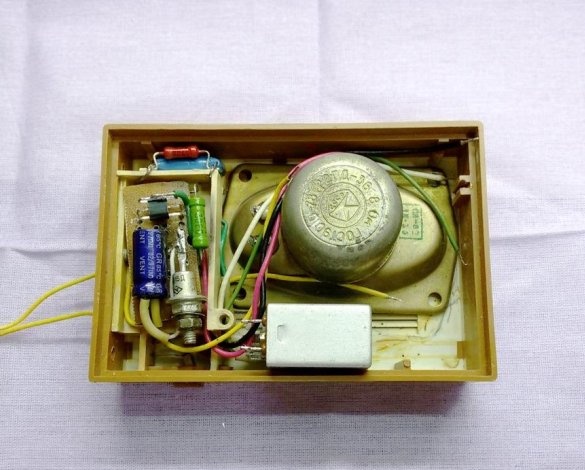
This device uses a case from the children's kit for the assembly of the Malchish radio receiver measuring 110 x 75 x 33 mm. Also from the kit, a battery compartment is used, with a power switch built in there. The existing speaker has been replaced with a more powerful one. It is also possible to apply for homemade and subscriber broadcast loudspeaker or intercom. And the speaker located there should be used in the design.
2. Equipment
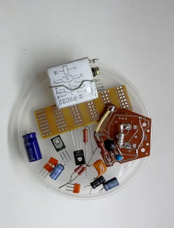
We complete the device with radioelements, according to the schemes.
3. Music module
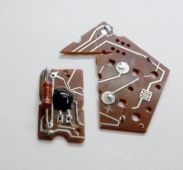
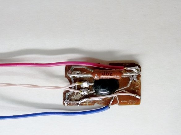
In this version of the manufactured bell, we use a musical synthesizer found in a broken musical toy. It is a multi-pin open-circuit microcircuit. Two of them, this is the power supply of the microcircuit, they are easy to identify, since they are connected to a power source. The other two outputs are connected to a miniature sound-emitting head or a piezoelectric sound emitter. These conclusions will be used.
4. Finalization of the music module
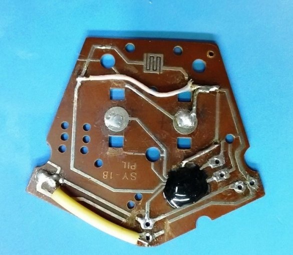
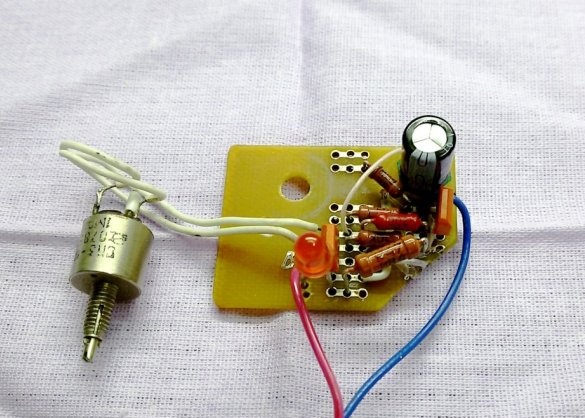
In this design option, we are only interested in the microcircuit. Tight installation of the call scheme in the free space of such a board is not possible. Therefore, we cut out part of the board with the microcircuit and supplement it with the accompanying parts of the music module. This is the current-limiting resistance R1 and the Zener diode VD1 to the power supply voltage of the module 1.3 volts.
5. Making a call
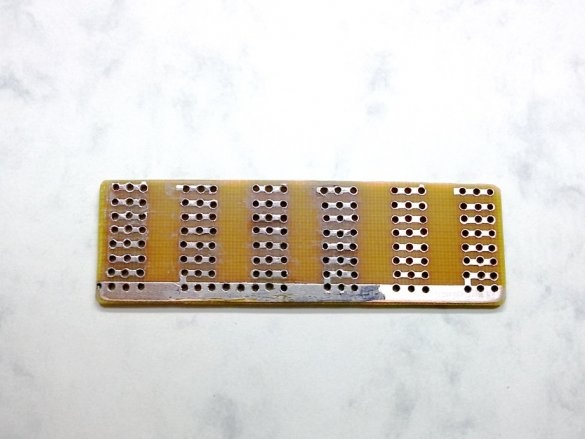
We select or manufacture (based on the internal dimensions of the case) a board for a call, we perform installation and soldering of parts on the board, guided by the device diagram.
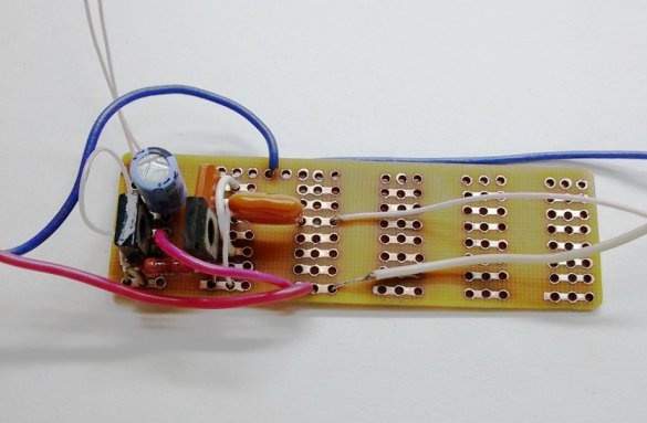
6. Build call elements
We electrically connect the ringer board to the music synthesizer board. We connect the combined design to the 12 volt power supply and check the call in operation. If necessary (poor sound quality, low volume), we select the value of the resistor R3.
7. Power Supply Fabrication
For the manufacture of a network power supply, we use the battery compartment of the receiver with a power switch.
We collect the quenching capacitor C6 from three, connecting them in parallel, place the capacitors under the plastic compartment. On the board located in the recess under the battery, we mount the rest (low voltage) part of the power supply. Thus, the entire power supply will be placed in the dimensions of the battery compartment (under the “Crown”) compartment, and the high-voltage part (220 volts) will be guaranteed to be protected from the outside and from the rest of the internal part of the device. We mount the power supply unit together, install and fix it in the device case. Install in place in the case, loudspeaker and relay.
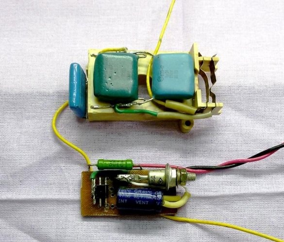
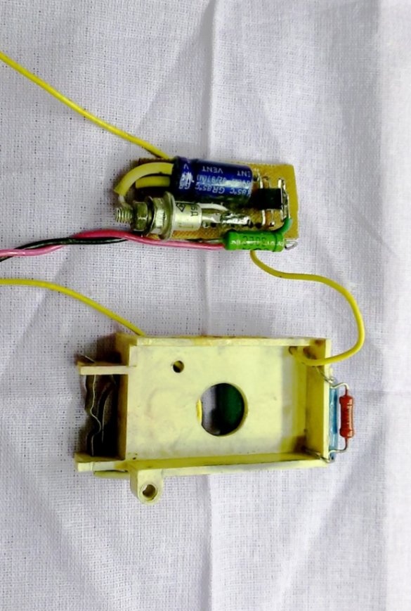
8. Timer Making
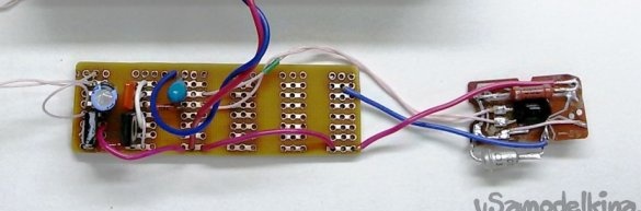
The timer is directly connected to the power supply and controls its operation using a relay. We select or manufacture (in accordance with the remaining free, internal dimensions of the case) a board for mounting the timer, unsolder the parts on it in accordance with the diagram. The LED is set temporarily for visual control over the work when debugging the circuit.
To adjust the duration of the ringing, temporarily replace the R5 trimmer with a 1 mΩ resistor. The next time you select the optimal duration of the sound, you can measure the actual resistance of this resistor and replace it with a constant resistor of slightly lower resistance. To adjust the duration of the sound, connect a trimming resistor in series with the installed one, but with a smaller resistance and size. This is done in the presented design (pictured below).
9. Assembly
We collect a musical call into the case, connect the device to a 220 volt network and use the button to check the call in operation.