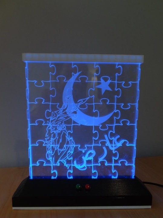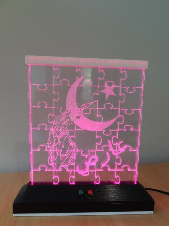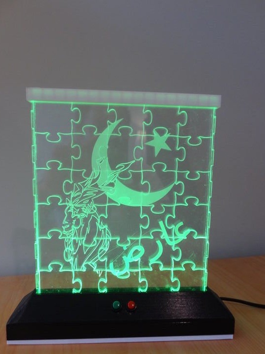

The author of this lamp has always liked various acrylic, laser-cut night lights, which others did. He decided to do something of his own, unlike anything else. Thus, the idea was born to design a mosaic that fits in a thin box, and then will be illuminated with an LED strip.
As for the actual lighting, there was a desire to make the LEDs slowly switch between ranges of colors, so that it was possible to either pause in a certain color or switch to a new color.
Materials used:
Two different colors of 3D threads
Spray paint
Skin
Screws: M3 10mm
Capacitor: 1000 uF 6.3 V
Round mini reset button (one red and one green)
Tumbler switch
RGB LED Strip
Arduino Nano v3
Power connector
A step-down transformer
12V power supply
Instruments:
Soldering iron
multimeter
CO2 laser cutter
3D printer
Glue gun
Acrylic adhesive
Wire stripper
Drill
Drills (used to clean holes in the 3D model)
Software:
Inkscape
Librecad
Freecad
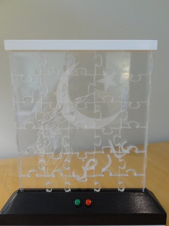
Step One: Preparing Puzzel Art Work


Since the acrylic puzzle will be cut using a CO2 laser, the file for it must be in SVG format.
Using the SVG Generator Wolfie, a basic puzzle map was created.
This puzzle lamp was created for a family from Pakistan, and therefore the lamp will have a Pakistani look.
Using the trace parameters in Inkscape, the necessary PNG files were converted to SVG and puzzles were added to the map.
The colors were set so that the base of the puzzle was cut out and parts of the image were engraved.
Attachments
Finalpuzzelsvg
Step Two: Making the Box
The luminaire was developed using LibreCAD and then exported to an SVG file. The file was then edited in Inkscape in order to set the correct color and thickness of the lines for cutting on a CO2 laser.
Using acrylic glue, the sides of the box were glued to only one of the larger sides. In fact, the puzzle can be built into the box. After gluing, the acrylic puzzle is held at rest with a white top cover and LED base.
Attachments
Case
Step Three: Printing the base and top cover

Using the FreeCAD software, the attached elements were designed and printed:
Top cover (white)
Base
Bottom cover (white)
For unknown reasons, the angles of the inclined sections of the base did not print very smoothly. Sanding did not result in a uniform finish on the substrate. Therefore, the base was sanded with fine sandpaper.
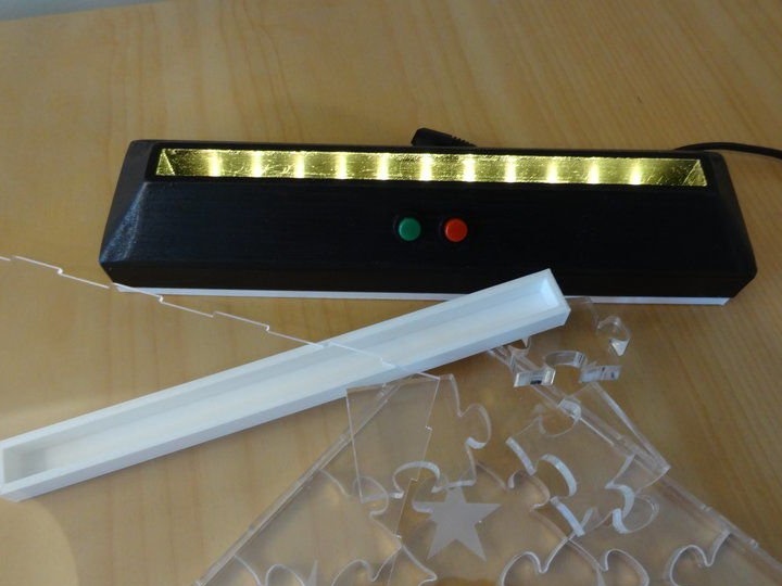
Then the RGB LED strip was glued so that the LEDs were facing the bottom of the puzzle. The sticky surface under the LED strip did not hold the strip properly, so I had to add some super-glue to fix it properly.
The reset buttons, switch, and power connector are in place or screwed on.
Attachments
Base4.1.2
Toprint-base
ToPrint-BaseCover
Toprint-top
Step Four: Arduino Programming and Testing Settings
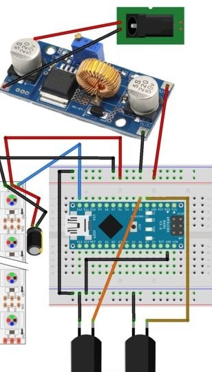
The Arduino circuit board has been connected and configured as shown in the figure above. Initially, there was no need to turn on the transformer or external power connector, since the board was powered and programmed via USB power connected to the computer.
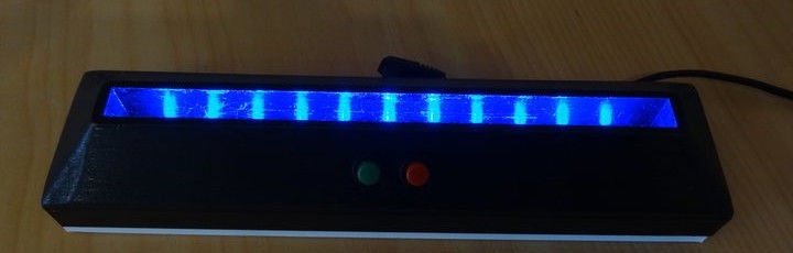
From the code (you can download from the link below) you will see that the LEDs will slowly switch from one color range to another. If button 3 (green) is pressed, the LEDs go to the next main color in the sequence. If you press button 2 (red), the LEDs stop changing and continue to display the current color. To continue observing the color change, the red button just needs to be pressed again. Pausing the display does not stop the program, so when the red button is pressed again, the LEDs will go to the current color through which the program works.
Then you need to connect everything and pack it in a box.
Attachments
Rainbow2-Final-NoEEPROM
Step Five: Assembling the luminaire as a whole
The author wanted to start the luminaire from a standard 12 V power supply. Since Nano can be powered from 6 to 20 V, you can simply connect the plug connector to the GND and VIN pins using the 5 V pin on the Nano to power the LEDs. However, this is not the case. In short, when using the Nano controller, the LED strip consumes too many amperes to be powered by the 5-volt Nano contact. Therefore, a step-down transformer was added, which fed the nano and the LED strip.
Since this design works very well when powered via USB, all this pain could have been avoided if the project had been designed so that the Nano could be located through a USB port that is accessible from the outside. Thus, the project could be powered using a standard USB cable connected to a USB charger.
Note: Arduino seems redundant for this project, which can also be controlled by one of the ATtiny controllers. In this case, a step-down transformer would be necessary.
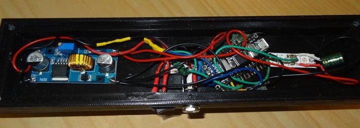
Using a glue gun, all components of the lamp were glued. The controller and transformer are located below.
When gluing, it is advisable to ensure that the glue is not located near any part that may heat up, as this will cause the glue to melt and the component to peel off during use.
When connecting the power connector to the chassis, you must use a multimeter to determine which terminal is positive and which is ground. A rocker switch is connected between the positive input of the transformer and the positive contact of the cylinder connector. This is not shown in the circuit diagram.
Before connecting anything to the output of the transformer, it must be connected to a power source, and then using the multimeter to adjust the output voltage setting (by turning the adjustment screw) until the voltage reaches 5 V. After installation, this screw is sealed with oil paint, so that it cannot be accidentally moved in the future.
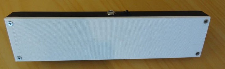
Now the bottom cover can be fixed and screwed.