
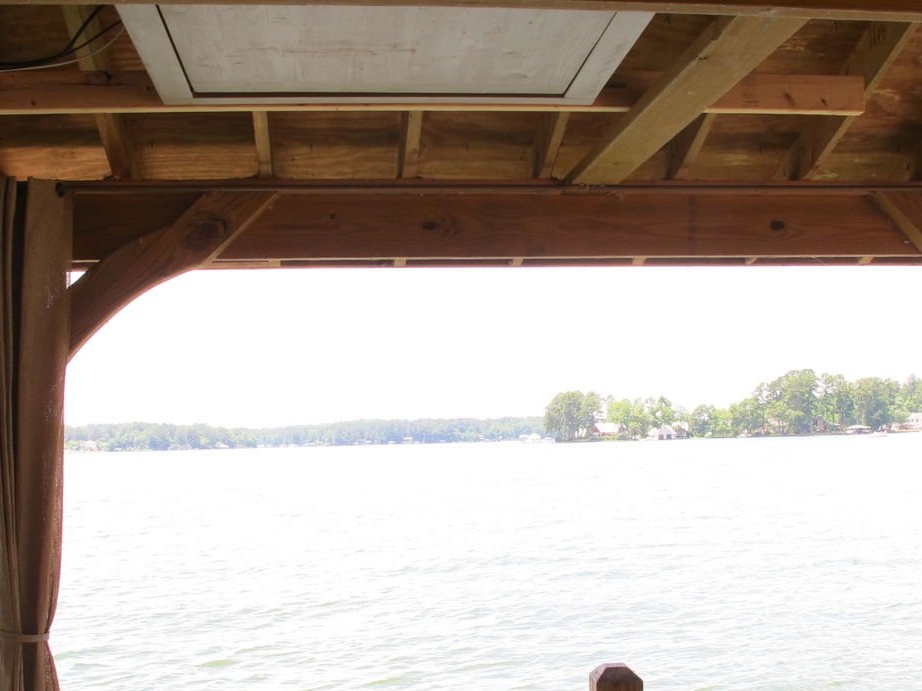
A hinged mount for a TV is cool, and the author has been looking for an opportunity for its implementation for a long time. It has a porch with a large covered area, which is ideal for relaxing while looking at the water. Since the roof of the veranda has a small angle, which does not allow you to mount a sliding type of TV mount, it is ideal for hinged mounting.
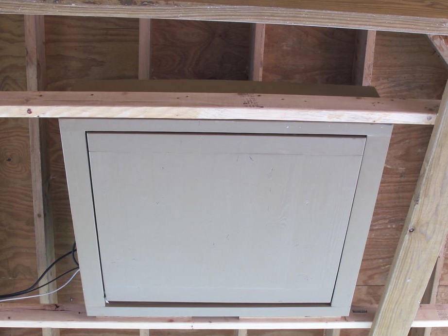
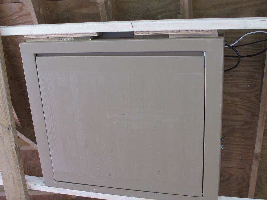
Television Lift: Closing
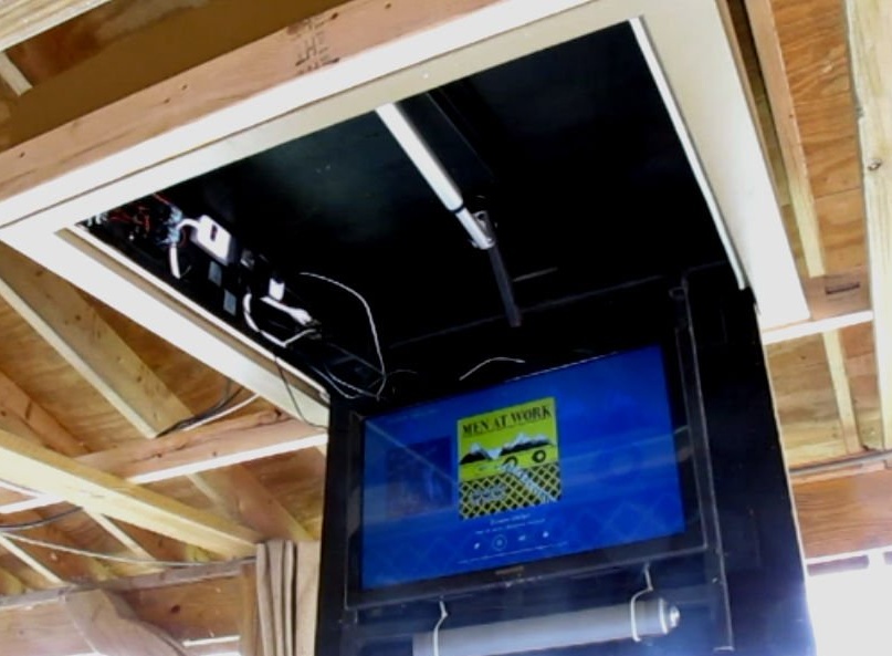
Television Lift: Opening
After searching for commercial offers on the market for such fasteners (thousands of dollars), it was decided to build their own fasteners.
Materials for the manufacture of:
20 mm. plywood
Pine or poplar board
2 bearings
steel rod
Limit switches
12 VDC linear drive current
Relay 12V DC
Extension
TV mount
Directional switch
12 VDC power supply Current 5 A
Magnetic reed switch
Connecting wire
Terminal block
Cable entry
Step 1: The Mechanism
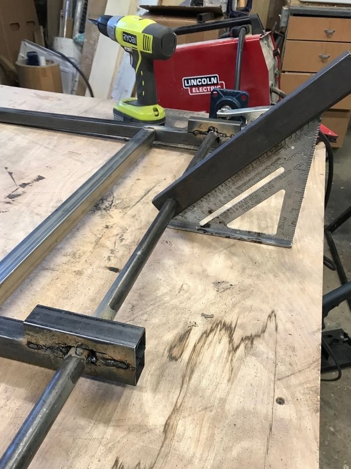
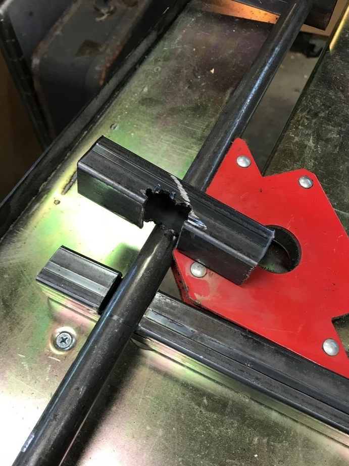
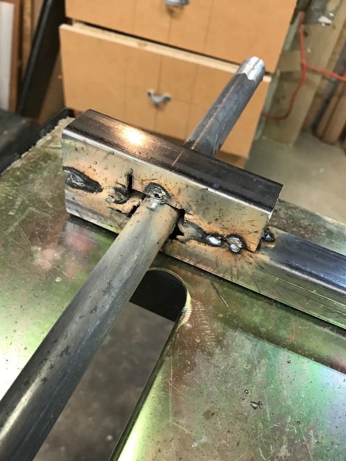
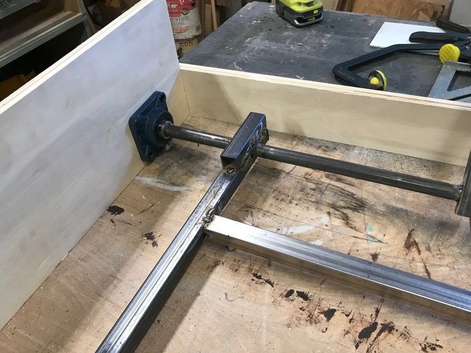
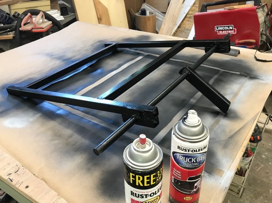
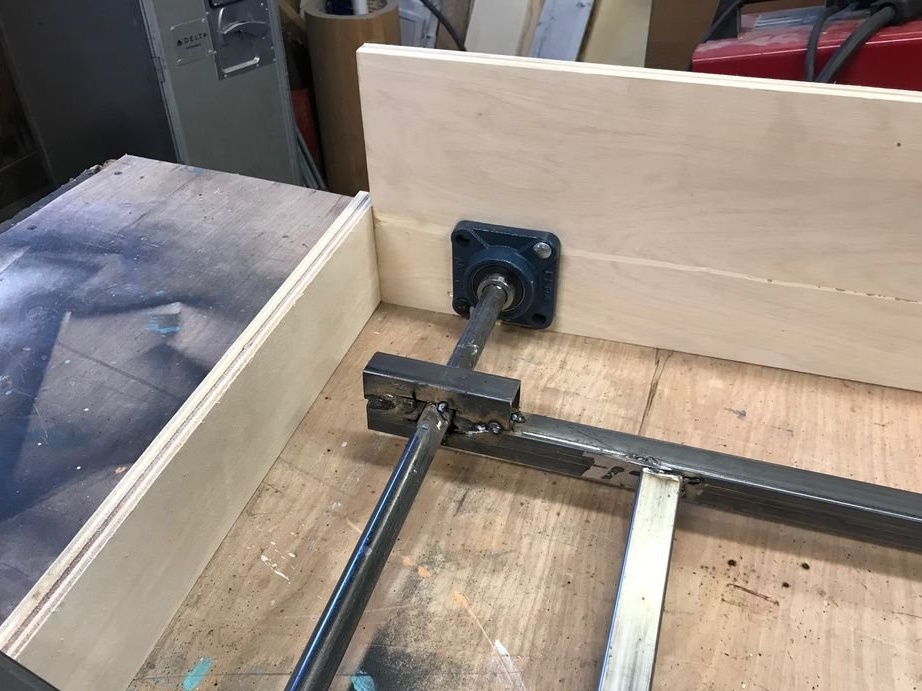
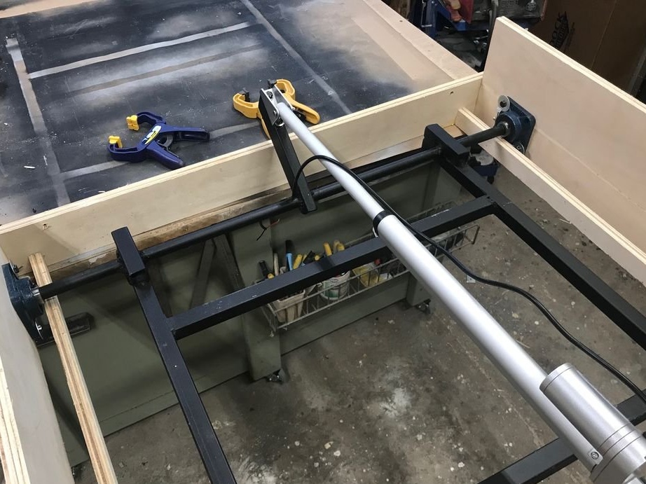
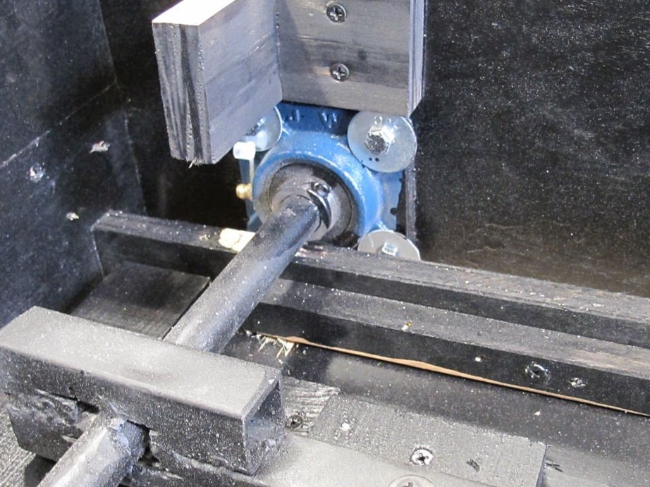
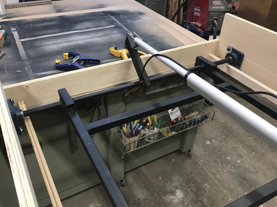
The work was started with a steel rod 90 cm long and 19 mm in diameter. First, a piece of 38mm steel tube was cut about 30 cm long, and then a hole was drilled for the rod. After the profile pipe was centered on the rod at an angle of 45 degrees and welded in place.
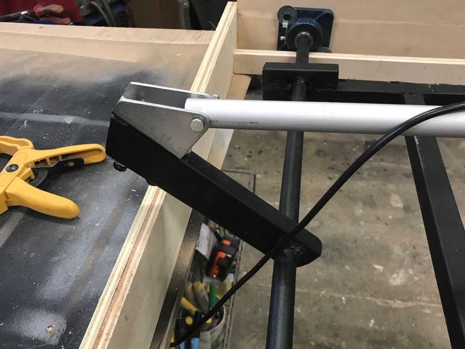
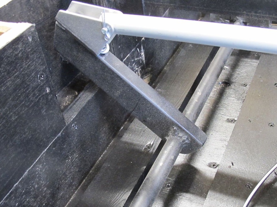
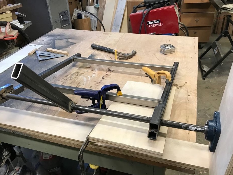
Then a frame for mounting a TV set of 25 mm steel tube was welded. Instead of trying to weld a flat pipe to a round rod, a section for the pipe was cut to install it. Then a similar smaller section was added to the top, and a pipe was inserted between them.
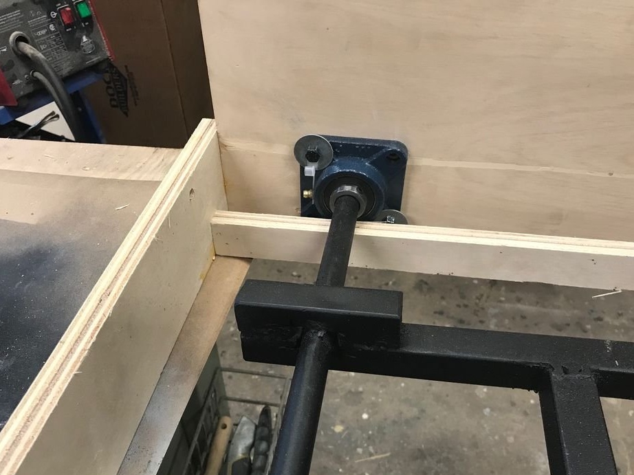
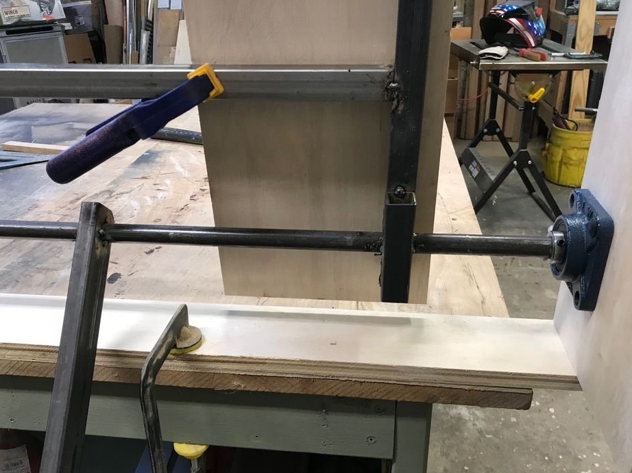
For the axis, thrust bearings were used.
Note: Since the stem rotates only a quarter of a turn, you could probably get by with a bronze bushing and a little grease.
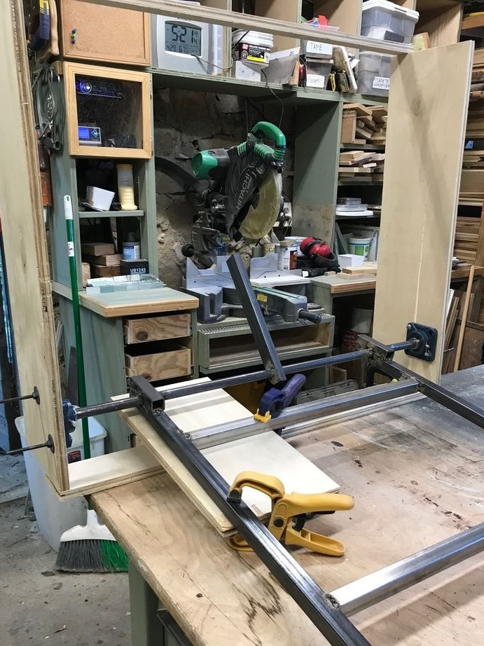
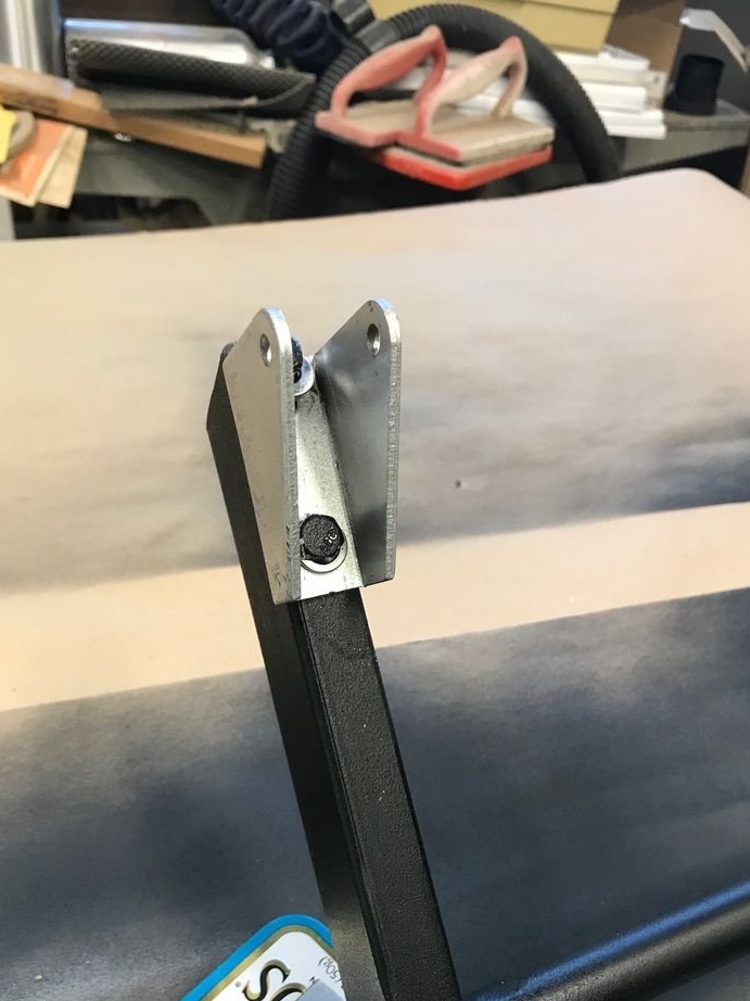
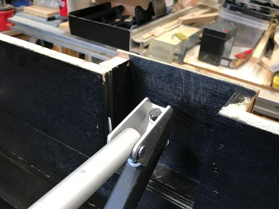
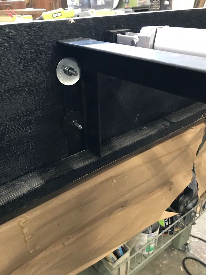
After checking the installation location of the drive, about ten cm were cut from the top of the pivot arm and a mounting bracket was installed.
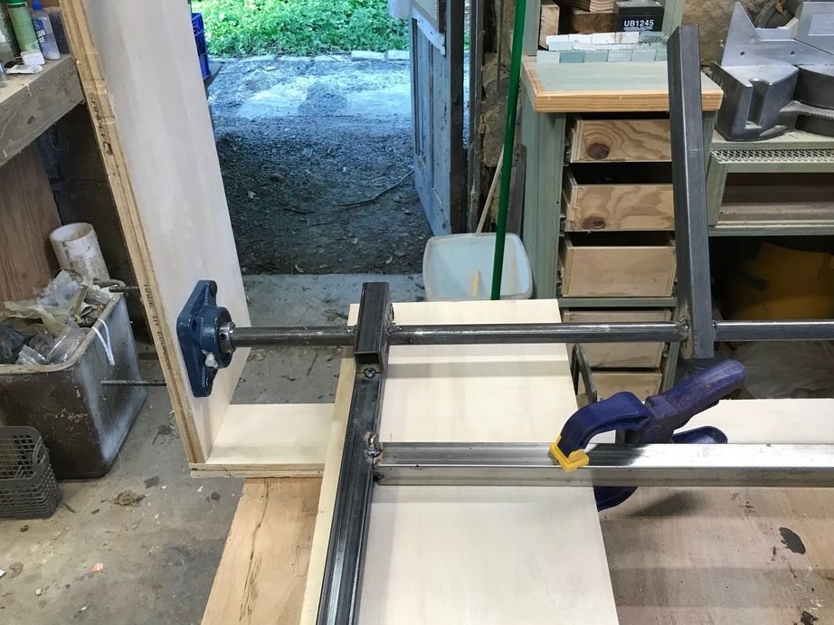
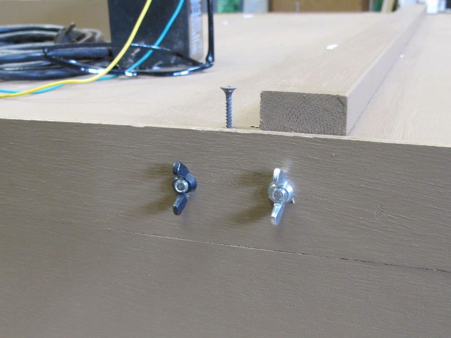
The finished mounting frame and bearings were then screwed onto the wooden case using hex bolts and flange nuts.
Step 2: Enclosure for the swing frame

This rotary TV was designed for casual viewing, so a large TV was not required. A 32-inch TV was chosen that would provide good viewing and would not be too expensive - since it is installed on the veranda.
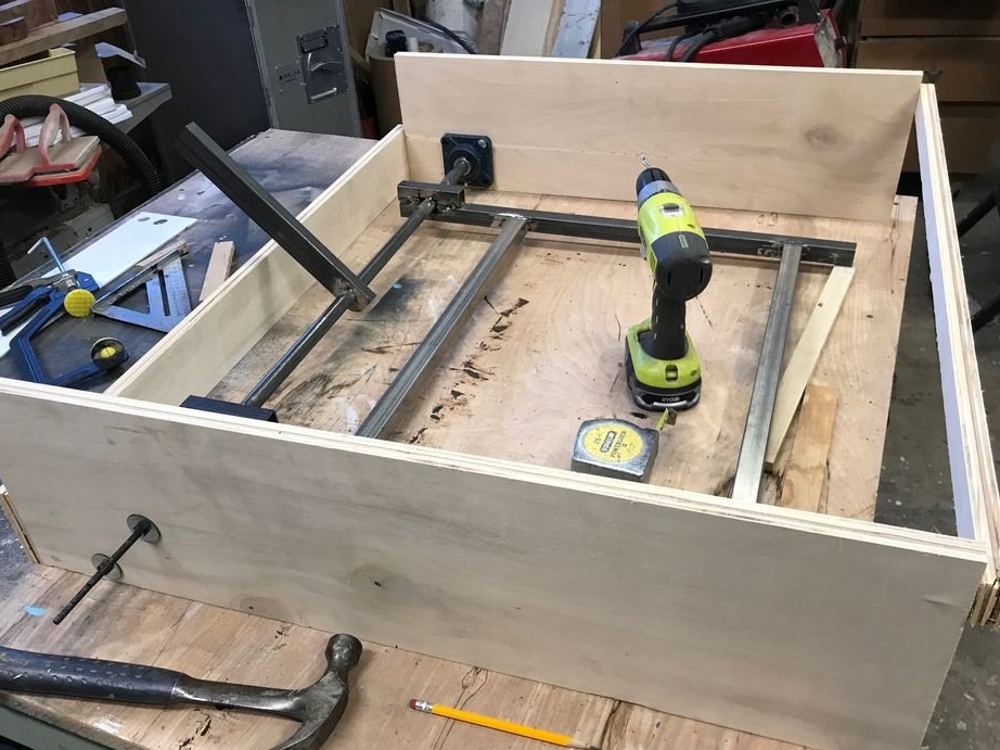
The case is made in the form of a box made of 19 mm case-type plywood, the dimensions of which are approximately 90 cm in width, 90 cm in depth and 23 cm in height. Some experiments with the size of the mechanism showed that more depth would be needed, but a higher box meant that it would fall on the slope of the roof rafters.
The compromise was to build a small “chipper” on top and behind the box, which would cover the pivot arm and slide between the rafters.
After installing and testing the mechanism (step 1), the master did not like how the body tilts when the elevator is removed. He added a piece of metal for stiffness, bolted to the front and back.
Step 3: Installation Details


Then pine strips were added to the bottom (the part that faces down) to give strength and create a frame for the panel that would cover the TV. The panel was made by gluing a pine beam. After installing the panel on a metal frame, it took a lot of trouble to choose the right size and position. This required a gap of about 3 mm in front and side and about 25 mm in the back to give it the correct shape.
As soon as the panel came up, it was removed and the inside of the case was painted black.
Step 4: Electric Filling
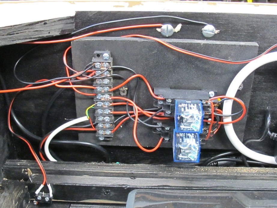
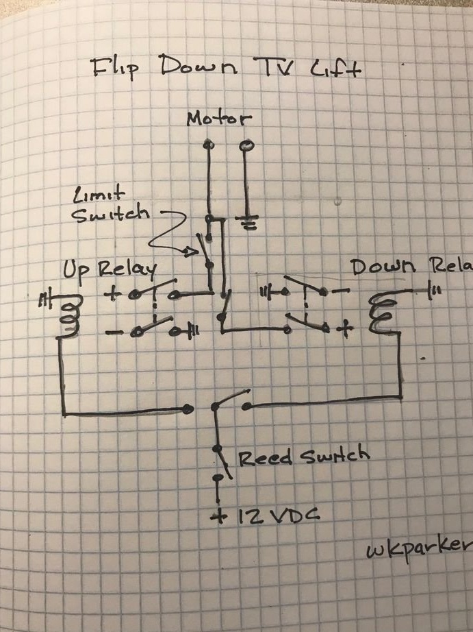
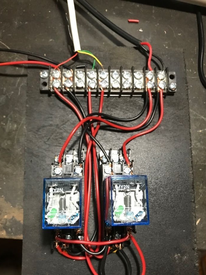
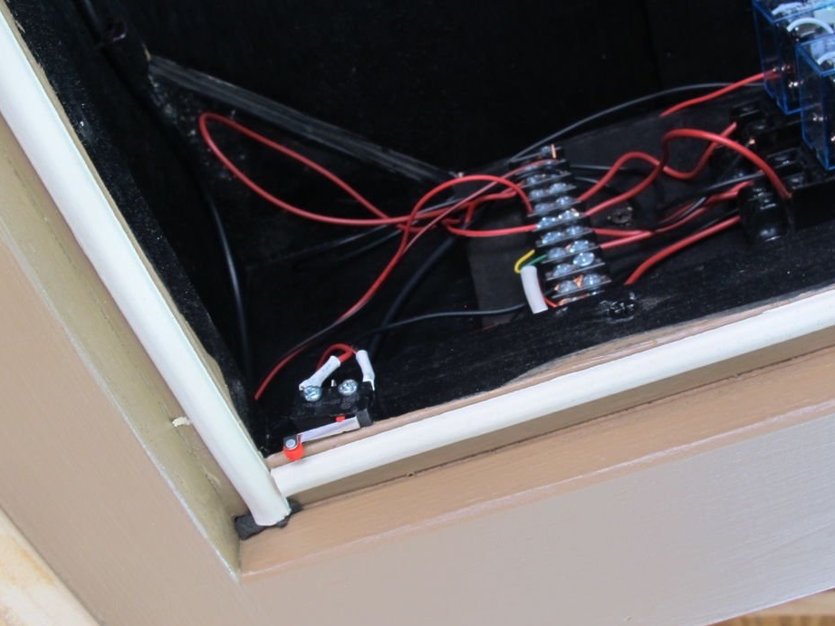
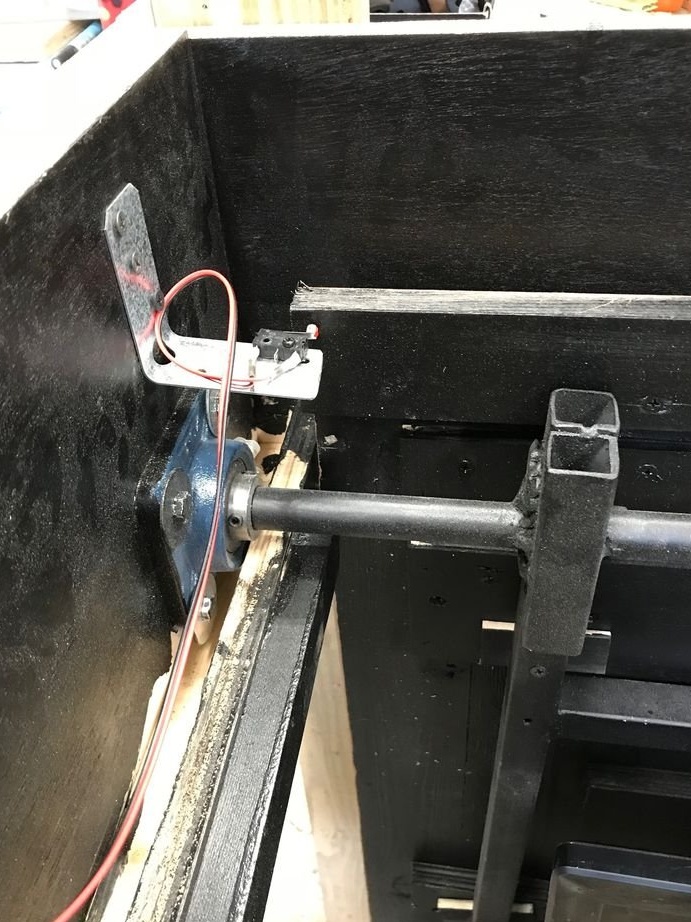
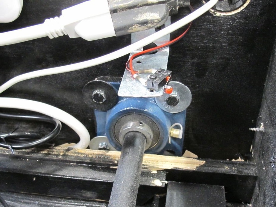
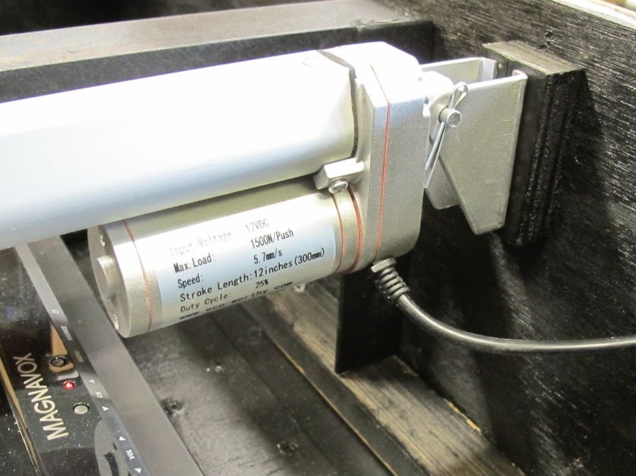
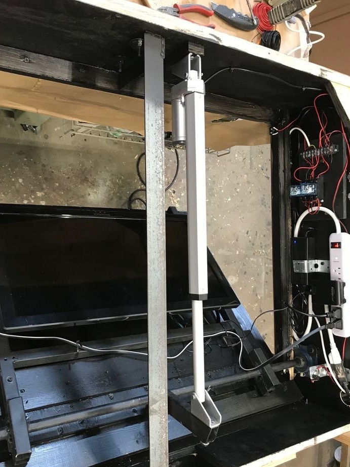
The mechanism is driven by a 12-inch linear drive, 12 V DC. current. Power is supplied from a DC source of 12 V, 5 A. The direction is controlled by a DPDT spring-loaded switch (using only half of the switch), which is installed at a distance of a couple of meters and connected via a 4-wire cable. The direction switch controls one of the 2 relays, both of which are connected to the motor. Since the direction switch is spring-loaded, there is no chance that both relays will be able to operate simultaneously. Two SPDT microswitches are installed to stop cap movement at the upper and lower boundaries.
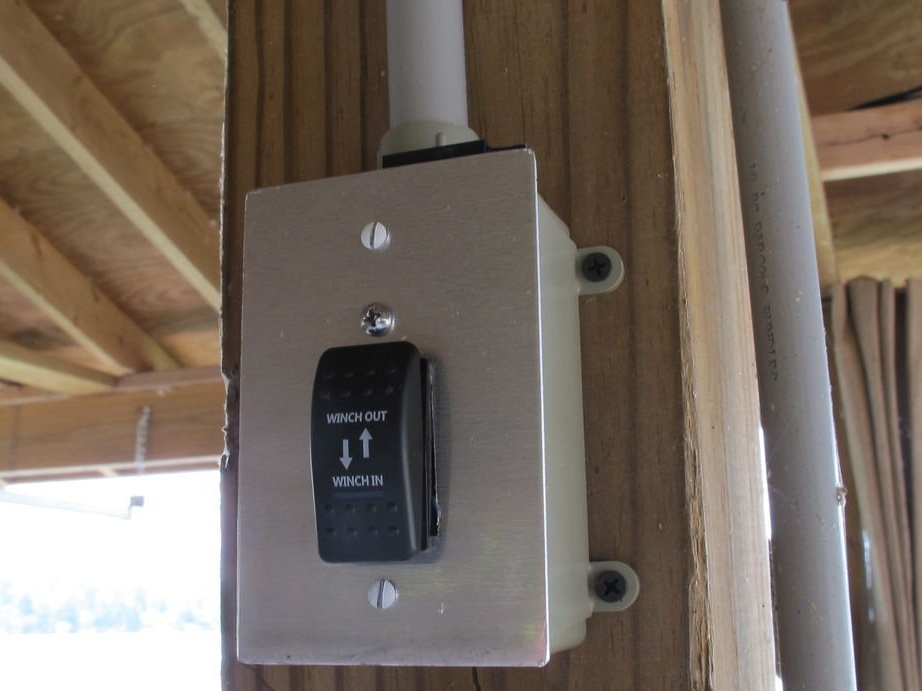
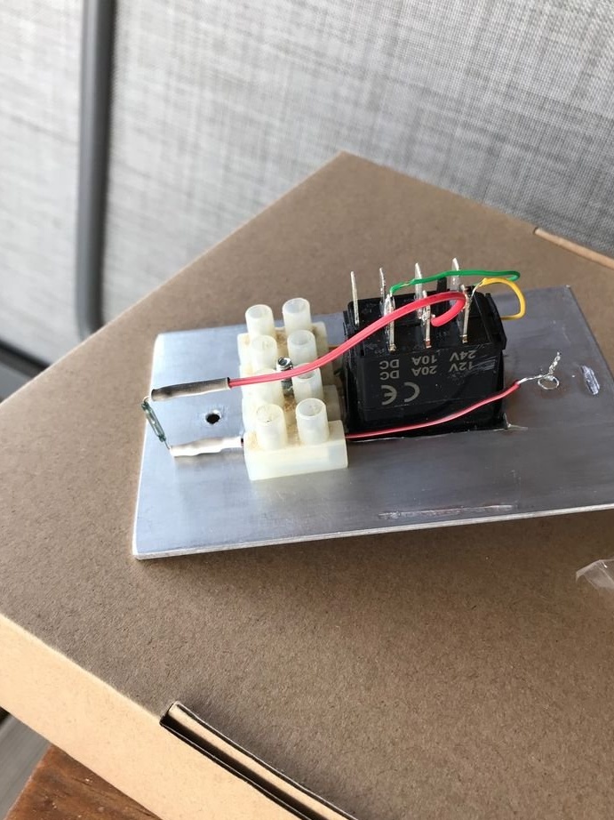
It was decided to firmly connect the direction switch, as the remote control is another thing that can be lost. It is mounted on a pole two meters from the TV. So that no one could control the mechanism without permission, a magnetic reed switch was added to the direction switch, which is located just below the top of the junction box. The holder for the small bar magnet and the frame were printed on a 3D printer. As soon as the “magnetic key” is installed, the switch works normally. If you delete it, nothing happens!
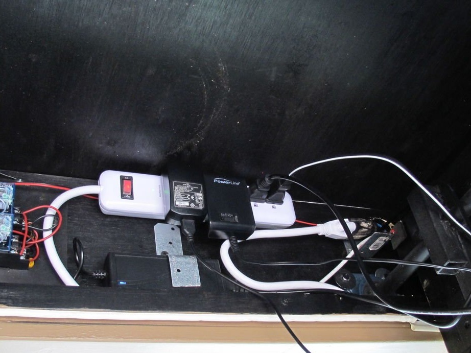
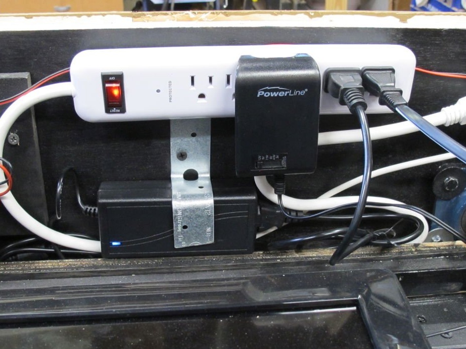
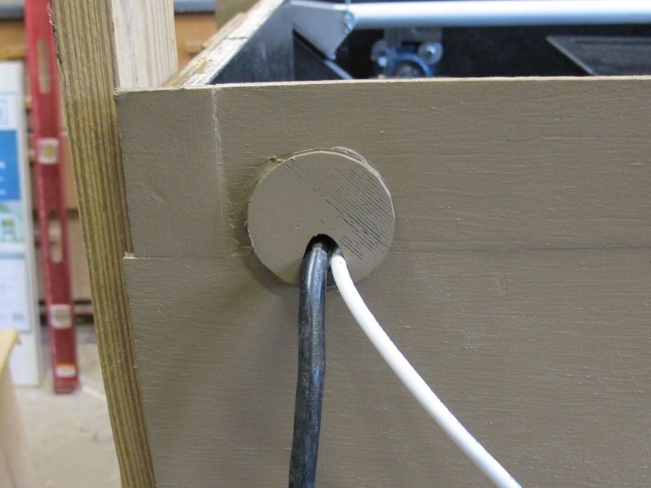
The width of the housing made it possible to install an extension cord and relay guides on one side. The terminal block helps keep wiring clean and safe. Power and Ethernet wiring runs through the cable entry on the side of the seat.
Attachments
Cable gland
Magnetic key holder
Step 5: Complete Installation
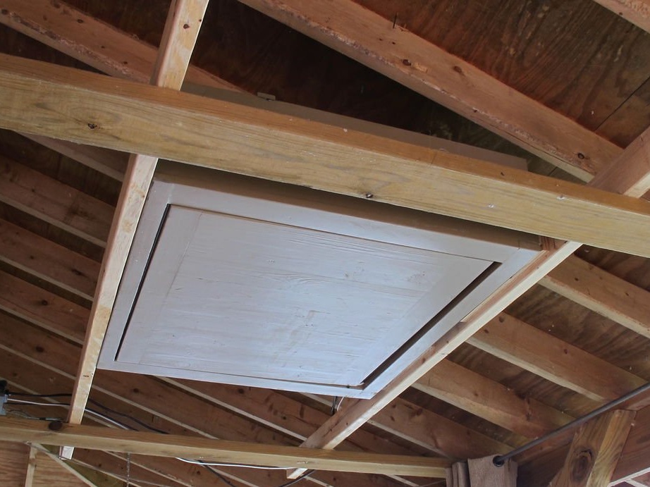
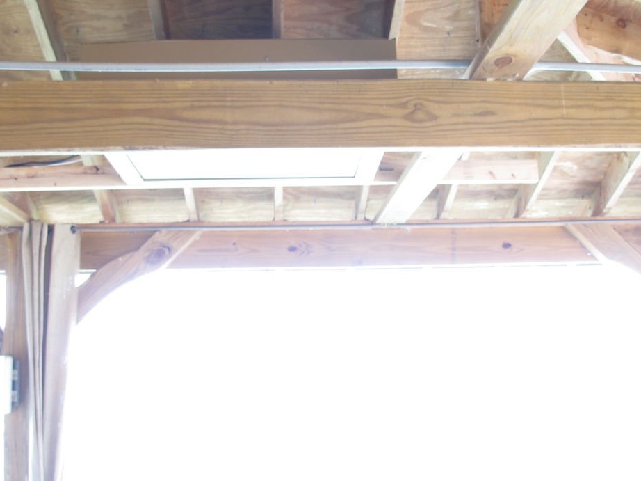
A TV is installed under the rafters of the veranda. Boards are attached to each side so that the supports rest on the frame. We shift the television to the position, adjusting it so that the "protrusions" for the rotation mechanism slide between the rafters. Once the final position is found, the ends of the boards are cut off.
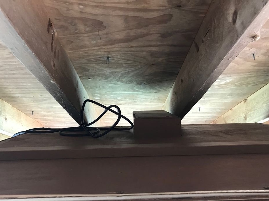
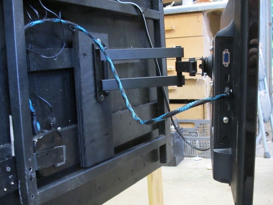
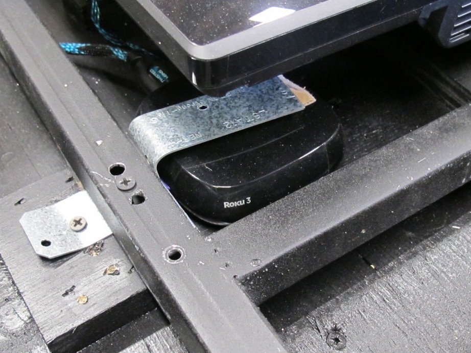
A swivel bracket has also been added so that the TV can be rotated to other parts of the dock. The docking station has a wired Ethernet connection, and wireless power is supplied to the TV.
From the rafters, a rubber pad was added to protect against moisture.
Step 6: What could be changed
After graduation homemade thoughts always arise that everything could be done differently. The author of this homemade product did not bypass such thoughts.
The changes that he would have necessarily made if he had built everything from the very beginning:
• Place the linear actuator and pivot arm in one direction. Placing it in the middle means making the box taller (to make room for the TV). Moving it to the side would reduce the overall height of the hull.
• Instead of bearings, I would use bronze bushings (or, even better, plastic sleeves). This will reduce the width of the case and be strong enough.
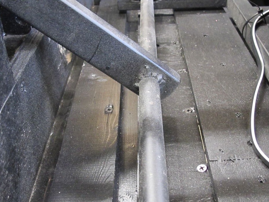
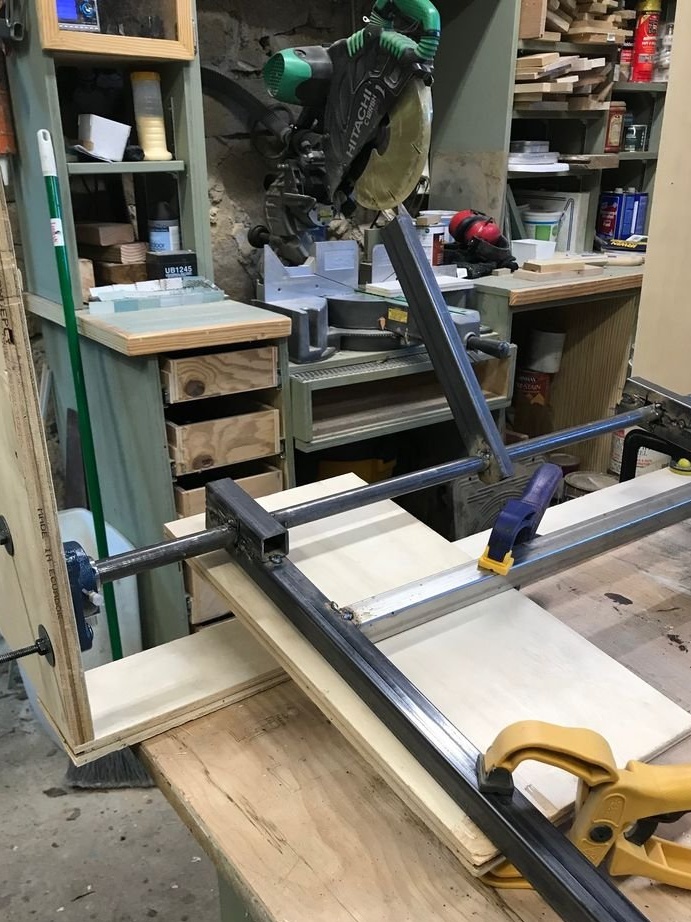
• I would buy a decent metal cutting saw so that I could put the frame brackets on the hinge shaft and weld it in place. Welding the frame to the bottom of the shaft created a gap, the elimination of which was difficult to solve.