


I think there are people who are somewhat inconvenient to constantly approach the lamp and turn on the light, which is why there is a desire to make the entire lamp turn on independently. Yes, there are “smart” sockets that are controlled via Wi-Fi, there are simpler ones on which you can set the response time, but, of course, you can always buy a dimmer and not really worry. But all this can be done. do it yourself (except for Wi-Fi-outlets), although this option is for, for example, LED strips, since there will be some nuances when managing the break, in the person of the aforementioned dimmer. In our case, the brightness depending on the surrounding lighting will smoothly change.
Necessary Details
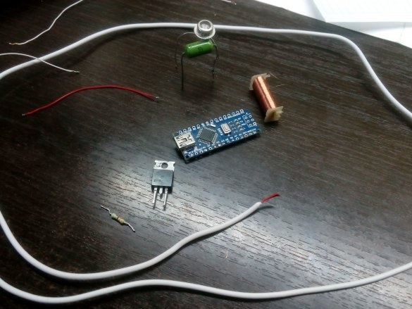
1., in this case - Nano, you can do something smaller, for example Micro
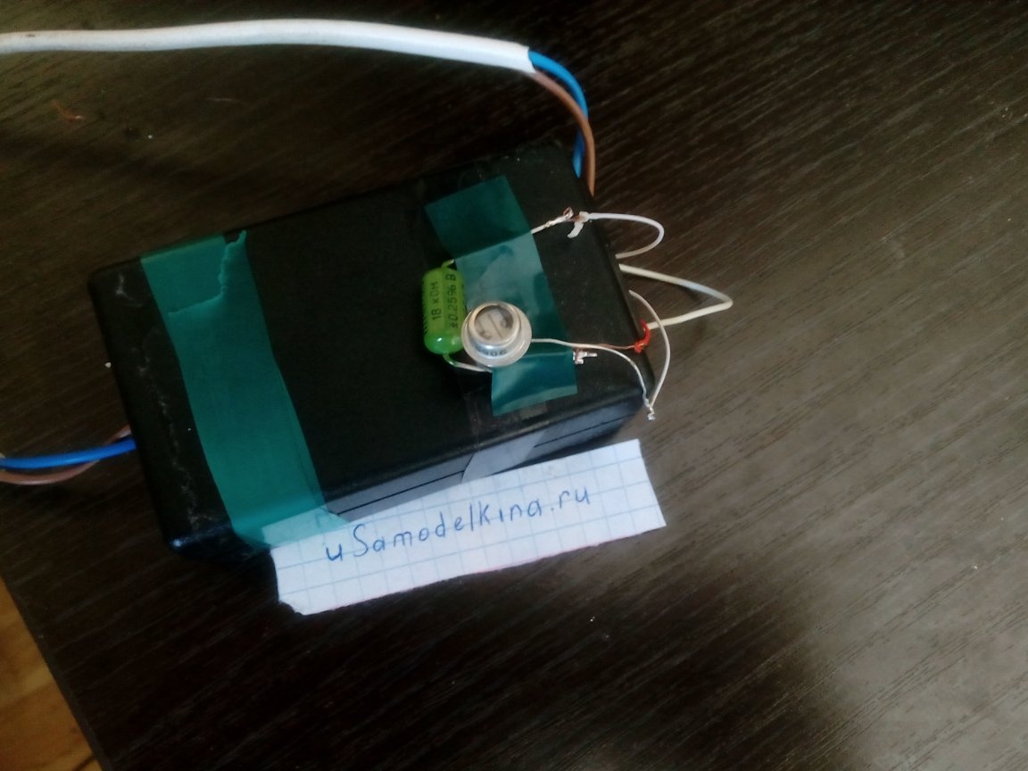
2. A photosensitive element, here is a resistor (18 KOhm) and a photoresistor (I have an SF-2 6A) connected in series. All this will work almost like a tuning resistor.
3. MOSFET transistor, better weaker, 55 amperes is too much (if the current consumption is small, then a particularly powerful transistor is not required)
4. Of course, wires. A thin wire is needed to lead the "sensor" closer to the window, the one that is thicker is connected to the lamp power supply and to Arduinka (and the module itself does not need to be hung on a thick wire, it consumes little anyway)

Assembly. Step 1
The work of this kind of light sensor should be checked in a good way, because I tried to do everything as cheaply and easier as I could.
To make it, you need a resistor and a photoresistor. We connect them in series, 5V and GND pins will be connected to the beginning and end, the central one will be connected to the given analogue contact in the firmware, its number will change.
If there is any doubt that such a sensor does not work very well, you can check it using the code below and the port monitor.
Code to check if in doubt:
#define potent_pin 0 // Middle foot contact, 0 changes to any other analog
int val;

void setup () {
  Serial.begin (9600); // Enable output to port at 9600 baud

}

void loop () {
  val = analogRead (potent_pin);
  val = map (val, 0, 1023, 0, 100); // 100 can be replaced with any value up to 1023 inclusive
  val = constrain (val, 0, 100); // 100 change to the value specified above, if it was changed
   Serial.println (val); // output to port monitor
  delay (30); //delay

}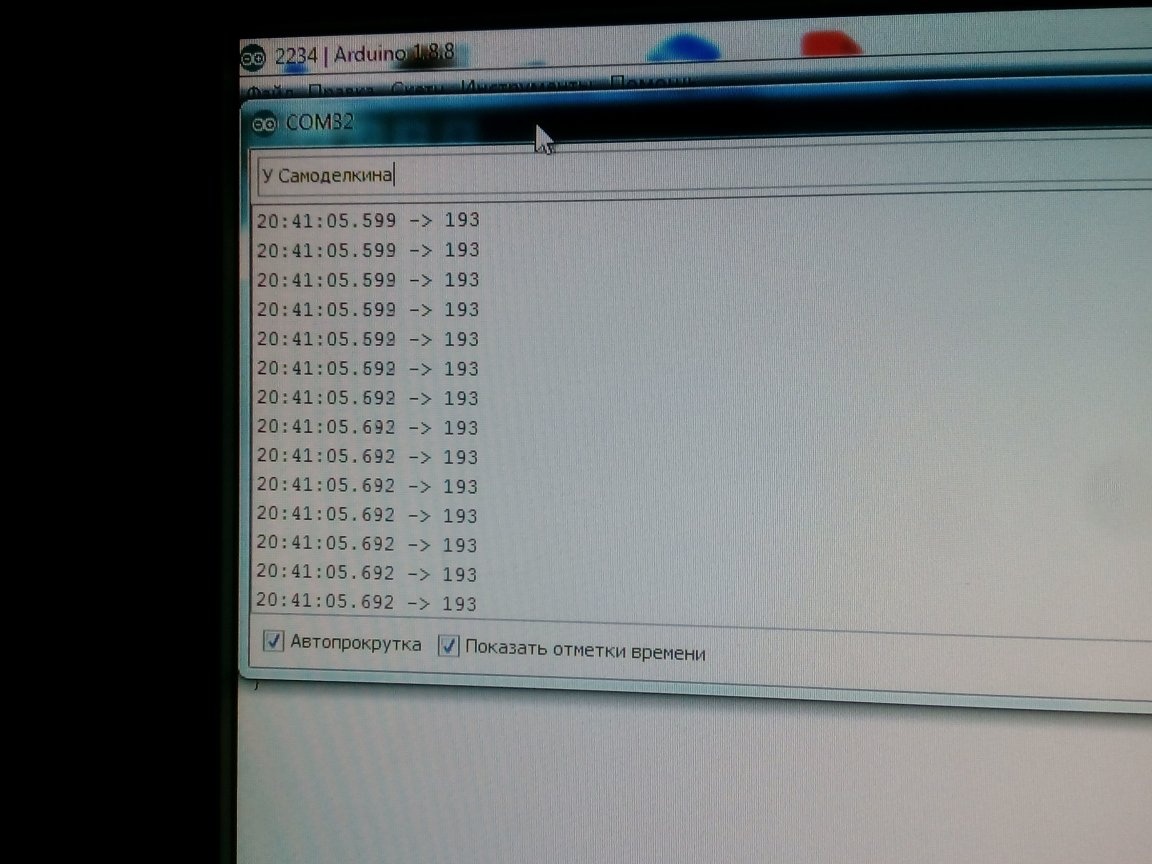

If the output values change, depending on the illumination, then everything is fine
Assembly. Step 2
Great, the sensor is working. Now is the time to create a code for generating a PWM signal for controlling a fieldwork.
ATTENTION. PWM on ATmega168 / ATmega328 controllers is generated only at 3, 5, 6, 9, 10, and 11 digital pins.
Code 2:
int pwm;

void setup () {

}

void loop () {
pwm = analogRead (0);
pwm = map (pwm, 1023, 0, 0, 255);
pwm = constrain (pwm, 0, 255);
analogWrite (3, pwm-255); // PWM to the third digital

}
The number 255 can be changed in the range from 0 to 1023 inclusive, and this value can be changed directly "on the go." As practice has shown me, a maximum of 255 is the best option, if less - it burns too bright during the day, if more - burns weaker then when necessary.
Assembly. The final
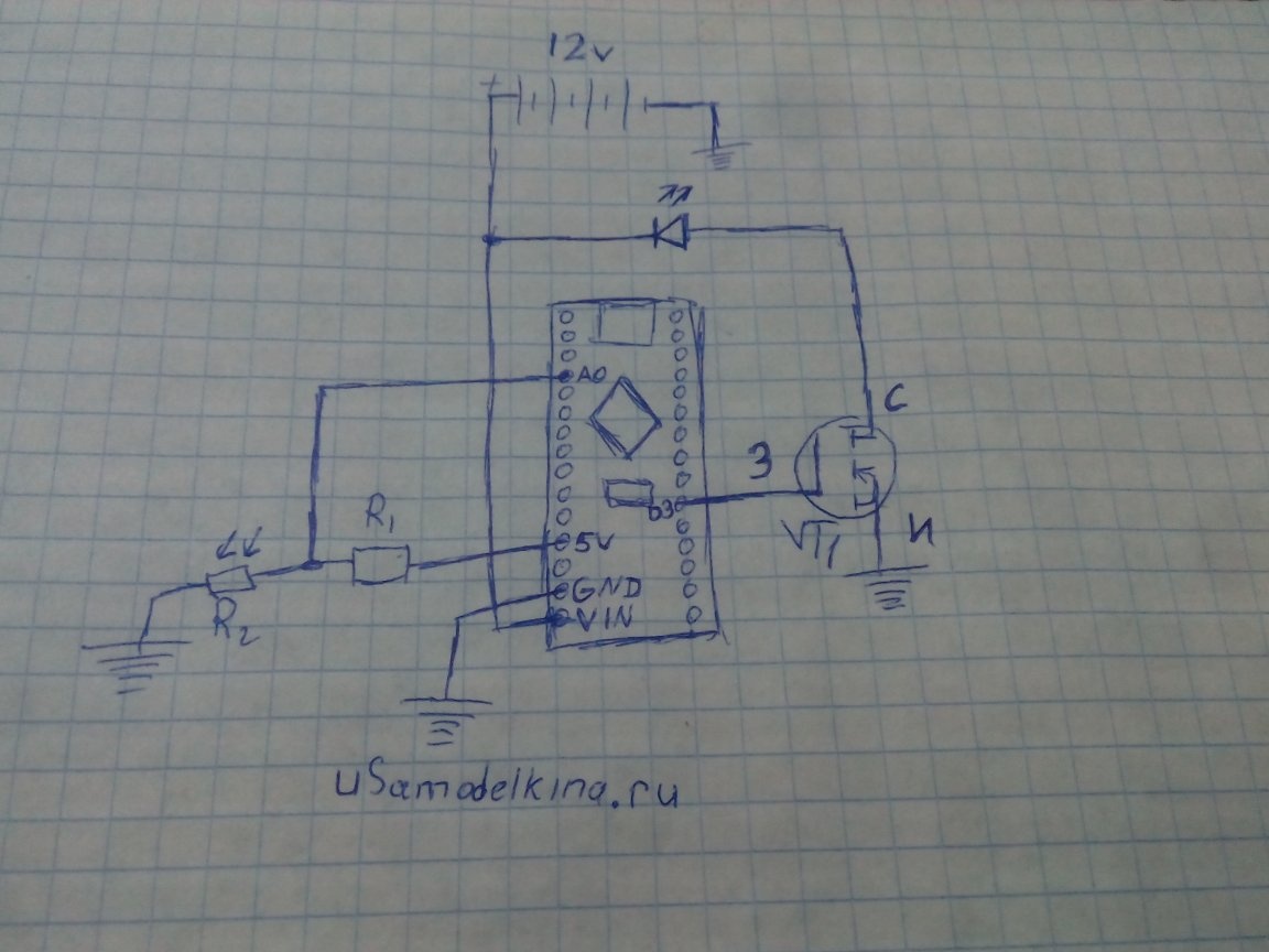
At the 5V and GND pin, we solder the extreme contacts of our resistor, at A0 we put the middle one. We solder the gate of the field-effect transistor to D3, the source to the minus power from the Arduino and the power supply, the LEDs to the minus to the drain and the plus of the power to the plus of the source. Schematically, it looks something like this:
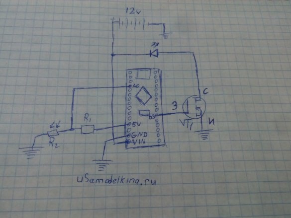
It is not necessary to put a field effect transistor on a radiator, unless, of course, a powerful one is used, but there is no sense in a particularly powerful one. But a long wire was needed to lead the sensor to a place where external light does not fall, for example, behind a flower or outside through a window, etc. It is advisable to put a capacitor on the power supply and the drain of the field-effect transistor, for example, my tape began to work not really right. Arduino can be powered not from USB or the power supply from the phone, but from the tape power supply, by supplying a voltage of 7-15 volts to GND and VIN.
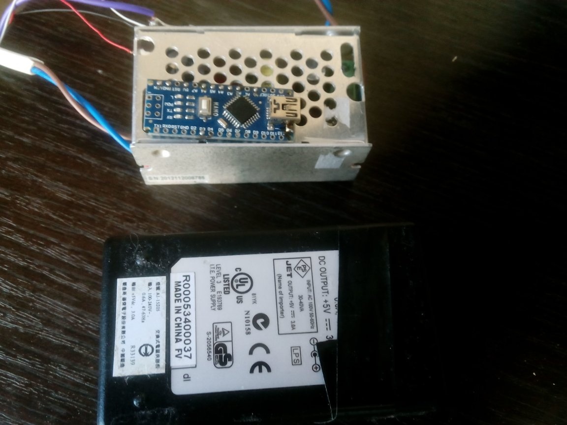
The case is made of the case of a dead power supply, where I put the power supply of the tape and Arduino, with a soldered connector. He almost fit in size, but he was already constantly on tape.


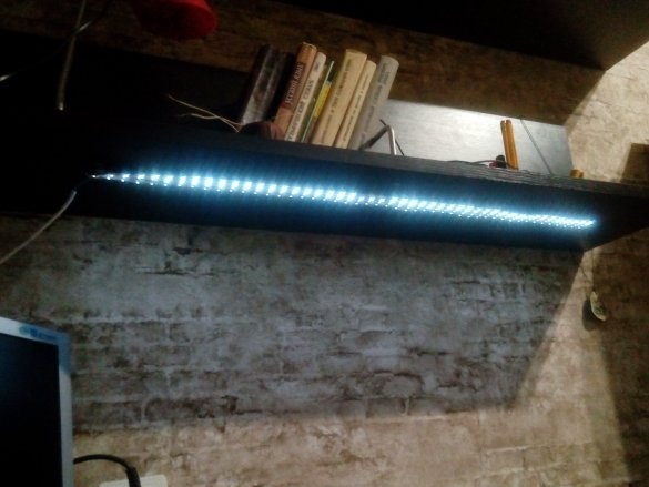
So I closed the sensor with my hand:

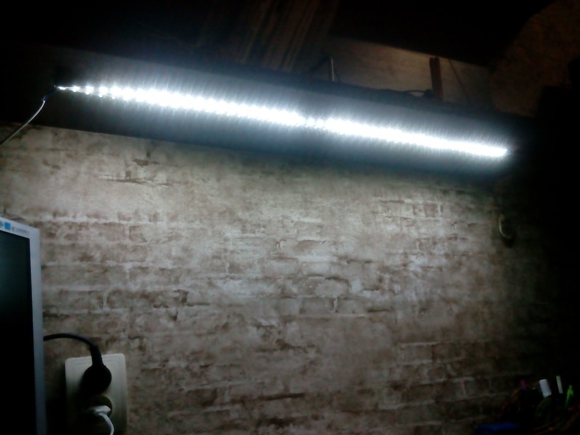
But I do not hold my hand over him:
Where can this come in handy?
This design can help with any delicate work where you need a stable backlight, for example, if you forgot to turn on the light, but the tape is turned on. It is also convenient to use it if you have seedlings somewhere for further planting on the garden bed. Where is it to use, to judge, of course, to you.
P.S. True, my hands are crooked and I stuck the LED incorrectly on the circuit.