

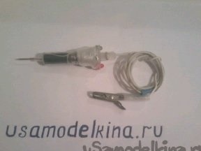
When troubleshooting a car wiring, you often have to use measuring and testing instruments. I bring to your attention a simple probe. Here is his diagram
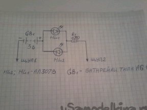
This probe is a combination of the simplest indicators of voltage and resistance. The use of this device provides certain advantages over others. Since the probe is always ready for use, the batteries are charged during operation. The probe does not contain switches, which is convenient when using it. With this probe, you can check for voltage from 6 -7 V, while the green LED HL2 is lit, check the health of diodes, transistors, capacitors, distributors, switches, and the red LED HL1 is lit. In the "dialing" mode, when the probes are closed, the HL1 LED lights up. When connecting to the probe 1 minus, and to the probe 2, respectively, plus the power source, the HL2 LED lights up. Resistor R1 is restrictive, its resistance is selected for operation with voltages up to 28 V. To assemble the probe, we need the following materials and tools:
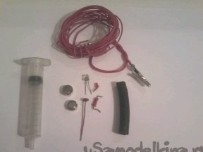
1 - any LEDs, for example AL307v, one red, the other green, MLT resistor - 0.5W 470 ohm; 5 - vat syringe; AG 13 batteries - 2 pcs., they are just placed in the syringe body; mounting wires; crocodile clip - 1 pc. 2 - soldering iron; solder; tweezers; a piece of soft rubber hose that fits easily into the syringe body; nippers; pliers; a small piece of dense rubber; 5 -10 cm of copper wire with a cross section of 1 mm. We assemble as follows:
Step 1 .
From a copper wire we make a probe. On the one hand we grind it with a file so that it is sharp, and on the other hand we service it with solder so that it fits tightly into the lower opening of the syringe. Next, solder the resistor R1 to the upper end of the probe, put a hose on the resistor and the probe so that the resistor is completely hidden inside the hose.
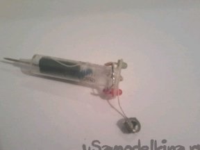
Step 2. Solder a thin wire to the second end of the resistor and bring it out. In the upper part of the syringe we make two holes for the LEDs, and install the LEDs there.
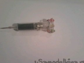
All this is shown in the photo.On the top of the hose we put a circle cut out of thick paper. We put a round terminal on it with a thin wire soldered to it - this will be a positive output of the batteries.
Step 3. We place two batteries - a plus down, on them we establish a circle of dense rubber
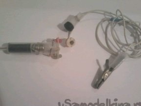
with a hole in the middle, which includes the wire of the 1st probe. At the end of this probe, solder the crocodile clip - this will be the negative probe. We solder the whole scheme to the end.
Step 4
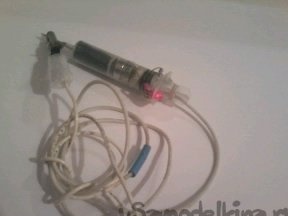
We insert the piston of the syringe into the syringe and cut off the excess part. We insulate the LEDs on top with insulating material. Due to the elasticity of the hose, a spring for compressing the batteries is not needed. That's it, the probe is ready. A positive probe will be probe 2. If necessary, they can pierce the insulation of the tested wires. With a strong discharge of the device’s batteries, it is enough to connect the probes to the machine’s battery for 10-15 minutes, and the device is ready for use again. With a minimum of parts, a good multifunctionality of the device is achieved. This probe is very suitable for me, I will carry it in the car, and it takes up little space.